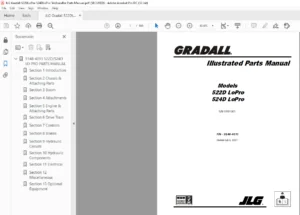
JLG Gradall 522D 524D Telehandler Parts Manual – PDF DOWNLOAD
Original price was: $53.95.$21.95Current price is: $21.95.
JLG Gradall 522D 524D Telehandler Parts Manual – PDF DOWNLOAD
S/N 0277001
P/N – 9138-4001
Description
JLG Gradall 522D 524D Telehandler Parts Manual – PDF DOWNLOAD
FILE DETAILS:
JLG Gradall 522D 524D Telehandler Parts Manual – PDF DOWNLOAD
Format: PDF
Language: English
Brand: JLG
DESCRIPTION:
JLG Gradall 522D 524D Telehandler Parts Manual – PDF DOWNLOAD
S/N 0277001
P/N – 9138-4001
IMAGES PREVIEW OF THE MANUAL:
TABLE OF CONTENTS:
JLG Gradall 522D 524D Telehandler Parts Manual – PDF DOWNLOAD
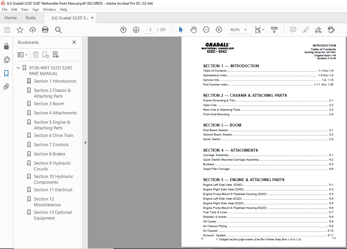
SECTION 1 — INTRODUCTION
Table of Contents 1-1 thru 1-4
Alphabetical Index 1-5 thru 1-8
Service Kits 1-9, 1-10
Part Number Index 1-11 thru 1-26
SECTION 2 — CHASSIS & ATTACHING PARTS
Frame Shrouding & Trim 2-1
Open Cab 2-2
Rear Axle & Attaching Parts 2-3
Front Axle Mounting 2-4
SECTION 3 — BOOM
First Boom Section 3-1
Second Boom Section 3-2
Quick Switch 3-3
SECTION 4 — ATTACHMENTS
Carriage Assembly 4-1
Quick Switch Mounted Carriage Assembly 4-2
Buckets 4-3
Slope Piler Carriage 4-4
SECTION 5 — ENGINE & ATTACHING PARTS
Engine Left Side View (524D) 5-1
Engine Right Side View (524D) 5-2
Engine Pump Mount & Flywheel Housing (524D) 5-3
Engine Left Side View (522D) 5-4
Engine Right Side View (522D) 5-5
Engine Pump Mount & Flywheel Housing (522D) 5-6
Fuel Tank & Lines 5-7
Radiator & Hoses 5-8
Oil Cooler 5-8
Air Cleaner Piping 5-9
Air Cleaner 5-10
Exhaust System 5-11
* Changed the final page number of the Part Number Index from 1-19 to 1-26
KG 1-2
SECTION 6 — DRIVE TRAIN
Front Axle Assembly 6-1
Front Axle Housing 6-2
Front Axle Differential Carrier 6-3
Brake Assembly 6-4
Front Axle Shaft & Planetary Wheel End 6-5
Rear Steering Axle Drive Hub 6-6
Rear Steering Axle Non-Drive Hub 6-7
Wheels & Tires 6-8
SECTION 7 — CONTROLS
Tilt & Sway 7-1
Accelerator Pedal Assembly 7-2
Steering Column – Forward Nuetral Reverse Shifter 7-3
Floorplate Components 7-4
Brake & Inching Linkage 7-5
SECTION 8 — BRAKES
Service Brake Lines 8-1
SECTION 9 — HYDRAULIC CIRCUITS
Oil Supply & Pressure Lines 9-1
Dump Circuit 9-2
Drive Circuit (front) 9-3
Drive Circuit (rear) 9-4
Lift Cylinder 9-5
Crowd Cylinder 9-6
Tilt & Tilt Compensating Cylinder 9-7
Sway Cylinder 9-8
Steering Cylinder 9-9
Joystick Circuit 9-10
SECTION 10 — HYDRAULIC COMPONENTS
Lift Cylinder (Iowa) 10-1
INTRODUCTION
Table of Contents
Starting Serial No 0277001
Original Issue 1-98
1-3
SECTION 10 — HYDRAULIC COMPONENTS (continued)
Crowd Cylinder 10-2
Tilt Cylinder (Iowa) 10-3
Compensating Cylinder (Iowa) 10-4
Sway Cylinder (Iowa) 10-5
Steering Cylinder (Iowa) 10-6
Main Hydraulic Control Valve 10-7
Rear Drive Motor 10-8
Priority Flow Control Valve 10-9
Flow Divider Valve 10-10
Brake Valve 10-11
Solenoid Valve 10-12
Sway Cylinder Valve 10-13
Inching Valve 10-14
Main Hydraulic Pump 10-15
Hydrostatic Transmission Pump 10-16
Front Drive Motor (524D) 10-17
Hydraulic Reservoir & Filters 10-18
Joystick Assembly 10-19
Traction Lock Valve 10-20
Quick Start Cylinder & Valve Assembly 10-21
Front Drive Motor (522D) 10-22
SECTION 11 — ELECTRICAL
Dash Panel 11-1
Engine Wiring Harness 11-2
Dash Harness Assembly 11-3
Gauge Panel 11-4
Battery & Cables 11-5
SECTION 12 — MISCELLANEOUS
Frame Decals 12-1
Boom Decals 12-2
SECTION 13 — OPTIONAL EQUIPMENT
Inline Bypass 13-1
INTRODUCTION
Table of Contents
Starting Serial No 0277001
Original Issue 1-98
Revised 8-16-99
JJ * Renamed page 11-2 from Engine Wiring to Engine Wiring Harness
*
JH 1-4
SECTION 13 — OPTIONAL EQUIPMENT (continued)
L H Tilt Assembly 13-2
L H Sway Assembly 13-3
L H Tilt/Sway Field Kit 13-4
Overhead Window 13-5
Engine Block Heater 13-6
Hydraulic Reservoir Heater Installation 13-7
Auxiliary Hydraulics Field Kit (2-section boom) 13-8
Auxiliary Hydraulics & L H Sway Assembly (2-section boom) 13-9
Control Valve Assembly 13-10
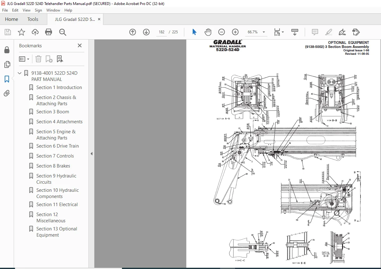
Three Section Boom Assembly 13-11
Auxiliary Field Kit (3-section boom) 13-12
Dual P O Check Valve 13-13
Slope Piler Carriage Sway Cylinder 13-14
Cab Enclosure Installation (9134-5003) 13-15
Cab Enclosure Installation (9134-5003) – Cont 13-16
Cab Enclosure Kit (9114-3267) – Upper Window & Front Wiper Assembly 13-17
Cab Enclosure Kit (9114-3267) – L H Side Assembly 13-18
Cab Enclosure Kit (9114-3267) – Cab Glass 13-19
Auxiliary Hydraulics & L H Sway (9108-5127) 13-20
Auxiliarty Hydraulics W/Electrics (3-section boom) (9108-5128) 13-21
Auxiliary Hydraulics W/Electrics (2-section boom) (9108-5125) 13-22
Work Light Package (9138-5004) 13-23
Foam Tires (2-section boom) (9138-5005) 13-24
Foam Tires (3-section boom) (9138-5006) 13-25
Ether Start Field Kit 13-26
Rear Axle Rework Kit 13-27
Rear Axle Advantage Kit 13-28
Low Profile Machine Package 522D (9139-5004) 13-29
Low Profile Machine Package 524D (9138-5010) 13-30
Low Profile Sway Cylinder (9138-3015) 13-31
INTRODUCTION
Table of Contents
Starting Serial No 0277001
Original Issue 1-98
Revised 6-1-99
* Added pages 13-29, 13-30 & 13-31
*
*
*
ACCELERATOR CABLE 5-1
ACCELERATOR PEDAL 7-2
AIR CLEANER 5-10
AIR CLEANER ELEMENT 5-10
AIR CLEANER SERVICE INDICATOR 5-9
ALTERNATOR 5-2
ALTERNATOR FAN 5-2
ATTACHMENTS 4-1 thru 4-4
AUXILIARY HYDRAULICS (2s boom) 13-8
AUXILIARY HYDRAULICS (3s boom) 13-12
AUXILIARY HYDRAULICS & L H Sway (2s boom) 13-9
BATTERY 11-5
BATTERY HOLD DOWN 11-5
BATTERY CABLES 11-5
BEARING PADS (Boom Sections) 3-1, 3-2
BLOCK HEATER 13-6
BOOM DECALS 12-2
BOOM SECTIONS 3-1, 3-2
BOOM 3 SECTIONS 13-11
BRAKE PEDAL 7-5
BRAKE VALVE 10-11
BRAKE WARNING LIGHT 11-4
BREATHER (Filler cap) 10-18
BUCKETS 4-3
CAB ENCLOSURE INSTALLATION 13-15, 13-16
CAB ENCLOSURE KIT 13-17, 13-18, 13-19
CARRIAGE & FORKS 4-1
COMPENSATING CYLINDER 10-4
COMPENSATING CYLINDER HYDRAULIC CIRCUIT 9-7
CONTROL VALVES 10-7, 10-9, 10-10
CROWD CYLINDER 10-2
CROWD CYLINDER HYDRAULIC CIRCUIT 9-6
DASH HARNESS 11-3
DECALS 12-1, 12-2
DECK 2-1
DRIVE CIRCUIT (Front) 9-3
DRIVE CIRCUIT (Rear) 9-4
INTRODUCTION
Alphabetical Index
Starting Serial No 0277001
Original Issue 1-98
Revised 5-5-98
KG 1-5
* All cab enclosure pages re-formatted and combined to alleviate confusion One cab enclosure
kit will work for all “D” series models Multiple page number changes in section 13
DUAL P O CHECK VALVE 13-3
DUMP CIRCUIT 9-2
ELECTRICAL SYSTEMS 11-1 thru 11-5
ENGINE LEFT SIDE VIEW (524D) 5-1
ENGINE LEFT SIDE VIEW (522D) 5-4
ENGINE MOUNT 5-1, 5-4
ENGINE RIGHT SIDE VIEW (524D) 5-2
ENGINE RIGHT SIDE VIEW (522D) 5-5
ENGINE THROTTLE CONTROL 5-1, 5-4
EXHAUST PIPE 5-11
EXHAUST STACK 5-11
EXHAUST SYSTEM 5-11
FILTERS 10-18
FILTER ELEMENT 10-18
FIRST BOOM SECTION 3-1
FIRST BOOM SECTION MOUNTING PIN 3-1
FLOORPLATE COMPONENTS 7-4
F-N-R SHIFTER 7-3
FRAME 2-1
FRAME SHROUDING & TRIM 2-1
FRONT AXLE 6-1
FRONT AXLE MOUNTING 2-4
FRONT AXLE DIFFERENTIAL CARRIER 6-3
FRONT AXLE DRIVE MOTOR 10-17
FRONT AXLE HOUSING 6-2
FRONT AXLE SHAFT & PLANETARY WHEEL END 6-5
FRONT BRAKE ASSEMBLY 6-4
FRONT DISC WHEEL & RIM 6-7
FUEL GAUGE 11-2
FUEL LEVEL SENDER 5-7
FUEL LINES 5-7
FUEL TANK & CAP 5-7
HOOD 2-1
HORN 2-1
HORN BUTTON 11-3
KG 1-6
INTRODUCTION
Alphabetical Index
Starting Serial No 0277001
Original Issue 1-98
HORN WIRING 11-3
HOURMETER 11-4
HYDRAULIC CIRCUITS 9-1 THRU 9-10
IGNITION SWITCH 11-3
INCHING VALVE 7-4, 7-5, 10-14
INSTRUMENT PANEL 11-1, 11-4
JOYSTICK 9-10, 10-19
KITS 1-10, 1-11
LEFT HAND TILT/SWAY CONTROL 13-4
LIFT CYLINDER 10-1
LIFT CYLINDER HYDRAULIC CIRCUIT 9-5
MAIN BOOM SECTIONS 3-1, 3-2
MAIN HYDRAULIC PUMP 5-1, 5-4, 10-15
MISCELLANEOUS ELECTRICAL COMPONENTS 11-1 thru 11-5
MUFFLER 5-11
NEGATIVE BATTERY CABLE 11-5
OIL COOLER 5-8, 9-2
OIL FILTER 5-1, 5-4, 10-18
OIL PRESSURE GAUGE 11-4
OIL PRESSURE SENDER 5-1, 5-4
OIL RESERVOIR 10-18
OIL SUPPLY & PRESSURE LINES 9-1
POSITIVE BATTERY CABLE 11-5
PRIORITY FLOW CONTROL VALVE 10-9
QUICK SWITCH ASSEMBLY 3-3
QUICK SWITCH MOUNTED CARRIAGE ASSEMBLY 4-2
RADIATOR & HOSES 5-8
REAR AXLE FRAME 2-3
REAR AXLE MOUNTING PIN 2-3
REAR DRIVE MOTOR 10-8
KG 1-7
INTRODUCTION
Alphabetical Index
Starting Serial No 0277001
Original Issue 1-98
REAR STEERING AXLE 2-3
REAR STEERING AXLE DRIVE HUB 6-6
Rear Steering Axle Non-Drive Hub 6-7
REPAIR KITS 1-10, 1-11
RESERVOIR FILLER-BREATHER 10-18
RESERVOIR SUPPLY CIRCUIT 9-1
RESERVOIR 10-18
RESERVOIR FILTER 10-18
SEAT 2-1
SEAT BELT 2-1
SECOND BOOM SECTION 3-2
SERVICE BRAKE LINES 8-1
SERVICE KITS 1-9, 1-10
SOLENOID VALVE 10-12
STARTER MOTOR 5-2, 5-5
STEERING COLUMN 7-3
STEERING CYLINDER 10-6
STEERING CYLINDER HYDRAULIC CIRCUIT 9-9
STEERING KNUCKLES 2-3
STEERING ORBITROL 7-3
STEERING WHEEL 7-3
SUPPLY HYDRAULIC CIRCUIT 9-1
SWAY CONTROL HANDLE & LINKAGE 7-1
SWAY CYLINDER 10-5
SWAY CYLINDER HYDRAULIC CIRCUIT 9-8
THERMAL BYPASS 13-1
THREE SECTION BOOM 13-11
THREE SECTION BOOM AUXILIARY HYDRAULICS 13-12
TIE ROD ARM 2-3
TILT CONTROL HANDLE & LINKAGE 7-1
TILT CYLINDER 10-3,
TILT CYLINDER HYDRAULIC CIRCUIT 9-7
TRACTION LOCK VALVE 10-20
TRAVEL ALARM 2-1
WATER TEMPERATURE GAUGE 11-4
WATER TEMPERATURE SENDER 5-2, 5-5
WHEELS & TIRES 6-8
WIRING HARNESS 5-1, 5-4, 11-2, 11-3
JLG GRADALL 522D 524D TELEHANDLER PARTS MANUAL – PDF DOWNLOAD:
PLEASE NOTE:
- This is the same manual used by the dealers to diagnose and troubleshoot your vehicle
- You will be directed to the download page as soon as the purchase is completed. The whole payment and downloading process will take anywhere between 2-5 minutes
- Need any other service / repair / parts manual, please feel free to contact [email protected] . We still have 50,000 manuals unlisted