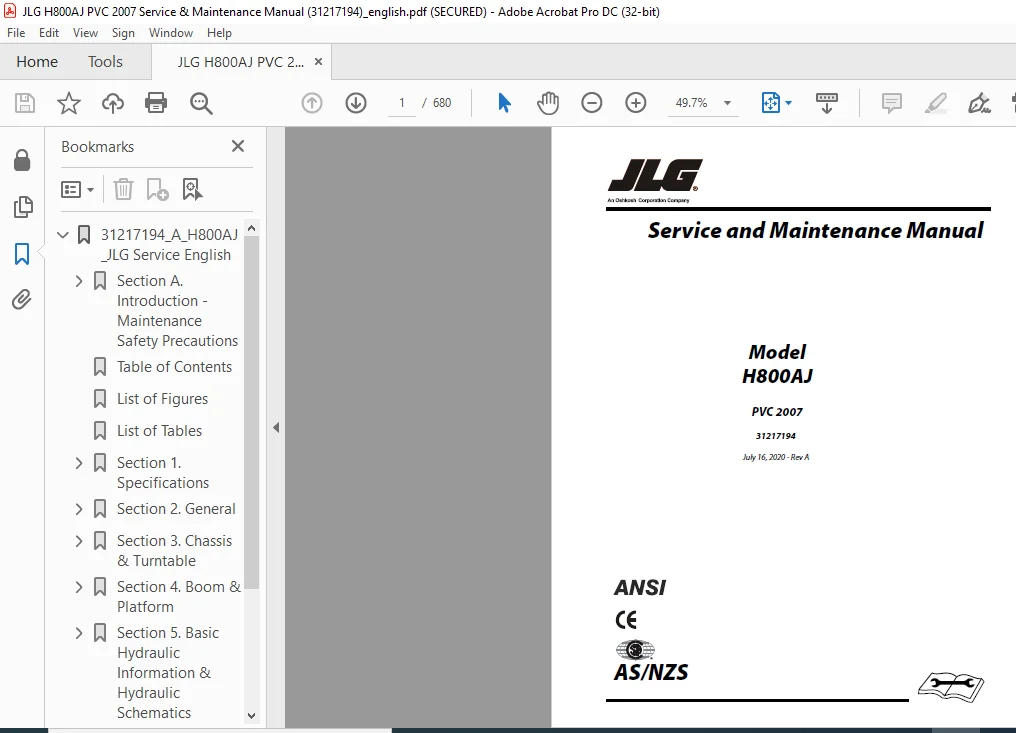
JLG H800AJ PVC 2007 Service & Maintenance Manual (31217194) – PDF DOWNLOAD
TABLE OF CONTENTS:
JLG H800AJ PVC 2007 Service & Maintenance Manual (31217194) – PDF DOWNLOAD
31217194_A_H800AJ_JLG Service English..............................................................  1
	Section A. Introduction - Maintenance Safety Precautions.......................................  3
		A General..................................................................................  3
		B Hydraulic System Safety..................................................................  3
		C Maintenance..............................................................................  4
	Table of Contents..............................................................................  7
	List of Figures................................................................................ 15
	List of Tables................................................................................. 22
	Section 1. Specifications...................................................................... 25
		1.1 Operating Specifications............................................................... 25
		1.2 Tires.................................................................................. 25
		1.3 Capacities............................................................................. 25
		1.4 Engine Data............................................................................ 25
		1.5 Hydraulic Oil.......................................................................... 26
		1.6 Critical Stability Weights............................................................. 27
		1.7 Maintenance and Lubrication............................................................ 29
		1.8 ThreadLocking Compound................................................................. 32
		1.9 Torque Charts.......................................................................... 33
			SAE Fastener Torque Chart.............................................................. 33
			SAE Fastener Torque Chart (Continued).................................................. 34
			SAE Fastener Torque Chart (Continued).................................................. 35
			SAE Fastener Torque Chart (Continued).................................................. 36
			SAE Fastener Torque Chart (Continued).................................................. 37
			SAE Fastener Torque Chart (Continued).................................................. 38
			Metric Fastener Torque Chart........................................................... 39
			Metric Fastener Torque Chart (Continued)............................................... 40
			Metric Fastener Torque Chart (Continued)............................................... 41
			Metric Fastener Torque Chart (Continued)............................................... 42
	Section 2. General............................................................................. 43
		2.1 Machine Preparation, Inspection, and Maintenance....................................... 43
			General................................................................................ 43
			Preparation, Inspection, and Maintenance............................................... 43
			Pre-Start Inspection................................................................... 43
			Pre-Delivery Inspection and Frequent Inspection........................................ 43
			Annual Machine Inspection.............................................................. 43
			Preventive Maintenance................................................................. 43
		2.2 Service and Guidelines................................................................. 44
			General................................................................................ 44
			Safety and Workmanship................................................................. 44
			Cleanliness............................................................................ 44
			Components Removal and Installation.................................................... 44
			Component Disassembly and Reassembly................................................... 45
			Pressure-Fit Parts..................................................................... 45
			Bearings............................................................................... 45
			Gaskets................................................................................ 45
			Bolt Usage and Torque Application...................................................... 45
			Hydraulic Lines and Electrical Wiring.................................................. 45
			Hydraulic System....................................................................... 45
			Lubrication............................................................................ 46
			Battery................................................................................ 46
			Lubrication and Servicing.............................................................. 46
		2.3 Lubrication and Information............................................................ 46
			Hydraulic System....................................................................... 46
			Hydraulic Oil.......................................................................... 46
			Changing Hydraulic Oil................................................................. 46
			Lubrication Specifications............................................................. 46
		2.4 Cylinder Drift......................................................................... 47
			Theory................................................................................. 47
			Cylinder Leakage Test.................................................................. 47
			Cylinder Thermal Drift................................................................. 47
		2.5 Pins and Composite Bearing Repair Guidelines........................................... 48
		2.6 Welding on JLG Equipment............................................................... 48
			Do the Following When Welding on JLG Equipment......................................... 48
			DO NOT Do the Following When Welding on JLG Equipment.................................. 48
	Section 3. Chassis & Turntable................................................................. 55
		3.1 Tires & Wheels......................................................................... 55
			Tire Damage............................................................................ 55
			Tire Replacement....................................................................... 55
			Wheel Replacement...................................................................... 55
			Wheel Installation..................................................................... 55
		3.2 Powertrain Operating Modes............................................................. 56
			Hybrid Mode............................................................................ 56
			Electric Mode.......................................................................... 56
			Switching Between Modes on the Fly..................................................... 56
			Idle Reduction Stop Start.............................................................. 57
		3.3 Drive Orientation System............................................................... 58
		3.4 Oscillating Axle System................................................................ 58
		3.5 Lockout Cylinder Bleeding.............................................................. 59
		3.6 Oscillating Axle Lockout Test.......................................................... 62
		3.7 Drive System........................................................................... 64
		3.8 Drive Hub (Torque)..................................................................... 65
			Removal................................................................................ 65
			Installation........................................................................... 65
		3.9 Drive Hub.............................................................................. 66
			Assembly/Disassembly................................................................... 66
		3.10 Drive brake........................................................................... 66
		3.11 Drive Motor........................................................................... 66
			Removal................................................................................ 66
			Installation........................................................................... 66
			Description............................................................................ 67
			Shaft Seal Replacement................................................................. 67
			Loop Flushing Valve.................................................................... 68
			Troubleshooting........................................................................ 69
			Disassembly............................................................................ 70
			Inspection............................................................................. 74
			Assembly............................................................................... 76
			Initial Start-up Procedures............................................................ 81
		3.12 Swing Drive........................................................................... 84
			Roll, Leak And Brake Testing........................................................... 84
			Tightening and Torquing Bolts.......................................................... 85
			Motor Control Valve Disassembly........................................................ 86
			Motor and Brake Disassembly............................................................ 87
			Main Drive Disassembly................................................................. 88
			Hub-Shaft Disassembly.................................................................. 89
			Carrier Disassembly.................................................................... 90
			Hub-Shaft Assembly..................................................................... 91
			Carrier Assembly....................................................................... 91
			Main Drive Assembly.................................................................... 92
			Motor and Brake Assembly............................................................... 93
			Motor Control Valve Assembly........................................................... 94
		3.13 Swing Motor...........................................................................101
			Disassembly and inspection.............................................................101
			Assembly...............................................................................108
			One Piece Stator Construction..........................................................116
		3.14 Swing Hub Installation................................................................117
			Procedure For Setting Swing Gear Backlash..............................................117
			Swing Drive Lubrication................................................................118
		3.15 Swing Hub Removal.....................................................................118
		3.16 Swing Bearing.........................................................................119
			Turntable Bearing Mounting Bolt Condition Check........................................119
			Wear Tolerance.........................................................................122
			Swing Bearing Replacement..............................................................122
			Swing Bearing Torque Values............................................................123
		3.17 Chassis Tilt Indicator System.........................................................125
		3.18 Rotary Coupling.......................................................................126
		3.19 Generator.............................................................................132
			Maintenance Schedule...................................................................132
			Overload Protection....................................................................133
			Inspecting Brushes, Replacing Brushes, and Cleaning Slip Rings.........................133
			Troubleshooting........................................................................135
			Generator Disassembly and Assembly.....................................................136
			Lead Connection List for Generator.....................................................144
		3.20 Cold Start System.....................................................................150
			Engine Warmup..........................................................................150
		3.21 Clutch Adapter Plate Installation.....................................................150
		3.22 Clutch Kit & Release Shaft Installation...............................................151
			Clutch Kit.............................................................................151
			Release Shaft..........................................................................152
		3.23 Clutch Installation...................................................................153
		3.24 Clutch Linear Actuator/Throwout Bearing Positioning installation Procedure............153
		3.25 Counterweight.........................................................................156
	Section 4. Boom & Platform.....................................................................157
		4.1 Boom Systems...........................................................................157
			Switch Systems.........................................................................157
			Above Elevation (Above Horizontal) Cutout System.......................................157
			Beyond Transport Position - Drive Speed Cutback System.................................157
			Drive/Steer – Boom Function Interlock System (CE Only).................................157
			Transport Position Interlock System (CE only)..........................................157
			Platform Control Enable System.........................................................157
			Function Speed Control System..........................................................157
			Platform...............................................................................158
			Main Lift End Stroke Dampening System..................................................158
			QuikStick Lift System..................................................................158
			Tower Boom Sequence Valve System.......................................................158
			Upright Level Override System..........................................................158
			Ground Control Keyswitch System........................................................158
		4.2 Main Boom Assembly.....................................................................162
			Removal................................................................................162
			Disassembly............................................................................163
			Inspection.............................................................................163
			Assembly...............................................................................163
			Installation...........................................................................164
		4.3 Upright................................................................................165
			Removal................................................................................165
			Installation...........................................................................166
		4.4 Tower Boom Assembly....................................................................168
			Removal................................................................................168
			Inspection.............................................................................168
			Assembly...............................................................................169
			Installation...........................................................................169
			Tower Out of Sync......................................................................170
		4.5 Upright Monitoring System (UMS)........................................................172
			Re-Synchronizing Upright...............................................................172
			Calibration............................................................................174
			Calibration Faults.....................................................................178
			Function Check.........................................................................178
			Service Mode/Tower Boom Retrieval......................................................180
		4.6 UMS Troubleshooting And Diagnostic Trouble Codes (DTC).................................184
			Backward Stability Concern DTC (2532)..................................................184
			Forward Stability Concern DTC (2530)...................................................184
			Out of Usable Range DTC (2531).........................................................184
			UMS Sensor Not Calibrated DTC (816)....................................................184
			UMS Sensor Faulted DTC (817)...........................................................184
			Calibration Faults.....................................................................184
		4.7 Platform...............................................................................185
			Platform Valve Removal.................................................................185
			Platform Valve Installation............................................................185
			Platform Support Removal...............................................................186
			Support Installation...................................................................187
		4.8 Bolt-on External Fall Arrest...........................................................189
			Inspection Before Use..................................................................189
			Installation...........................................................................189
		4.9 Articulating Jib.......................................................................191
			Removal................................................................................191
			Disassembly............................................................................191
			Inspection.............................................................................191
			Assembly...............................................................................192
			Installation...........................................................................192
		4.10 Rotator and Slave Cylinder............................................................193
			Removal................................................................................193
			Installation...........................................................................193
		4.11 Sequence For Hose Replacement In The Tower Boom.......................................194
		4.12 Limit Switches Adjustment.............................................................194
			Main Boom Horizontal Limit Switch......................................................194
			Tower Boom Horizontal Limit Switch.....................................................194
		4.13 Boom Valve Adjustment.................................................................198
			Tower Boom.............................................................................198
			Main Boom..............................................................................198
		4.14 Boom Cleanliness Guidelines...........................................................199
		4.15 Main Boom Powertrack..................................................................200
			Removal................................................................................200
			Installation...........................................................................200
		4.16 Powertrack Maintenance................................................................205
			Flat Bar Removal.......................................................................205
			Round Bar/Poly Bar Removal.............................................................205
			Removing and Installing Links..........................................................206
			Installing a New Flat Bar..............................................................209
			Installing a New Round Bar/Poly Roller.................................................210
			Replacing a Fixed End Bracket..........................................................210
			Replacing a Moving End Bracket.........................................................211
			Replacing a One Piece Bracket..........................................................211
		4.17 Rotator Assembly......................................................................213
			Theory of Operation....................................................................213
			Required Tools.........................................................................213
			Disassembly............................................................................216
			Inspection.............................................................................220
			Assembly...............................................................................220
			Installing Counterbalance Valve........................................................226
			Greasing Thrust Washers................................................................227
			Testing the Actuator...................................................................227
			Installation and Bleeding..............................................................228
		4.18 Foot Switch Adjustment................................................................228
			Troubleshooting........................................................................229
		4.19 Skyguard..............................................................................230
			Operation..............................................................................230
			Function Test..........................................................................230
			Diagnostics & Troubleshooting..........................................................231
	Section 5. Basic Hydraulic Information & Hydraulic Schematics..................................233
		5.1 Lubricating O-Rings in the Hydraulic System............................................233
			Cup and Brush..........................................................................233
			Dip Method.............................................................................234
			Spray Method...........................................................................234
			Brush-on Method........................................................................234
		5.2 Hydraulic Connection Assembly and Torque Specification.................................235
			Tapered Thread Types...................................................................235
			Straight Thread Types, Tube and Hose Connections.......................................235
			Straight Thread Types, Port Connections................................................236
			Flange Connection Types................................................................236
			Tightening Methods.....................................................................236
			Assembly And Torque Specifications.....................................................237
			Assembly Instructions for American Standard Pipe Thread Tapered (NPTF) Connections.....238
			Assembly Instructions for British Standard Pipe Thread Tapered (BSPT) Connections......239
			Assembly Instructions for 37° (JIC) Flare Fittings.....................................240
			Assembly Instructions for 45° SAE Flare Fittings.......................................244
			Assembly Instructions for O-Ring Face Seal (ORFS) Fittings.............................246
			Assembly Instructions for DIN 24° Flare Bite Type Fittings (MBTL and MBTS).............248
			Assembly Instructions for Bulkhead (BH) Fittings.......................................250
			Assembly Instructions for Metric ISO 6149 (MPP) Port Assembly Stud Ends................270
			Assembly instructions for Adjustable Port End (BSPP) Fittings..........................272
			Assembly Instructions for Flange Connections: (FL61 and FL62)..........................280
			Double Wrench Method...................................................................283
			FFWR and TFFT Methods..................................................................284
			Adjustable Stud End Assembly...........................................................284
			O-ring Installation (Replacement)......................................................285
		5.3 Hydraulic cylinders....................................................................286
			Axle Lockout Cylinder..................................................................286
			Slave Cylinder.........................................................................288
			Upright Level Cylinder.................................................................294
			Jib Lift Cylinder......................................................................295
			Main Boom Lift Cylinder................................................................301
			Tower Boom Lift Cylinder...............................................................302
			Master Cylinder........................................................................303
			Steer Cylinder.........................................................................309
			Cleaning and Inspection................................................................311
			Main Boom Telescope Cylinder...........................................................314
			Tower Boom Telescope Cylinder..........................................................320
		5.4 Cylinder Removal And Installation......................................................326
			Main Boom Telescope Cylinder Removal...................................................326
			Main Boom Telescope Cylinder Installation..............................................328
			Main Lift Cylinder Removal.............................................................329
			Main Lift Cylinder Installation........................................................330
			Upright Level Cylinder Removal.........................................................331
			Upright Level Cylinder Installation....................................................332
			Tower Boom Lift Cylinder Removal.......................................................332
			Tower Boom Lift Cylinder Installation..................................................333
			Tower Telescope Cylinder Removal.......................................................334
			Tower Telescope Cylinder Installation..................................................334
			Master Cylinder Removal................................................................335
			Master Cylinder Installation...........................................................335
		5.5 Pressure Setting Procedures............................................................336
			Set Up the Function Pump...............................................................336
			Adjustments Made at the Main Valve Block...............................................337
			Adjustments Made at the Platform Valve Block...........................................337
		5.6 Hydraulic Component Start-Up Procedures and Recommendations............................339
		5.7 Hydraulic drive pump pre-fill procedure................................................340
		5.8 Function Pump..........................................................................341
			Removal................................................................................341
			Installation...........................................................................341
			Initial Start-up Procedures............................................................343
			Troubleshooting........................................................................344
			Shaft Seal Replacement.................................................................348
			Control Assembly.......................................................................348
			Plug and Fitting Sizes and Torques.....................................................350
		5.9 Drive Pump.............................................................................351
			Removal................................................................................351
			Installation...........................................................................351
			Servo Controlled Piston Pump...........................................................352
			Charge Pump Adapter Assembly...........................................................355
			Manual Servo Control Basic Assembly....................................................356
			Manual Servo Control Assembly Options..................................................357
			Rotating Kit Assembly..................................................................359
			Fault- logic Trouble Shooting..........................................................360
			Start-up Procedure.....................................................................365
	Section 6. JLG Control System..................................................................371
		6.1 Introduction...........................................................................371
		6.2 JLG Control System Analyzer Kit Instructions...........................................372
			To Connect the JLG Control System Analyzer.............................................373
			Using the Analyzer.....................................................................373
			Changing the Access Level of the Hand Held Analyzer....................................375
			Adjusting Parameters Using the Hand Held Analyzer......................................376
			Machine Setup..........................................................................376
			Level Vehicle Description..............................................................377
			Ground Control Console Display Gauge...................................................378
		6.3 Platform Load Sensing System...........................................................381
			Diagnostic Menu........................................................................382
			Calibration Procedure..................................................................383
			Testing & Evaluation...................................................................388
			Troubleshooting........................................................................389
		6.4 Resetting The MSSO System..............................................................390
		6.5 Machine Configuration Programming Information..........................................392
		6.6 Machine Personality Settings and Function Speeds.......................................399
		6.7 Machine Orientation When Setting Function Speeds.......................................400
			Test Notes.............................................................................401
		6.8 CANbus Communications..................................................................423
		6.9 Diagnostic Trouble Code Chart..........................................................428
		6.10 Diagnostic Trouble Code Chart- Additional Hec Faults..................................444
		6.11 Diagnostic Trouble Code Chart - Hybrid UGM............................................464
	Section 7. Basic Electrical Information & Electrical Schematics................................485
		7.1 General................................................................................485
		7.2 Multimeter Basics......................................................................485
			Grounding..............................................................................485
			Backprobing............................................................................485
			Min/Max................................................................................485
			Polarity...............................................................................485
			Scale..................................................................................485
			Voltage Measurement....................................................................485
			Resistance Measurement.................................................................486
			Continuity Measurement.................................................................486
			Current Measurement....................................................................487
		7.3 Applying Silicone Dielectric Compound to Electrical Connections........................487
			Installation of Dielectric Grease......................................................488
			AMP Mate-N-Lok.........................................................................488
			AMP Faston.............................................................................488
			AMP Micro-Fit..........................................................................488
			AMP Mini Fit Jr........................................................................488
			Mini Fit Sr............................................................................489
			DIN Connectors.........................................................................489
			Exceptions.............................................................................489
			Enclosures.............................................................................489
			Carling Switch Connectors..............................................................489
		7.4 AMP Connector..........................................................................490
			Applying Silicone Dielectric Compound to AMP Connectors................................490
			Assembly...............................................................................490
			Disassembly............................................................................492
			Wedge Lock.............................................................................492
			Service - Voltage Reading..............................................................492
		7.5 Deutsch Connectors.....................................................................494
			DT/DTP Series Assembly.................................................................494
			DT/DTP Series Disassembly..............................................................494
			HD30/HDP20 Series Assembly.............................................................495
			HD30/HDP20 Series Disassembly..........................................................495
		7.6 DC Power Systems.......................................................................496
		7.7 Hot Weather Operation..................................................................496
		7.8 Cold Weather Operation.................................................................496
		7.9 Disconnecting Battery Box Connectors...................................................497
		7.10 Battery Pack..........................................................................498
			Reducing System Voltage................................................................498
			Restoring System Voltage...............................................................499
			Battery Pack Charging System...........................................................500
			Long Term Storage Guidelines...........................................................500
		7.11 IMG Box...............................................................................516
			Partially Isolating System Voltage.....................................................516
		7.12 IMG Controller........................................................................517
			Removal................................................................................517
			Installation...........................................................................521
		7.13 Hybrid Electric Controller............................................................530
		7.14 Resolver/Converter....................................................................530
		7.15 State of Charge Device................................................................530
		7.16 Battery Equalizer.....................................................................530
		7.17 Battery Chargers......................................................................531
			Battery Charging.......................................................................531
			Ground Panel Indicators................................................................531
			Indications on the Charger 3-LED Display...............................................532
			Troubleshooting Instructions (Wall - Charge)...........................................534
			Instructions for using the Delta-Q QuiQ Programmer CTQuiQ Programming Kit..............538
			Connecting a QuiQ Charger to your Computer.............................................539
			Starting QuiQ Programmer CT............................................................540
			Programming Delta-Q QuiQ and QuiQ-dci Chargers.........................................541
			View Charge Tracking Data with QuiQ Programmer CT......................................542
			Selecting a Charge Profile.............................................................542
			Battery Testing........................................................................543
		7.18 ClearSky™ / Telematics Gateway........................................................543
		7.19 Wiring Harness Connector Labels and Wiring Harnesses..................................554
			Connector Labels.......................................................................554
			Component Labels.......................................................................554
		7.20 Electrical Schematics.................................................................659
IMAGES PREVIEW OF THE MANUAL:
JLG H800AJ PVC 2007 Service & Maintenance Manual (31217194) – PDF DOWNLOADJLG H800AJ PVC 2007 Service & Maintenance Manual (31217194) – PDF DOWNLOAD
PLEASE NOTE:
This is the same manual used by the DEALERSHIPS to SERVICE your vehicle.
The manual can be all yours – Once payment is complete, you will be taken to the download page from where you can download the manual. All in 2-5 minutes time!!
Need any other service / repair / parts manual, please feel free to contact us at heydownloadss @gmail.com . We may surprise you with a nice offer
S.M
✹
What Our Customers Say
★★★★★Live reviews from customers
Loading customer reviews...
🌟 Related Products
Discover more professional manuals for your equipment


 - PDF DOWNLOAD")
 - PDF DOWNLOAD")
 - PDF DOWNLOAD")
 - PDF DOWNLOAD")