
John Deere 135D Excavator Repair & TECHNICAL MANUAL TM10743 – PDF DOWNLOAD
$30.95
John Deere 135D Excavator Repair & TECHNICAL MANUAL TM10743 – PDF DOWNLOAD
Description
John Deere 135D Excavator Repair & TECHNICAL MANUAL TM10743 – PDF DOWNLOAD
FILE DETAILS:
John Deere 135D Excavator Repair & TECHNICAL MANUAL TM10743 – PDF DOWNLOAD
Language : English
Pages :582
Downloadable : Yes
File Type : PDF
IMAGES PREVIEW OF THE MANUAL:
DESCRIPTION:
John Deere 135D Excavator Repair & TECHNICAL MANUAL TM10743 – PDF DOWNLOAD
Foreword
- This manual is written for an experienced technician. Essential tools required in performing certain service work are identified in this manual and are recommended for use. Live with safety: Read the safety messages in the introduction of this manual and the cautions presented throughout the text of the manual.
- This is the safety-alert symbol. When you see this symbol on the machine or in this manual, be alert to the potential for personal injury. Technical manuals are divided in two parts: repair and operation and tests.
- Repair sections tell how to repair the components. Operation and tests sections help you identify the majority of routine failures quickly. Information is organized in groups for the various components requiring service instruction. At the beginning of each group are summary listings of all applicable essential tools, service equipment and tools, other materials needed to do the job, service parts kits, specifications, wear tolerances, and torque values.
- Technical Manuals are concise guides for specific machines. They are on-the-job guides containing only the vital information needed for diagnosis, analysis, testing, and repair. Fundamental service information is available from other sources covering basic theory of operation, fundamentals of troubleshooting, general maintenance, and basic type of failures and their causes.
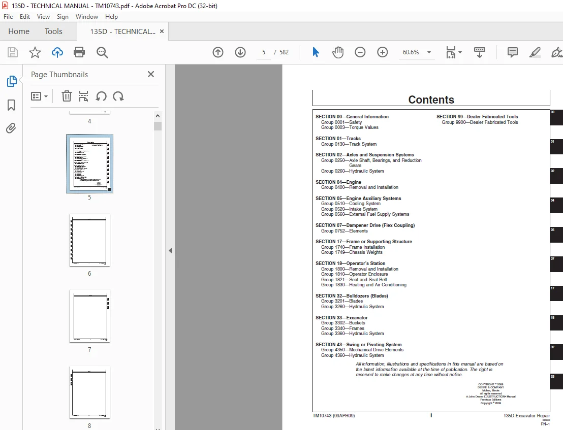
TABLE OF CONTENTS:
John Deere 135D Excavator Repair & TECHNICAL MANUAL TM10743 – PDF DOWNLOAD
Contents 5
General Information 9
Safety 11
Recognize Safety Information 11
Follow Safety Instructions 11
Operate Only If Qualified 11
Wear Protective Equipment 12
Avoid Unauthorized Machine Modifications 12
Add Cab Guarding for Special Uses 13
Inspect Machine 13
Stay Clear of Moving Parts 13
Avoid High-Pressure Fluids 14
Avoid High-Pressure Oils 14
Beware of Exhaust Fumes 15
Prevent Fires 15
Prevent Battery Explosions 15
Handle Chemical Products Safely 16
Dispose of Waste Properly 16
Prepare for Emergencies 16
Use Steps and Handholds Correctly 17
Start Only From Operator’s Seat 17
Use and Maintain Seat Belt 17
Prevent Unintended Machine Movement 18
Avoid Work Site Hazards 19
Keep Riders Off Machine 19
Avoid Backover Accidents 20
Avoid Machine Tip Over 20
Use Special Care When Lifting Objects 21
Add and Operate Attachments Safely 21
Prevent Unintended Detonation of Explosive Devices 21
Park and Prepare for Service Safely 22
Service Cooling System Safely 23
Remove Paint Before Welding or Heating 24
Make Welding Repairs Safely 25
Drive Metal Pins Safely 25
Torque Values 27
Torque Value 27
Metric Bolt and Cap Screw 27
Additional Metric Cap Screw Torque Values 28
Torque Value 30
Unified Inch Bolt and Cap Screw 30
Service Recommendations for 37° Flare and 30° Cone Seat Connectors 31
Service Recommendations for O-Ring Boss Fittings 32
Service Recommendation 34
O-Ring Boss Fittings In Aluminum HousingExcavators 34
Service Recommendations For Flared Connections—Straight or Tapered Threads 36
Service Recommendations For Flat Face O-Ring Seal Fittings 37
Service Recommendation 39
O-Ring Face Seal Fittings with SAE Inch Hex Nut and Stud End for High Pressure 39
O-Ring Face Seal Fittings with Metric Hex Nut and Stud End for Standard Pressure 41
O-Ring Face Seal Fittings with Metric Hex Nut and Stud End for High Pressure 43
Service Recommendations for Metric Series Four Bolt Flange Fitting 45
Service Recommendations For Inch Series Four Bolt Flange Fittings 46
Service Recommendation 47
Inch Series Four Bolt Flange For High Pressure 47
Service Recommendations For Non-Restricted Banjo (Adjustable) Fittings 48
Service Recommendations For O-Ring Boss Fittings With Shoulder 50
Service Recommendation 53
Metric 24 O-Ring Seal DIN 20078 53
Tracks 55
Track System 57
Track Roller Remove and Install 57
Track Roller Disassemble and Assemble 58
Track Roller Pressure Test 61
Track Carrier Roller Remove and Install 62
Inspect Metal Face Seals 64
Track Shoe Remove and Install 65
Track Chain Remove and Install 66
Track Chain Disassemble and Assemble 68
Track Chain Repair 70
Sprocket Remove and Install 72
Front Idler Remove and Install 74
Front Idler Disassemble and Assemble 75
Track Adjuster and Recoil Spring Remove and Install 76
Track Adjuster and Recoil Spring Disassemble and Assemble 78
Track Adjuster Cylinder Disassemble and Assemble 85
Axles and Suspension Systems 87
Axle Shaft, Bearings, and Reduction Gears 89
Travel Gearbox Remove and Install 89
Travel Gearbox Disassemble and Assemble 92
Hydraulic System101
Travel Motor and Park Brake Remove and Install101
Travel Motor and Park Brake Disassemble and Assemble102
Travel Motor Cover Disassemble and Assemble106
Travel Motor Crossover Relief Valve Disassemble and Assemble110
Travel Speed Change Solenoid Valve Remove and Install111
Travel Motor and Park Brake Start-Up Procedure111
Engine113
Removal and Installation115
Engine Remove and Install115
Turbocharger Remove and Install122
Exhaust Manifold Remove and Install126
Valve Cover Remove and Install127
Rocker Arm Assembly Remove and Install129
Rocker Arm Assembly Disassemble and Assemble131
Rocker Arm Assembly Inspection132
Intake Manifold Remove and Install134
Water Pump Remove and Install137
Cylinder Head Remove and Install139
Cylinder Head Disassemble and Assemble154
Cylinder Head Inspection160
Timing Gear Case Remove and Install167
Cylinder Block Disassemble and Assemble174
Cylinder Block Inspection176
Rear Oil Seal Remove and Install179
Camshafts Remove and Install181
Flywheel Remove and Install185
Flywheel Disassemble and Assemble187
Flywheel Housing Remove and Install188
Oil Pan Remove and Install190
Crankshaft Remove and Install193
Crankshaft Disassemble and Assemble199
Crankshaft Inspection199
Main Bearing Inspection201
Piston and Connecting Rod Remove and Install207
Piston and Connecting Rod Disassemble and Assemble209
Piston and Connecting Rod Inspection212
Oil Pump Remove and Install219
Oil Pump Disassemble and Assemble223
Oil Pump Inspection224
Engine Oil Cooler Remove and Install225
Engine Oil Cooler Disassemble and Assemble228
Thermostat Housing Remove and Install229
Thermostat Inspection232
Fuel Injection Pump Remove and Install232
High Pressure Common Rail Remove and Install243
Fuel Injector Remove and Install245
Starter Remove and Install247
Alternator Remove and Install247
Engine Auxiliary Systems249
Cooling System251
Radiator Remove and Install251
Hydraulic Oil Cooler Remove and Install253
Intercooler Remove and Install255
Fuel Cooler Remove and Install257
Fan, Fan Guard, and Fan Shroud Remove and Install257
Intake System261
Air Cleaner Remove and Install261
External Fuel Supply Systems263
Fuel Tank Remove and Install263
Primary Fuel Filter (Water Separator) Remove and Install266
Final Fuel Filter Remove and Install266
Dampener Drive (Flex Coupling)267
Elements269
Dampener Drive (Flex Coupling) Remove and Install269
Frame or Supporting Structure271
Frame Installation273
Welding On Machine273
Welding Repair of Major Structure274
Chassis Weights275
Counterweight Remove and Install275
Operator’s Station277
Removal and Installation279
Cab Remove and Install279
Operator Enclosure289
Sliding Window Remove and Install289
Windowpane Remove and Install290
Windowpanes Dimensions291
Seat and Seat Belt297
Seat Remove and Install297
Seat Belt Remove and Install300
Mechanical Suspension Seat Disassemble and Assemble301
Air Suspension Seat Disassemble and Assemble303
Left and Right Console Covers Remove and Install304
Heating and Air Conditioning309
Refrigerant Cautions and Proper Handling309
Flush and Purge Air Conditioner System311
R134a Refrigerant Oil Information314
R134a Refrigerant Recovery/Recycling and Charging Station Installation Procedure315
Recover R134a Refrigerant316
Evacuate R134a System317
Charge R134a System318
Compressor Remove and Install319
Condenser Remove and Install320
Heater and Air Conditioner Remove and Install323
Receiver-Dryer Remove and Install328
Bulldozers (Blades)331
Blades334
Blade Remove and Install334
Hydraulic System337
Blade Pump Remove and Install337
Blade Pump Disassemble and Assemble339
Blade Pump Pressure Relief Valve Remove and Install342
Blade Control Valve Remove and Install343
Blade Control Valve Disassemble and Assemble346
Blade Pilot Controller Remove and Install347
Blade Pilot Controller Disassemble and Assemble349
Blade Cylinder Remove and Install351
Blade Cylinder Disassemble and Assemble356
Excavator361
Buckets363
Bucket Remove and Install363
Bucket Pin-Up Data364
Frames367
Bucket Links Remove and Install367
Arm Remove and Install368
Boom Remove and Install373
Inspect Pins, Bushings and Bosses—Front Attachment376
Bushings and Seal Remove and Install379
Hydraulic System381
Apply Vacuum to Hydraulic Oil Tank381
Hydraulic Oil Cleanup Procedure Using Portable Filter Caddy383
Pump 1 and 2 Remove and Install384
Pump 1 and 2 Disassemble and Assemble389
Pump 1 and 2 Inspection403
Pump 1 and 2 Start-Up Procedure405
Pump 1 and 2 Regulator Remove and Install407
Pump 1 and 2 Regulator Disassemble and Assemble409
Pilot Pump Remove and Install414
Pilot Pump Disassemble and Assemble415
Pilot Pressure Regulating Valve and Filter Remove and Install418
Pilot Pressure Regulating Valve and Filter Disassemble and Assemble419
Pilot Shutoff Solenoid Valve Remove and Install419
Pilot Shutoff Solenoid Valve Disassemble and Assemble422
Solenoid Valve Manifold Remove and Install423
Travel Speed and Arm Regenerative Solenoid Valve Disassemble and Assemble426
Pilot Valve (Left and Right) Remove and Install428
Pilot Valve (Left and Right) Disassemble and Assemble432
Travel Pilot Valve Remove and Install434
Travel Pilot Valve Disassemble and Assemble436
Pilot Signal Manifold Remove and Install438
Pilot Signal Manifold Disassemble and Assemble442
Control Valve Remove and Install449
Control Valve Separation456
Control Valve (5-Spool) Disassemble and Assemble457
Control Valve (4-Spool) Disassemble and Assemble468
Hydraulic Oil Tank Remove and Install480
Hydraulic Oil Tank Disassemble and Assemble484
Restriction Valve Remove and Install488
Hydraulic Oil Cooler Bypass Valve Remove and Install490
Boom Cylinder Remove and Install491
Boom Cylinder Disassemble and Assemble496
Arm Cylinder Remove and Install498
Arm Cylinder Disassemble and Assemble504
Bucket Cylinder Remove and Install506
Bucket Cylinder Disassemble and Assemble510
Hydraulic Cylinder Bleed Procedure512
Swing or Pivoting System513
Mechanical Drive Elements515
Swing Gearbox Remove and Install515
Swing Gearbox Disassemble and Assemble518
Swing Gearbox Start-Up Procedure523
Upperstructure Remove and Install524
Swing Bearing Remove and Install527
Swing Bearing Disassemble and Assemble531
Swing Bearing Upper Seal Install535
Swing Bearing Lower Seal Install536
Hydraulic System537
Center Joint Remove and Install537
Center Joint Disassemble and Assemble541
Center Joint Air Test542
Swing Motor and Park Brake Remove and Install543
Swing Motor and Park Brake Disassemble and Assemble546
Swing Motor and Park Brake Inspection548
Swing Motor and Park Brake Start-Up Procedure553
Crossover Relief Valve and Make-Up Check Valve Remove and Install553
Swing Park Brake Release Valve Remove and Install556
Dealer Fabricated Tools557
Dealer Fabricated Tools559
DF1063 Lift Bracket559
ST4920 Track Recoil Spring Disassembly and Assembly Tool561
DFT1087 Track Recoil Spring Disassembly and Assembly Guard Tool565
DFT1112A Spacer566
DFT1130 Adapter567
DFT1036A Travel Gearbox Nut Wrench568
DFT1109 Holding Bar569
DFT1303 Center Joint (Rotary Manifold) Lifting Tool570
DFT1304 Guide Pin570
DFT1119 Pump Support571
DFT1237 Swing Gearbox Nut Spanner Wrench572
Page Numbers 5
Section 00 9
Group 0001 11
S.M 6/1/25