John Deere 160DLC Excavator Service Manual PDF Download
Original price was: $86.95.$27.95Current price is: $27.95.
John Deere 160DLC Excavator Repair Manual – PDF DOWNLOAD
Description
John Deere 160DLC Excavator Repair Manual – PDF DOWNLOAD
DESCRIPTION:
John Deere 160DLC Excavator Repair Manual – PDF DOWNLOAD
For complete service information also see:
160DLC Excavator Operation and Tests . . . TM10088
160DLC Excavator Operator’s Manual . . . . . OMT226911
POWERTECH 4.5L/6.8L POWERTECH E
6.8L Diesel Engines—Base Engine . . . . . . . CTM104
POWERTECH E 6.8L Diesel
Engines—Level 16 Electronic Fuel System
with Denso HPCR . . . . . . . . . . . . . . . . . . . . . CTM502
Alternators and Starter Motors. . . . . . . . . . . CTM77
Undercarriage Appraisal Manual . . . . . . . . . SP326
Super Caddy Oil Cleanup Procedure . . . . . . CTM310
Foreword :
This manual is written for an experienced technician. Essential tools required in performing certain service work are identified in this manual and are recommended for use. Live with safety: Read the safety messages in the introduction of this manual and the cautions presented throughout the text of the manual.
- This is the safety-alert symbol. When you see this symbol on the machine or in this manual, be alert to the potential for personal injury. Technical manuals are divided in two parts: repair and operation and tests. Repair sections tell how to repair the components. Operation and tests sections help you identify the majority of routine failures quickly. Information is organized in groups for the various components requiring service instruction.
- At the beginning of each group are summary listings of all applicable essential tools, service equipment and tools, other materials needed to do the job, service parts kits, specifications, wear tolerances, and torque values. Technical Manuals are concise guides for specific machines.
- They are on-the-job guides containing only the vital information needed for diagnosis, analysis, testing, and repair. Fundamental service information is available from other sources covering basic theory of operation, fundamentals of troubleshooting, general maintenance, and basic type of failures and their causes.
TABLE OF CONTENTS:
John Deere 160DLC Excavator Repair Manual – PDF DOWNLOAD
Contents 5
General Information 9
Safety 11
Recognize Safety Information 11
Follow Safety Instructions 11
Operate Only If Qualified 11
Wear Protective Equipment 12
Avoid Unauthorized Machine Modifications 12
Add Cab Guarding for Special Uses 13
Inspect Machine 13
Stay Clear of Moving Parts 13
Avoid High-Pressure Fluids 14
Avoid High-Pressure Oils 14
Beware of Exhaust Fumes 15
Prevent Fires 15
Prevent Battery Explosions 15
Handle Chemical Products Safely 16
Dispose of Waste Properly 16
Prepare for Emergencies 16
Use Steps and Handholds Correctly 17
Start Only From Operator’s Seat 17
Use and Maintain Seat Belt 17
Prevent Unintended Machine Movement 18
Avoid Work Site Hazards 19
Keep Riders Off Machine 19
Avoid Backover Accidents 20
Avoid Machine Tip Over 20
Use Special Care When Lifting Objects 21
Add and Operate Attachments Safely 21
Park and Prepare for Service Safely 22
Service Cooling System Safely 22
Remove Paint Before Welding or Heating 23
Make Welding Repairs Safely 24
Drive Metal Pins Safely 24
Torque Values 25
Torque Value 25
Metric Bolt and Cap Screw 25
Additional Metric Cap Screw Torque Values 26
Torque Value 28
Unified Inch Bolt and Cap Screw 28
Service Recommendations for 37° Flare and 30° Cone Seat Connectors 29
Service Recommendations for O-Ring Boss Fittings 30
Service Recommendation 32
O-Ring Boss Fittings In Aluminum Housing—Excavators 32
Service Recommendations For Flared Connections—Straight or Tapered Threads 34
Service Recommendations For Flat Face O-Ring Seal Fittings 35
Service Recommendation 36
O-Ring Face Seal Fittings with SAE Inch Hex Nut and Stud End for High Pressure 36
O-Ring Face Seal Fittings with Metric Hex Nut and Stud End for Standard Pressure 38
O-Ring Face Seal Fittings with Metric Hex Nut and Stud End for High Pressure 40
Service Recommendations for Metric Series Four Bolt Flange Fitting 42
Service Recommendations For Inch Series Four Bolt Flange Fittings 43
Service Recommendation 44
Inch Series Four Bolt Flange For High Pressure 44
Tracks 45
Track System 47
Track Roller Remove and Install 47
Track Roller Disassemble and Assemble 49
Track Roller Pressure Test 51
Track Carrier Roller Remove and Install 52
Metal Face Seals Repair 54
Track Shoe Remove and Install 57
Track Chain Remove and Install 57
Track Chain Disassemble and Assemble 62
Track Chain Repair 63
Sprocket Remove and Install 65
Front Idler Remove and Install 66
Front Idler Disassemble and Assemble 67
Track Adjuster and Recoil Spring Remove and Install 69
Track Adjuster and Recoil Spring Disassemble and Assemble 71
Track Adjuster Cylinder Disassemble and Assemble 76
Axles, Differentials and Suspension Systems 79
Axle Shaft, Bearings, and Reduction Gears 81
Travel Gearbox Remove and Install 81
Travel Gearbox Disassemble and Assemble 84
Hydraulic System 92
Travel Motor and Park Brake Remove and Install 92
Travel Motor and Park Brake Disassemble and Assemble100
Counterbalance Valve Remove and Install103
Crossover Relief Valve Remove and Install105
Make-Up Check Valve Remove and Install107
Travel Speed Change Valve Remove and Install109
Travel Motor and Park Brake Start-Up Procedure111
Engine113
Removal and Installation115
Engine Remove and Install115
Engine Auxiliary System125
Cooling System127
Radiator Remove and Install127
Hydraulic Oil Cooler Remove and Install130
Intercooler Remove and Install132
Fuel Cooler Remove and Install137
Cooling Package Remove and Install137
Fan, Fan Guard, and Fan Shroud Remove and Install145
Coolant Surge Tank Remove and Install150
Intake System151
Air Cleaner Remove and Install151
External Fuel Supply System153
Fuel Tank Remove and Install153
Primary Fuel Filter (Water Separator) Remove and Install155
Final Fuel Filter Remove and Install156
Dampener Drive (Flex Coupling)157
Elements159
Dampener Drive (Flex Coupling) Remove and Install159
Frame or Supporting Structure161
Frame Installation163
Welding On Machine163
Welding Repair of Major Structure165
Chassis Weights167
Counterweight Remove and Install167
Operator’s Station169
Removal and Installation171
Cab Remove and Install171
Operator Enclosure179
Sliding Windows Remove and Install179
Windowpanes Remove and Install180
Windowpanes Dimensions181
Seat and Seat Belt187
Seat Remove and Install187
Seat Belt Remove and Install188
Mechanical Suspension Seat Disassemble and Assemble189
Air Suspension Seat Disassemble and Assemble190
Left and Right Console Covers Remove and Install191
Heating and Air Conditioning195
Refrigerant Cautions and Proper Handling195
Flush and Purge Air Conditioner System197
R134a Refrigerant Oil Information200
R134a Refrigerant Recovery/Recycling and Charging Station Installation Procedure201
Recover R134a Refrigerant202
Evacuate R134a System203
Charge R134a System204
Compressor Remove and Install205
Condenser Remove and Install205
Heater and Air Conditioner Remove and Install207
Receiver-Dryer Remove and Install211
Excavator213
Buckets215
Bucket Remove and Install215
Bucket Pin-Up Data216
Frames219
Bucket Links Remove and Install219
Arm Remove and Install221
Boom Remove and Install224
Inspect Pins, Bushings and Bosses—Front Attachment229
Bushings and Seal Remove and Install232
Hydraulic System233
Apply Vacuum to Hydraulic Oil Tank233
Hydraulic Oil Cleanup Procedure Using Portable Filter Caddy235
Pump 1 and 2 Remove and Install236
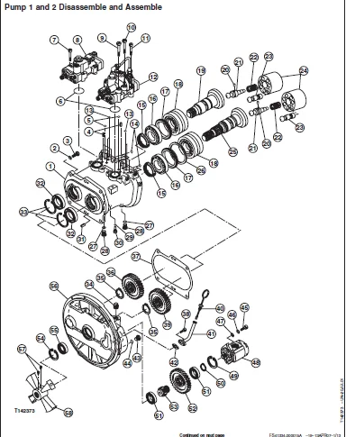
Pump 1 and 2 Disassemble and Assemble242
Pump 1 and 2 Inspection254
Pump 1 and 2 Start-Up Procedure257
Pump 1 and 2 Regulator Remove and Install258
Pump 1 and 2 Regulator Disassemble and Assemble260
Pilot Pump Remove and Install262
Pilot Pump Disassemble and Assemble264
Pilot Pump Drive Shaft Remove and Install266
Pilot Pressure Regulating Valve and Filter Remove and Install267
Pilot Pressure Regulating Valve and Filter Disassemble and Assemble268
Pilot Shutoff Solenoid Valve Remove and Install268
Pilot Shutoff Solenoid Valve Disassemble and Assemble270
Fan Drive Pump Remove and Install271
Fan Drive Motor Remove and Install272
Fan Drive Control Valve Remove and Install275
Solenoid Valve Manifold Remove and Install276
Solenoid Valve Remove and Install—Power Dig (SG), Travel Speed (SI), Boom Mode (SC), and Boom Flow Rate (SF)278
Pilot Valve (Left and Right) Remove and Install279
Pilot Valve (Left and Right) Disassemble and Assemble282
Travel Pilot Valve Remove and Install284
Travel Pilot Valve Disassemble and Assemble286
Pilot Signal Manifold Remove and Install288
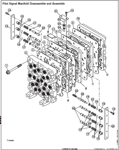
Pilot Signal Manifold Disassemble and Assemble290
Control Valve Remove and Install293
Control Valve (5-Spool) Disassemble and Assemble295
Control Valve (4-Spool) Disassemble and Assemble303
Hydraulic Oil Tank Remove and Install308
Hydraulic Oil Tank Disassemble and Assemble312
Restriction Valve Remove and Install313
Hydraulic Oil Cooler Bypass Valve Remove and Install315
Boom Cylinder Remove and Install317
Boom Cylinder Disassemble and Assemble321
Arm Cylinder Remove and Install323
Arm Cylinder Disassemble and Assemble328
Bucket Cylinder Remove and Install331
Bucket Cylinder Disassemble and Assemble335
Hydraulic Cylinder Bleed Procedure338
Swing or Pivoting System339
Mechanical Drive Elements341
Swing Gearbox Remove and Install341
Swing Gearbox Disassemble and Assemble344
Swing Gearbox Start-Up Procedure351
Upperstructure Remove And Install351
Swing Bearing Remove and Install354
Swing Bearing Disassemble and Assemble356
Swing Bearing Upper Seal Install359
Swing Bearing Lower Seal Install360
Hydraulic System361
Center Joint Remove and Install361
Center Joint Disassemble and Assemble364
Center Joint Air Test365
Swing Motor and Park Brake Remove and Install366
Swing Motor and Park Brake Disassemble370
Swing Motor and Park Brake Inspection372
Swing Motor and Park Brake Assemble374
Swing Motor and Park Brake Start-Up Procedure376
Crossover Relief Valve and Make-Up Check Valve Remove and Install377
Make-Up Check Valve Disassemble and Assemble378
Swing Park Brake Release Valve Remove and Install379
Dealer Fabricated Tools381
Dealer Fabricated Tools383
DF1063 Lift Bracket383
ST4920 Track Recoil Spring Disassembly and Assembly Tool385
DFT1087 Track Recoil Spring Disassembly and Assembly Guard Tool389
DFT1110 Spacer390
DFT1130 Adapter391
DFT1036A Travel Gearbox Nut Wrench392
DF1038 Torque Adapter393
DFT1109 Holding Bar394
Center Joint (Rotary Manifold) Lifting Tool395
DFT1144 Guide Pin395
DFT1119 Pump Support396
DFT1220 Swing Gearbox Nut Spanner Wrench398
IMAGES PREVIEW OF THE MANUAL:
JOHN DEERE 160DLC EXCAVATOR REPAIR MANUAL – PDF DOWNLOAD:
PLEASE NOTE:
- This is not a physical manual but a digital manual – meaning no physical copy will be couriered to you. The manual can be yours in the next 2 mins as once you make the payment, you will be directed to the download page IMMEDIATELY.
- This is the same manual used by the dealersinorder to diagnose your vehicle of its faults.
- Require some other service manual or have any queries: please WRITE to us at [email protected]
S.V