John Deere 230LCR & 230LCRD Hydraulic Excavator Technical Manual – PDF DOWNLOAD
Original price was: $75.95.$32.95Current price is: $32.95.
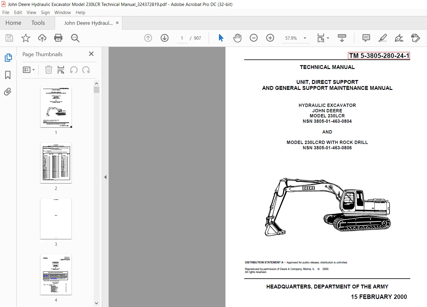
John Deere 230LCR & 230LCRD Hydraulic Excavator Technical Manual – PDF DOWNLOAD
UNIT, DIRECT SUPPORT
AND GENERAL SUPPORT MAINTENANCE MANUAL
HYDRAULIC EXCAVATOR
JOHN DEERE
MODEL 230LCR
NSN 3805-01-463-0804
AND
MODEL 230LCRD WITH ROCK DRILL
NSN 3805-01-463-0806
Description
John Deere 230LCR & 230LCRD Hydraulic Excavator Technical Manual – PDF DOWNLOAD
DESCRIPTION:
John Deere 230LCR & 230LCRD Hydraulic Excavator Technical Manual – PDF DOWNLOAD
UNIT, DIRECT SUPPORT
AND GENERAL SUPPORT MAINTENANCE MANUAL
HYDRAULIC EXCAVATOR
JOHN DEERE
MODEL 230LCR
NSN 3805-01-463-0804
AND
MODEL 230LCRD WITH ROCK DRILL
NSN 3805-01-463-0806
INTRODUCTION:
READ THIS MANUAL carefully to learn how to operate and service your machine correctly. Failure to do so could result in personal injury or equipment damage. This manual and safety signs on your machine may also be available in other languages. (See your John Deere dealer to order.) THIS MANUAL SHOULD BE CONSIDERED a permanent part of your machine and should remain with the machine when you sell it.
- MEASUREMENTS in this manual are given in both metric and customary U.S. unit equivalents. Use only correct replacement parts and fasteners.
- Metric and inch fasteners may require a specific metric or inch wrench. RIGHT-HAND AND LEFT-HAND sides are determined by facing in the direction of forward travel.
TABLE OF CONTENTS:
John Deere 230LCR & 230LCRD Hydraulic Excavator Technical Manual – PDF DOWNLOAD
Chapter 1 Section 9000 General Information
01 Safety1-1
Follow Safe Procedures1-1
Prepare for Emergencies 1-1
Handle Fluids Safely—Avoid Fires 1-1
Prevent Battery Explosions 1-2
Handle Chemical Products Safely1-2
Prevent Acid Burns 1-3
Avoid High-Pressure Fluids 1-4
Warn Others of Service Work 1-4
Park Machine Safely 1-5
Support Machine Properly1-5
Operate Only From Operator’s Seat1-5
TM 5-3805-280-24-1
Stay Clear of Moving Parts 1-6
Avoid Power Lines1-6
Use Handholds and Steps 1-6
Keep Riders Off Machine1-7
Move and Operate Machine Safely 1-7
Wear Protective Clothing 1-7
Protect Against Flying Debris 1-8
Protect Against Noise1-8
Illuminate Work Area Safely1-8
Service Machines Safely 1-8
Remove Paint Before Welding or Heating1-9
Avoid Heating Near Pressurized Fluid Lines 1-9
Beware of Exhaust Fumes1-10
Use Proper Lifting Equipment1-10
Service Cooling System Safely 1-10
Dispose of Waste Properly1-11
Work in a Clean Area1-11
Use Tools Properly1-12
Replace Safety Signs 1-12
Live With Safety 1-12
Battery Terminals, Lifting Equipment, Dry Cleaning, Solvent
and Compressed Air 1-13
Compressor Equipment Hazards 1-14
Rock Drill Precautions 1-16
02 General Specifications 1-19
03 Torque Values1-20
Unified Inch Bolt and Cap Screw Torque Values 1-20
Metric Bolt and Cap Screw Torque Values1-21
Additional Metric Cap Screw Torque Values 1-22
Check Oil Lines and Fittings1-23
Service Recommendations for O-Ring Boss Fittings1-24
Service Recommendations for Flat Face O-Ring Seal Fittings 1-26
Service Recommendations for 37° Flare and
30° Cone Seat Connectors 1-27
Service Recommendations for Flared Connections—
Straight or Tapered Threads 1-28
Service Recommendations for Inch Series Four Bolt Flange Fittings1-29
Service Recommendations for Metric Series Four Bolt Flange Fitting1-31
04 Fuels and Lubricants1-32
Diesel Fuel 1-32
Lubricity of Diesel Fuels1-32
Low Sulfur Diesel Fuel Conditioner 1-33
Diesel Fuel Storage 1-33
Fuel Tank 1-34
Do Not Use Galvanized Containers 1-34
Diesel Engine and Pump Gearbox Oils 1-35
Hydraulic Oil1-36
Swing Gearbox and Propel Gearbox Oils1-37
Track Roller, Front Idler, and Carrier Roller Oil 1-37
Track Adjuster, Working Tool Pivot, Swing Bearing, and
Swing Bearing Gear Grease1-38
Oil Filters 1-38
Rock Drill Lubricants Specifications 1-39
Lubricant Storage 1-41
Alternative and Synthetic Lubricants 1-41
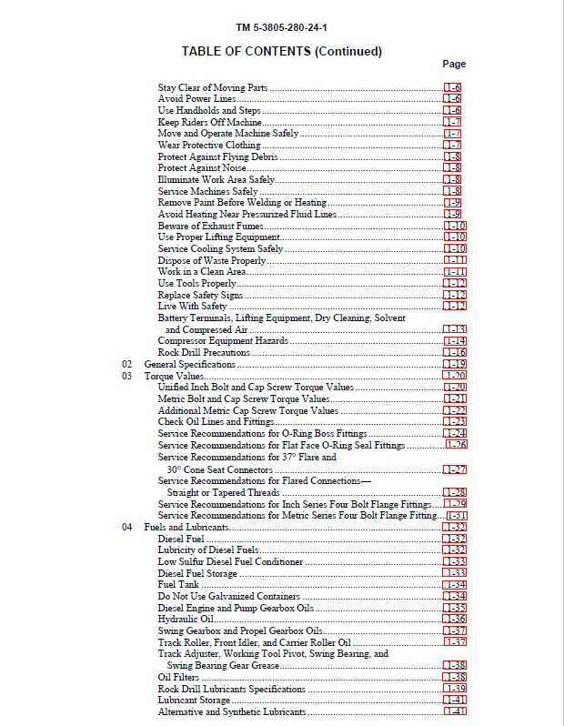
TM 5-3805-280-24-1
TABLE OF CONTENTS (Continued)
Page
iii
Mixing of Lubricants1-42
Air Compressor Lubrication1-43
Chapter 2 Section 9005 Operational Checkout Procedure
10 Operational Checkout Procedure2-1
Operational Checkout2-1
Operator Station Checks—Key Switch On, Engine Off 2-2
Operator Station Checks—Engine On2-5
Hydraulic System Checks 2-11
Undercarriage Checks 2-19
Accessories Checks 2-21
Seat, Doors, Windows, Latches, and Locks Checks2-23
Engine Cooling System Checks 2-29
Air Intake System Checks 2-33
Fuel System Checks 2-36
Visual Inspection2-38
Chapter 3 Section 9010 Engine
05 Theory of Operation 3-1
Engine—Sectional View3-1
Fan Drive3-2
Engine Speed Control
System Operation3-3
Engine RPM Dial3-5
E (Economy) Mode3-7
HP (High Power) Mode 3-8
Auto-Idle Mode 3-10
Engine Speed Learning3-11
10 System Operational Checks3-13
Engine Operational Checks 3-13
Cooling System Checks3-13
Air Intake System Checks 3-18
Lubrication System Checks3-21
Fuel System Checks 3-23
Engine Speed and Performance Checks 3-25
15 Diagnostic Information3-28
Diagnose Engine Malfunctions 3-28
20 Adjustments 3-40
JT05801 Clamp-On Electronic Tachometer Installation3-40
Fuel Shut-Off Solenoid Linkage, Check and Adjust 3-41
Engine Speed Check3-44
Injection Pump Fast and Slow Idle Stops3-45
Engine Control Motor and Sensor3-48
Engine Speed Learning Procedure 3-49
Cooling System Fill and Deaeration3-51
25 Tests3-52
Fuel Line Leakage3-52
Air Filter Restriction Indicator Switch 3-53
Air Intake System Leakage 3-54
Radiator Air Flow3-55
Engine Power Test Using Turbocharger Boost Pressure3-58
Torsional Dampener, Inspect 3-62
TM 5-3805-280-24-1
TABLE OF CONTENTS (Continued)
Page
iv
Chapter 4 Section 9015 Electrical System
05 System Information 4-1
Visually Inspect Electrical System4-1
Circuit Malfunctions
Circuit Malfunctions4-2
Definition4-3
Location 4-8
Troubleshooting4-9
Circuit Shorted to Power and Circuit Shorted to Itself4-11
Using Test Equipment
Multimeter 4-14
Seven Step Electrical Test Procedure 4-15
System Functional Schematic Information4-16
Reading a System Functional Schematic Diagram4-17
Reading a Harness Component Location Diagram 4-19
Electrical Schematic Symbols 4-23
10 System Diagrams4-26
Fuse Specifications4-26
Fuse (Blade-Type) Color Codes4-27
Component Identification Table4-27
Functional Schematic and Component Location Legend4-29
System Functional Schematic Section Legend4-33
System Functional Schematic (SE1—SE3)4-34
System Functional Schematic (SE4—SE6)4-35
System Functional Schematic (SE7—SE9)4-36
System Functional Schematic (SE10—SE12)4-37
System Functional Schematic (SE13—SE15)4-38
System Functional Schematic (SE16—SE18)4-39
System Functional Schematic (SE19) 4-40
Engine and Frame Harness (W1)
Component Location 4-41
Connectors, Wire and Pin Location 4-45
Air Compressor and Rock Drill Harness (W10) Component Location4-49
Cab Harness (W2)
Component Location 4-50
Component Location—Detail A (Harness Mating Connectors) 4-51
Component Location—Detail B (Fuse Block)4-53
Connectors, Wire and Pin Location 4-54
Monitor and Relay Harness (W3)
Component Location 4-60
Component Location—Detail A (Monitor Controller Connectors) 4-61
Component Location—Detail B (Monitor Controller Indicators) 4-62
Connectors, Wire and Pin Location 4-63
Air Conditioner Harness (W9)
Component Location—See Group 9031-15 4-65
Connectors, Wire and Pin Location—See Group 9031-154-65
15 Sub-System Diagnostics 4-66
Power Circuit
Operational Information 4-66
Theory of Operation 4-67
Schematic4-68
Power Circuit Diagnostic Procedures4-69
Charging Circuit
Operational Information 4-73
Theory of Operation 4-73
TM 5-3805-280-24-1
TABLE OF CONTENTS (Continued)
Page
v
Schematic4-74
Alternator Theory of Operation4-75
Charging Circuit Diagnostic Procedures 4-76
Starting and Fuel Shutoff Circuit
Operational Information 4-80
Theory of Operation 4-80
Schematic4-81
Starting Circuit Diagnostic Procedures 4-82
Windshield Wiper and Washer Circuit
Operational Information 4-88
Theory of Operation 4-89
Schematic4-91
Windshield Wiper and Washer Circuit Diagnostic Procedures4-92
Work and Drive Light Circuit
Operational Information 4-97
Theory of Operation 4-97
Schematic4-98
Work and Drive Light Circuit Diagnostic Procedures 4-99
Accessory Circuits
Operational Information 4-102
Theory of Operation 4-102
Schematic4-103
Accessory Circuits Diagnostic Procedures4-104
Quick Hitch Circuit
Operational Information 4-106
Theory of Operation 4-106
Schematic4-107
Quick Hitch Circuit Diagnostic Procedures 4-107
Heater Circuit (Machines Without Air Conditioner)4-108
Heater Circuit (Machines With Air Conditioner)4-109
Monitor Controller and Display Circuit
Specifications4-110
Operational Information 4-111
Theory of Operation 4-112
Schematic4-115
Monitor Controller and Display Circuit Diagnostic Procedures 4-116
Engine and Pump Controller Circuit
Operational Information 4-133
Theory of Operation 4-134
Schematic4-136
Engine and Pump Controller Circuit Diagnostic Procedures 4-137
Travel Alarm Circuit
Operational Information 4-160
Theory of Operation 4-160
Schematic4-161
Travel Alarm Circuit Diagnostic Procedures 4-162
Overload Alarm Circuit
Operational Information 4-165
Theory of Operation 4-165
Schematic4-166
Overload Alarm Circuit Diagnostic Procedures4-166
20 References 4-169
Battery
Operation 4-169
Specifications4-170
TM 5-3805-280-24-1
TABLE OF CONTENTS (Continued)
Page
vi
Diagnose Malfunctions 4-171
Check Electrolyte Level and Terminals4-172
Batteries
Procedure for Testing 4-174
Using Booster Batteries—24 Volt System4-175
Replacing 4-176
Adding 12 or 24 Volt Accessories 4-177
Travel Alarm, Changing Volume 4-178
Test Harness
Proportional Solenoid 4-179
Pump Control4-179
Pump Pressure Sensor4-179
Chapter 5 Section 9020 Power Train
05 Theory of Operation 5-1
Track Adjuster5-1
Propel Gearbox5-2
15 Diagnostic Information5-4
Diagnose Undercarriage Components Malfunctions5-4
Track Chain
Measure Bushing Wear5-6
Measure Link Wear 5-7
Measure Pitch 5-8
Track Shoe Grouser
Measure Wear (SN —599999) 5-9
Measure Wear (SN 600000—) 5-10
Track Roller, Measure Wear 5-11
Track Carrier Roller, Measure Wear5-12
Front Idler, Measure Wear 5-13
Swing Bearing, Measure Wear5-14
20 Adjustments 5-16
Track Sag 5-16
Chapter 6 Section 9025 Hydraulic System
05 Theory of Operation 6-1
Hydraulic System Diagram6-1
Pilot Pump Operation 6-2
Pilot Pressure Regulating Valve and Filter Operation6-3
Pilot Shut-Off Valve Operation6-4
Pilot Controller
Neutral 6-6
Metering and Full Stroke 6-7
Propel Pilot Controller 6-8
Pilot Controller Operation of Control Valve 6-10
Flow Regulator Valve 6-11
Hydraulic Pump and Drive Gearbox 6-13
Hydraulic Pump Operation6-15
Hydraulic Pump Regulator
Component Operation6-17
Operation 6-19
Increasing, Maximum, and Decreasing 6-21
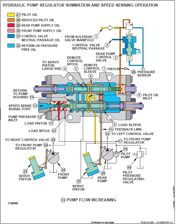
Summation and Speed Sensing6-23
Proportional Solenoid Valve
Manifold Operation 6-25
TM 5-3805-280-24-1
TABLE OF CONTENTS (Continued)
Page
vii
Arm Regenerative, Speed Sense, Propel Speed Change,
and Power Boost 6-27
Engine Speed Sensing Control Circuit 6-29
Control Valve
Component Identification Operation 6-30
Circuit Schematic6-34
Pilot Pressure Signal Passage 6-36
Neutral and Power Passages 6-38
System Relief and Power Boost Valve6-40
Power Boost Control Circuit 6-41
Circuit Relief Valve 6-42
Pump Control Valve6-43
Flow Combiner Valve 6-45
Arm Regenerative Valve 6-47
Boom and Arm Reduced Leakage Valves6-49
Bucket Flow Control Valve6-50
Propel Flow Control Valve6-52
Propel-Boom Down Selector Valve 6-53
Boom Regenerative Valve6-54
Propel and Arm In Combined 6-55
Swing and Boom Up Combined6-57
Swing Gearbox6-59
Swing Motor
Operation 6-61
Crossover Relief Valve6-63
Make-Up Valve 6-64
Park Brake Release Valve6-65
Rotary Manifold 6-67
Propel Motor
Operation 6-68
Slow Speed 6-70
Fast Speed6-71
Speed Change Circuit 6-72
Park Brake Valve Housing 6-74
Park Brake Release Circuit 6-76
Counterbalance Valve6-78
Cylinder Boom, Arm, and Bucket6-80
Return Filter 6-81
Boom Cylinder Controlled Load Lowering Valve Operation 6-82
Auxiliary Hydraulics Operation 6-84
Hydraulic System Circuit Symbols 6-86
Schematic
Pilot Controllers Circuit6-87
Hydraulic Pump and Control Valve6-88
Swing and Propel Motor6-89
15 Diagnostic Information6-90
Diagnostic Procedure 6-90
Diagnose Malfunctions
Electronic and Control Valve Component 6-91
Hydraulic System6-101
Pilot Circuit6-104
Dig Circuit 6-106
Swing Circuit 6-108
Propel System6-110
Control Lever Pattern Conversion6-113
TM 5-3805-280-24-1
TABLE OF CONTENTS (Continued)
Page
viii
Control Valve Line Identification
Left Front 6-114
Right Rear6-116
Bottom 6-118
Control Valve Component Identification
Left Front 6-119
Right Rear6-121
Bottom 6-123
Component Location
Main Hydraulic System6-124
Pilot Controllers-to-Flow Regulator—SAE Pattern6-125
Pilot Controllers-to-Flow Regulator—John Deere Pattern 6-126
Pilot Flow Regulator-to-Control Valve 6-127
Propel System6-128
Pressure and Return System 6-129
20 Adjustment 6-130
Pilot Shut-Off Valve Linkage6-130
25 Tests6-131
Laptop Computer General Description6-131
Excavator Diagnostics Program
Overview 6-131
Install 6-132
Uninstall6-137
Starting6-137
Feature—Service Codes 6-141
Feature—Monitor Data6-143
Feature—Saving Monitor Data6-145
Special Function—Engine Speed Adjustment 6-146
Service Codes List 6-150
Monitor Data Items6-151
Special Function—Engine Speed Factory Settings Parameters6-152
Engine Speed to Pump Flow Rate Chart 6-153
Excavator Diagnostics Program Troubleshooting6-155
Reading Service Codes Without Excavator Diagnostics Program 6-156
Engine and Pump Controller Functions 6-158
JT05801Clamp-On Electronic Tachometer Installation6-159
JT05800 Digital Thermometer Installation 6-160
JT02156A Digital Pressure and Temperature Analyzer Installation 6-160
Start-Up Procedure
Hydraulic Pump6-161
Swing Motor 6-162
Swing Gearbox 6-163
Propel Motor6-164
Hydraulic Oil Filter Inspection Procedure 6-164
Hydraulic Oil Cleanup Procedure Using Portable Filter Caddy6-165
Hydraulic System Warm-Up Procedure6-166
Lower Boom With Engine Stopped (Using Boom Cylinder
Load Lowering Valve)6-167
Lower Boom With Engine Stopped (When Not Equipped With
Boom Cylinder Load Lowering Valve) 6-169
Harness Test
Arm Regenerative Proportional Solenoid Valve (SC) 6-171
Speed Sensing Solenoid Valve (SD)6-173
Propel Speed Change Proportional Solenoid Valve (SI) 6-175
Power Boost Proportional Solenoid Valve (SG)6-177
TM 5-3805-280-24-1
TABLE OF CONTENTS (Continued)
Page
ix
Engine Control Sensor (EC Sensor) 6-179
Engine Control Motor (EC Motor) 6-182
Miscellaneous Component6-184
Cycle Time 6-185
Swing Dynamic Braking 6-188
Pilot Pressure Regulating Valve6-190
Valve Spool Actuating Pilot Pressure 6-194
System Relief and Power Boost Valve6-197
Circuit Relief Valve 6-202
Swing Motor Crossover Relief Valve 6-208
Propel Motor Crossover Relief Valve 6-211
Proportional Solenoid Valve 6-215
Pump Control Valve6-220
Hydraulic Pump Regulator
Adjustments 6-225
Minimum Flow6-228
Maximum Flow 6-232
Engine Pulldown6-235
Hydraulic Pump Flow 6-248
Pilot Pump Flow6-252
Propel System Tracking 6-255
Cylinder Drift—Boom, Arm, and Bucket 6-257
Swing Motor Leakage 6-260
Propel Motor Leakage6-264
Boom Cylinder Controlled Load Lowering Valve 6-268
Hose Reel 6-270
Chapter 7 Section 9031 Air Conditioning System
05 Theory of Operation 7-1
Proper Refrigerant Handling 7-1
R134a Refrigerant Cautions 7-1
Refrigerant Theory of Operation 7-2
Heater and Air Conditioner Circuit
Operational Information 7-3
Theory of Operation 7-4
Functional Schematic7-5
Heater Circuit (Machines Without Air Conditioner)
Operational Information 7-6
Theory of Operation 7-6
Functional Schematic7-7
Receiver/Dryer Operation 7-8
Compressor Relief Valve Operation 7-9
Temperature Control 7-9
10 System Operational Checks7-10
Air Conditioning Operational Checks 7-10
Visual Inspection of Components 7-10
System Operating Checks 7-12
Heater Circuit Checks (Machines Equipped With Heater Only)7-14
Heater and Air Conditioner Circuit Checks 7-15
15 Diagnostic Information7-17
Diagnose Air Conditioning Electrical Malfunctions 7-17
Air Conditioner Harness (W9)
Component Location 7-18
Connectors, Wire and Pin Location 7-20
TM 5-3805-280-24-1
TABLE OF CONTENTS (Continued)
Page
x
20 Adjustments 7-22
Refrigerant
Proper Handling7-22
R134a Cautions7-22
Compressor
R134a Oil Charge Check 7-23
R134a Oil Removal 7-23
R134a Component Oil Charge 7-24
R134a Refrigerant Recovery, Recycling, and
Charging Station Installation Procedure 7-26
R134a System
Recover7-27
Evacuate7-28
Charge7-31
Compressor Belt, Check and Adjust Tension7-33
25 Tests7-34
Refrigerant
Proper Handling7-34
R134a Cautions7-34
R134a Air Conditioning System Test7-35
Operating Pressure Diagnostic Chart 7-38
High and Low Pressure Switch Test 7-39
Leak Testing7-40
Refrigerant Hoses and Tubing Inspection 7-41
Chapter 8 Section 9035 Arctic/Cold Weather Heater
05 Theory of Operation 8-1
Arctic/Cold Weather Heater
Cautions 8-1
Theory of Operation 8-2
Wiring Diagram8-4
10 Operational Checks8-6
Arctic/Cold Weather Heater Checks 8-6
15 Diagnostic Information8-7
Arctic/Cold Weather Heater
Diagnose Malfunctions 8-7
Diagnostic Procedure8-7
Chapter 9 Section 9040 Air Compressor
25 Troubleshooting9-1
Chapter 10 Section 9045 Rock Drill Attachment
01 Components 10-1
05 Drifter Maintenance10-2
Shank Replacement 10-2
Flushing Seal Replacement 10-3
Guide Ring Replacement10-4
Accumulator Check10-5
Accumulator Repairs10-6
Dust Collector Theory of Operation10-7
10 Adjusting of Drilling Automatisms 10-10
Location of Adjusting Screws 10-10
E53734 Pressure Gauges 10-11
Presetting Before Drilling 10-12
Presetting While Drilling10-12
TM 5-3805-280-24-1
TABLE OF CONTENTS (Continued)
Page
xi
Setting While Drilling 10-12
Exceptional Adjustments10-13
15 Thread Coupling/Uncoupling Adjustments 10-14
20 Diagrams10-15
25 Troubleshooting10-24
Too Low Penetration Rate10-25
Troubleshooting Procedure for Rod Changer10-28
Troubleshooting Hydraulic Dust Collector 10-33
Chapter 11 Section 01 Tracks Repair
0130 Track System11-1
Service Equipment and Tools11-1
Other Material 11-5
Specifications 11-6
Track Roller, Measure Wear 11-8
230LC Carrier Roller Tread Diameter 11-9
Track Roller
Remove and Install 11-10
Disassemble and Assemble11-12
Test for Oil Leakage 11-14
Track Carrier Roller, Measure Wear11-14
792 Carrier Roller Tread Diameter11-15
Track Carrier Roller
Remove and Install 11-16
Disassemble and Assemble11-18
Metal Face Seals, Inspect 11-20
Track Shoe Grouser, Measure Wear 11-21
1010
Three Bar Grouser Height11-22
Front Idler Flange Height 11-23
230LC Front Idler Flange Height 11-24
Track Shoe, Remove and Install11-25
Track Chain Link, Measure Wear 11-26
230LCR/230LCRD Link Height 11-27
Track Chain Bushing, Measure Wear 11-27
230LC Bushing Outer Diameter11-28
Track Chain, Measure Pitch 11-29
230LC Pitch 19050 mm (750 in)11-30
Track Chain
Remove11-31
Install 11-33
Disassemble and Assemble11-35
Disassemble and Assemble to Replace Broken Part11-36
Track Sag, Adjust 11-39
Sprocket, Remove and Install11-42
Front Idler
Measure Wear11-43
230LC Flange Height 11-44
Remove and Install 11-45
Disassemble 11-46
Assemble 11-47
Test for Oil Leakage 11-49
Track Adjuster and Recoil Spring
Remove and Install 11-50
Disassemble and Assemble11-52
Track Adjuster Cylinder, Disassemble and Assemble 11-56
TM 5-3805-280-24-1
TABLE OF CONTENTS (Continued)
Page
xii
Chapter 12 Section 02 Axles and Suspension Systems (Propel) Repair
0250 Axle Shaft, Bearings, and Reduction Gears12-1
Service Equipment and Tools12-1
Other Material 12-2
Specifications 12-3
Towing the Excavator 12-4
Propel Gearbox
Remove and Install 12-5
Disassemble 12-7
Metal Face Seals, Inspect 12-14
Planet Carrier
Disassemble and Assemble First and Second 12-15
Disassemble and Assemble Third12-17
Propel Gearbox, Assemble 12-18
0260 Hydraulic System 12-26
Essential Tools 12-26
Service Equipment and Tools12-26
Other Material 12-28
Specifications 12-29
Propel Motor and Brake
Remove and Install 12-30
Start-Up Procedure 12-33
Disassemble 12-34
Assemble 12-41
Propel Motor Brake Valve Housing, Disassemble and Assemble12-49
Rotary Manifold
Remove and Install 12-51
Disassemble and Assemble12-58
Air Test 12-60
TM 5-3805-280-24-2
Chapter 13 Section 04 Engine Repair
0400 Removal and Installation 13-1
Essential Tools 13-1
Service Equipment and Tools13-2
Other Material 13-2
Specifications 13-3
Engine
Remove13-4
Install 13-8
Oil Pan
Remove13-10
Install 13-11
In-Line Fuel Injection Pump
Remove13-11
Repair 13-14
Install 13-14
Bleed Fuel System13-18
Engine Crankcase Ventilation Tube, Clean13-19
Engine Valve Lash (Clearance), Check and Adjust 13-19
Firing Order, 6-Cylinder Engine 13-22
Starter, Remove and Install 13-23
PowerTech® 45 L Engine 13-24
PowerTech® 68 L Engine 13-25
TM 5-3805-280-24-1
TABLE OF CONTENTS (Continued)
Page
xiii
General Information 13-26
Unified Inch Bolt and Cap Screw Torque Values 13-26
Metric Bolt and Cap Screw Torque Values13-27
Engine Model Designation13-28
Engine Serial Number Plate Information 13-29
General OEM Engine Specifications13-30
Fuels, Lubricants and Coolant 13-31
Diesel Fuel 13-31
Lubricity of Diesel Fuels13-31
Engine Break-In Oil 13-32
Diesel Engine Oil 13-33
Alternative and Synthetic Lubricants 13-34
Mixing of Lubricants13-34
Grease13-35
Diesel Engine Coolant Recommendations 13-36
Engine Coolant Specifications 13-37
Testing Diesel Engine Coolant13-40
Replenishing Supplemental Coolant Additives (SCA’s)
Between Coolant Changes 13-41
Operating in Warm Temperature Climates 13-42
Flush and Service Cooling System13-43
Disposing of Coolant13-44
Engine Mounting 13-45
Engine Repair Stand13-45
Safety Precautions 13-46
Install Adapters on Engine Repair Stand13-47
Engine Lifting Procedure 13-48
Clean Engine 13-49
Disconnect Turbocharger Oil Inlet Line13-50
Mount Engine on Repair Stand 13-51
Engine Mounted on Repair Stand13-52
Engine Rebuild Guide 13-53
Engine Disassembly Sequence13-53
Sealant Application Guidelines 13-55
Engine Assembly Sequence 13-57
Cylinder Head and Valves 13-59
Essential Tools 13-59
Service Equipment and Tools13-62
Other Material 13-64
Cylinder Head and Valves Specifications 13-65
Valve Clearance, Check and Adjust 13-68
Valve Lift, Measure13-71
Cylinder Head, Remove 13-73
Rocker Arm Shaft Assembly, Disassemble and Inspect 13-79
Rocker Arm Assembly, Assemble 13-80
Fuel Supply Pump Push Rod—If Applicable
Inspect, Measure, and Install 13-80
Camshaft Followers—Inspect, Measure, and Assemble 13-82
Valve Recess in Cylinder Head, Measure 13-83
Preliminary Cylinder Head and Valve Checks13-84
Valve Assembly, Remove 13-85
Valve Springs, Inspect and Measure 13-86
Valve Rotators, Inspect 13-86
TM 5-3805-280-24-1
TABLE OF CONTENTS (Continued)
Page
xiv
Valves
Clean13-87
Inspect and Measure 13-87
Grind13-88
Cylinder Head
Inspect and Clean13-89
Check Flatness 13-89
Measure Thickness 13-90
Clean Injection Nozzle Bores13-90
Valve Guides
Clean13-91
Measure 13-91
Knurl13-92
Valve Seats
Clean and Inspect13-92
Grind13-93
Remove Inserts 13-96
Measure Bore in Cylinder Head 13-99
Install Inserts13-100
Valves, Install13-100
Cylinder Head Cap Screws, Clean and Inspect 13-101
Exhaust Manifold, Inspect and Clean13-101
Top Deck of Cylinder Block, Clean and Inspect13-102
Cylinder Liner Standout (Height Above Block), Measure13-103
Cylinder Head, Install13-104
Torque-Turn Method for Proper Torque 13-106
Rocker Arm Assembly, Install 13-107
Ventilator Outlet Hose, Inspect and Clean 13-107
Rocker Arm Cover, Install 13-108
Complete Final Assembly 13-109
Perform Engine Break-In 13-113
Cylinder Block, Liners, Pistons and Rods 13-114
Essential Tools 13-114
Service Equipment and Tools13-117
Other Material 13-118
Cylinder Block, Liners, Pistons and Rods Specifications 13-119
Connecting Rods—General Information13-125
Pistons and Connecting Rods, Remove13-126
Cylinder Liners, Remove 13-129
Complete Disassembly of Cylinder Block (If Required) 13-131
Preliminary Liner, Piston and Rod Checks 13-132
Piston and Rod Assembly, Disassemble13-133
Pistons
Clean13-134
Visually Inspect 13-135
Cylinder Liners
Clean13-136
Visually Inspect 13-137
Piston
Check Ring Groove Wear13-139
Measure Pin Bore 13-140
Measure Skirt13-140
Measure Height13-140
Determine Piston-to-Liner Clearance13-141
Cylinder Liners, Deglaze13-142
TM 5-3805-280-24-1
TABLE OF CONTENTS (Continued)
Page
xv
Piston and Liner Sets, Replace 13-143
Inspect and Measure Connecting Rod Bearings
(Rods Removed From Engine) 13-143
(Rod and Crankshaft in Engine) 13-144
Rod and Cap, Inspect 13-145
Piston Pins and Bushings, Inspect 13-147
Piston Pin Bushing, Remove 13-148
Connecting Rod Pin Bore, Clean and Inspect 13-150
Piston Pin Bushing in Connecting Rod, Install 13-151
Rod Center-to-Center Bores, Measure 13-152
Cylinder Block, Inspect and Clean13-153
Cylinder Liner O-Ring Bore, Clean 13-155
Measure
Cylinder Block Main Bearing Bore 13-155
Camshaft Follower Machined Bore in Block 13-156
Camshaft Bushing Bores in Block13-156
Balancer Shaft Bushing ID in Block—4-Cylinder Engines13-158
Cylinder Liners and Block Bores13-159
Liner Flange Counterbore Depth in Block13-160
Liner Flange Thickness13-160
Cylinder Block Top Deck Flatness 13-161
Piston Cooling Orifices— Remove, Inspect, and Install 13-162
Fuel Supply Pump Push Rod Bore and Push Rod OD, Measure13-163
Cylinder Liner Standout (Height Above Block), Measure13-164
Install Packing on Cylinder Liner and O-Rings in Block13-166
Install Cylinder Liner in Block13-167
Piston and Connecting Rod, Assemble 13-168
Piston Rings, Install13-170
Piston and Connecting Rod Assembly, Install 13-171
Torque-Turn Connecting Rod Cap Screws 13-175
Check Engine Rotation for Excessive Tightness13-176
Piston Protrusion, Measure13-177
Complete Final Assembly 13-178
Crankshaft, Main Bearings and Flywheel13-179
Essential Tools 13-179
Service Equipment and Tools13-182
Other Material 13-184
Crankshaft, Main Bearings and Flywheel Specifications13-185
Crankshaft and Main Bearing Failure Analysis 13-187
Vibration Damper (6-Cylinder Engine), Inspect 13-188
Pulley or Vibration Damper and Pulley, Remove 13-189
Pulley or Vibration Damper Pulley, Install 13-191
Checking Vibration Damper or Pulley 13-193
Front Crankshaft Oil Seal and Wear Sleeve, Replace 13-193
Crankshaft End Play, Check 13-198
Flywheel, Inspect 13-199
Flywheel Face, Check Flatness 13-200
Pilot Bearing Bore, Check Concentricity 13-200
Flywheel
Check Housing Face Runout 13-201
Remove 13-202
Replace Ring Gear 13-202
Replace Pilot Bearing—If Equipped 13-204
Install 13-205
TM 5-3805-280-24-1
TABLE OF CONTENTS (Continued)
Page
xvi
Crankshaft Rear Oil Seal and Wear Sleeve
Handling Precautions 13-206
Remove 13-206
Crankshaft Flange, Clean and Inspect 13-209
Crankshaft Rear Oil Seal and Wear Sleeve, Install 13-210
Flywheel Housing, Remove 13-213
Crankshaft Main Bearings, Remove 13-213
Check Main Bearing Oil Clearance 13-215
Crankshaft Gear (Crankshaft Installed in Engine)
Remove and Install 13-216
Crankshaft, Remove 13-218
Crankshaft, Inspect 13-219
Crankshaft Journals and Main Bearing ID, Measure 13-220
Main Thrust Journal and Thrust Bearing, Measure Width 13-221
Crankshaft Grinding Guidelines 13-222
Crankshaft Grinding Specifications 13-223
Main Bearing Caps, Measure Assembled ID 13-224
Piston Cooling Orifices—Remove, Inspect, and Install 13-225
Main and Thrust Bearing Inserts, Install in Block 13-226
Crankshaft, Install 13-228
Flywheel Housing, Install 13-231
Complete Final Assembly 13-232
Camshaft, Balancer Shafts and Timing Gear Train 13-233
Essential Tools 13-233
Service Equipment and Tools13-236
Other Material 13-237
Camshaft, Balancer Shafts and Timing Gear Train Specifications 13-238
Measure Valve Lift13-243
Timing Gear Cover, Remove 13-245
Camshaft Bushing With Front Plate Installed, Remove and Install 13-248
Camshaft Gear-Driven Auxiliary Drive, Remove and Install 13-251
Measure End Play
Camshaft 13-252
Balancer Shaft (4-Cylinder Engines) 13-252
Idler Gear13-253
Timing Gear, Measure Backlash 13-254
Camshaft
Remove13-255
Visually Inspect 13-257
Measure Thrust Plate Clearance and Thickness 13-258
Inspect and Measure Bushing ID and Journal OD13-259
Measure Lobe Height 13-260
Remove and Install Gear13-260
Inspect Followers13-262
Fuel Supply Pump Push Rod—Inspect, Measure, and Install 13-263
Electronic Tachometer (Magnetic Pick-Up) Sensor, Replace 13-264
Mechanical Tachometer Adapter, Replace13-265
Balancer Shaft
Remove—If Equipped (4-Cylinder Engines) 13-266
Inspect and Measure Bushings and Journals13-267
Remove and Install Bushings (4-Cylinder Engines)13-268
Inspect Gears and Thrust Plates13-268
Remove and Install Gears 13-269
Cylinder Block Front Plate, Remove13-270
TM 5-3805-280-24-1
TABLE OF CONTENTS (Continued)
Page
xvii
Idler Gear Bushings
Measure Bushing and Shaft 13-272
Remove13-273
Install 13-274
Lower and Upper Idler Shafts, Remove 13-275
Front Plate, Clean and Inspect13-275
Transfer Fuel Injection Pump Timing Mark
Onto Replacement Front Plate 13-276
Idler Shaft Spring Pins (If Equipped), Install 13-277
Upper Idler Shaft, Install in Front Plate 13-277
Lower Idler Shaft, Install in Front Plate 13-278
Engine Front Plate, Install 13-278
Balancer Shafts (4-Cylinder Engines), Install and Time 13-280
Camshaft and Rotary Fuel Injection Pump, Install and Time13-284
Timing Gear Cover, Clean and Inspect 13-287
Timing Gear Cover, Install13-288
Crankshaft Front Wear Sleeve and Oil Seal, Install 13-290
Complete Final Assembly 13-293
Lubrication System13-294
Essential Tools 13-294
Service Equipment and Tools13-296
Other Material 13-297
Lubrication System Specifications 13-298
General Lubrication System Information13-300
Remove, Inspect, and Install
Oil Filter Base13-300
Oil Cooler 13-303
Oil Bypass Valve 13-307
Remove and Install
Oil Pressure Regulating Valve and Seat 13-307
Oil Fill Tube 13-309
Dipstick Tube With Oil Pan Installed 13-310
Dipstick Tube With Fitting 13-311
Oil Pump Pick-Up Tube Assembly—Remove, Inspect, and Install13-312
Engine Oil Pump Assembly 13-313
Engine Oil Pump, Remove13-313
Inspect and Measure Clearances 13-315
Complete Oil Pump Disassembly13-318
Engine Oil Pump, Assemble 13-318
Engine Oil Pump, Install 13-319
Oil Pan, Install13-322
Cooling System13-324
Essential Tools 13-324
Service Equipment and Tools13-324
Other Material 13-325
Cooling System Specifications13-326
Diagnosing Cooling System Malfunctions13-328
Water Manifold/Thermostat Cover and Thermostat, Remove 13-329
Water Manifold/Thermostat Cover and Thermostat, Install13-330
Water Manifold and Thermostats
(Dual Thermostats), Remove and Install 13-332
Test Thermostat(s)13-333
Water Pump
Remove13-334
Assembly 13-335
TM 5-3805-280-24-1
TABLE OF CONTENTS (Continued)
Page
xviii
Disassemble 13-335
Inspect, Clean, and Measure Parts 13-338
Assemble 13-339
Install 13-341
Cooling System Deaeration13-343
Automatic (Spring) Belt Tensioner, Remove and Install 13-343
Checking Belt Tensioner Spring Tension and Belt Wear13-344
Manual Belt Tensioner Adjustment13-346
Fan Assembly, Inspect and Install13-347
Fan Drive Assembly, Remove and Inspect 13-347
Adjustable Fan Drive Assembly, Replace Bearings13-350
Fan Drive Assembly, Install 13-353
Coolant Heater—If Equipped, Remove and Install13-355
Temperature Switch (Cold Start Advance), Remove and Install13-356
Air Intake and Exhaust System13-357
Other Material 13-357
Air Intake and Exhaust System Specifications13-358
Turbocharger
Extending Life 13-359
Remove13-361
Failure Analysis 13-362
Seven-Step Inspection 13-364
Perform Radial Bearing Clearance Test 13-370
Perform Axial Bearing End Play Test 13-371
Turbocharger
Adjust Wastegate Actuator 13-372
Repair 13-373
Prelube13-373
Install 13-374
Break-In13-375
Recommendations for Use13-376
Exhaust Manifold—Remove, Inspect, and Install13-376
Air-to-Air Aftercooler, Remove and Install 13-378
Air Intake Pipe, Remove and Install13-378
Air Heater, Remove and Install 13-379
Fuel System13-380
Essential Tools 13-380
Service Equipment and Tools13-383
Other Material 13-384
Fuel System Specifications 13-385
Fuel System—General Information 13-388
Relieve Fuel System Pressure 13-389
Final Fuel Filter and/or Primary Fuel
Filter/Water Separator Base, Remove13-390
Primary Fuel Filter/Water Separator Assembly 13-392
Final Fuel Filter Assembly13-393
Final Fuel Filter and Primary Fuel Filter/Water Separator, Replace 13-394
Fuel Supply Pump
Remove13-396
Bench Test 13-397
Install 13-399
Remove on In-Line Fuel Injection Pump13-400
Test In-Line Pump for Leaks 13-401
Disassemble 13-402
Inspect and Repair Components 13-405
TM 5-3805-280-24-1
TABLE OF CONTENTS (Continued)
Page
xix
Assemble 13-407
Install on In-Line Fuel Injection Pump13-408
Service Injection Pump Overflow Valve13-408
Fuel Shutoff Solenoid, Remove and Install13-410
Rotary Fuel Injection Pump Timing13-411
In-Line Fuel Injection Pump Timing13-412
Stanadyne Model DB2 and DB4 Injection Pump, Remove13-413
Injection Pump Drive Gear ID and Shaft OD, Inspect 13-415
Stanadyne Fuel Injection Pump, Repair 13-416
Stanadyne Model DB2 and DB4 Injection Pump, Install13-417
Lucas Fuel Injection Pump
Remove13-420
Repair 13-423
Install 13-423
In-Line Fuel Injection Pump
Remove13-427
Repair 13-430
Install 13-430
Repair Aneroid 13-435
Transfer Fuel Injection Pump Timing Mark
Onto Replacement Front Plate 13-436
Fuel Injection Nozzles
Remove13-437
Clean Nozzle Bore13-438
Clean13-439
Diagnose Malfunction 13-440
Test 13-441
Disassemble 13-446
Inspect and Clean Nozzle Body 13-449
Valve and Valve Seat, Inspect and Clean13-450
Valve Adjusting Mechanism, Inspect13-452
Fuel Injection Nozzles
Assemble 13-453
Adjust13-454
Install Seals13-458
Install 13-459
Starting and Charging Systems13-461
Essential Tools 13-461
Starting and Charging System Specifications 13-461
Starter, Remove and Install 13-462
Alternator, Remove and Install13-463
Engine Tune-Up and Break-In13-464
Effects of Altitude and Temperature on Engine Performance13-464
Preliminary Engine Testing13-465
General Tune-Up Recommendations 13-466
Dynamometer Test 13-467
Dynamometer Test Specifications13-467
Engine Break-In Guidelines 13-470
Perform Engine Break-In 13-471
Engine Oil Consumption 13-472
Crankcase Ventilation System, Check 13-473
Air Intake System, Check13-474
Exhaust System, Check 13-475
Cooling System, Check and Service 13-476
Electrical System, Check13-478
TM 5-3805-280-24-1
TABLE OF CONTENTS (Continued)
Page
xx
Engine System Operation and Tests 13-479
Essential Tools 13-479
Engine Test Specifications 13-480
Engine—Sectional View13-481
General Engine Description 13-482
How the Engine Lubrication System Works 13-483
How the Cooling System Works 13-485
Head Gasket Joint Construction and Operation 13-487
Diagnosing Head Gasket Joint Failures13-489
Head Gasket Inspection and Repair Sequence 13-493
Diagnosing Engine Malfunctions 13-495
Test Engine Compression Pressure 13-498
Check Engine Oil Pressure13-500
Check for Excessive Engine Crankcase Pressure (Blow-By)13-502
Pressure Test Cooling System and Radiator Cap 13-503
Inspect Thermostat and Test Opening Temperature13-505
Engine Cranking Speed Test 13-506
Air Intake and Exhaust System Operation and Tests13-507
Essential Tools 13-507
Service Equipment and Tools13-507
Diagnosing Air Intake Malfunctions 13-509
How the Air Intake and Exhaust System Works 13-510
Air Cleaner Operation 13-511
Air Filter Restriction Indicator Switch Test 13-512
Intake Air Leak Test13-513
Exhaust Leak Check (Turbocharged Engines) 13-514
Intake and Exhaust Restriction Check13-515
Diagnosing Turbocharger Malfunctions13-516
Turbocharger Operation 13-517
How the Turbocharger is Lubricated13-517
Check Intake Manifold Pressure (Turbocharger Boost)13-518
Intake Manifold Pressure (Turbocharger Boost) Specifications13-520
Turbocharger Wastegate Test13-526
Turbocharger Oil Seal Leak Test 13-527
Fuel System Operation and Tests 13-528
Essential Tools 13-528
Service Equipment and Tools13-529
Fuel System Test Specifications13-531
Rotary Fuel Injection Pump Specifications 13-532
Fuel Injection Pump—General Information13-542
Using TIME TRAC® as a Tachometer 13-543
Rotary Injection Pump Dynamic Timing, Check and Adjust13-543
In-Line Injection Pump Static Timing, Check and Adjust 13-550
Fuel System Operation—Rotary Fuel Injection Pump13-551
Fuel System Operation—In-Line Fuel Injection Pump13-553
Diagnose Fuel System Malfunctions13-555
Fuel Supply Quality Check 13-559
Air in Fuel Test 13-560
Restricted Fuel Return Line Check 13-561
Rotary Injection Pump
Fuel Supply Pump Operation13-562
Diagnose Fuel Supply Pump Malfunctions 13-563
Measure Fuel Supply Pump Pressure 13-564
TM 5-3805-280-24-1
TABLE OF CONTENTS (Continued)
Page
xxi
In-Line Injection Pump
Fuel Supply Pump Operation13-565
Measure Fuel Supply Pump Pressure 13-567
Diagnose Fuel Supply Pump Malfunctions 13-568
Test Fuel Supply Pump for Leaks13-569
Check Fuel Supply Pump Operation13-570
Service Fuel Supply Pump 13-572
Rotary Pumps
Cold Start Advance System Operation 13-573
Cold Start Switch Operational Check13-574
Cold Start Advance System Operational Check 13-575
Light Load Advance Operation 13-577
Light Load Advance Operational Checkout 13-577
Fuel Shut-Off Solenoid Operational Check
(In-Line Injection Pumps)13-578
Fuel Shut-Off Solenoid Resistance Test (Nippondenso Pump)13-579
Fuel Shut-Off Solenoid Resistance Test (Lucas Pump) 13-580
Fuel Shut-Off Solenoid Linkage Adjustment
(In-Line Injection Pumps)13-581
Final Fuel Filter/Water Separator Operation13-582
Bleed the Fuel System13-583
Stanadyne Rotary Fuel Injection Pump Operation 13-587
Lucas Rotary Fuel Injection Pump Operation 13-589
Diagnose Rotary Fuel Injection Pump Malfunctions 13-591
Check and Adjust Engine Speeds on Lucas Pump 13-592
Adjust Variable Speed on Generator Set Engines
(Lucas Pumps Only) 13-593
Check and Adjust Engine Speeds on Stanadyne Pump 13-594
Adjust Variable Speed (Droop) on Generator Set Engines (3—5%
Governor Regulation)—Stanadyne DB2 and DB4 Injection Pumps 13-595
In-Line Fuel Injection Pump Operation13-596
Diagnose In-Line Fuel Injection Pump Malfunctions 13-597
Check Fast Idle Speed—In-Line Fuel Injection Pump13-598
Check and Adjust Slow Idle Speed—In-Line Fuel Injection Pump13-599
Change Engine Rated Speed and Adjust
Droop—In-Line Injection Pumps 13-601
How the Aneroid Works (If Equipped) 13-603
Diagnose Aneroid Malfunctions13-604
Fuel Injection Nozzles—General Information and Operation13-605
Diagnose Fuel Injection Nozzle Malfunctions 13-607
Test Fuel Injection Nozzles (Engine Running) 13-608
Fuel Drain Back Test Procedure 13-609
Dealer Fabricated Tools13-610
How to Make Tools13-610
DFRG3—Cylinder Liner Holding Fixture 13-610
DFRG5—Injection Pump Front Plate Timing Mark Transfer Tool 13-611
Engine Oil Dipstick Tube Driver
(6010—6910 Series Tractor Engines) 13-612
Chapter 14 Section 05 Engine Auxiliary System Repair
0505B Cold Weather Starting Aids14-1
Engine Coolant Heater
Remove and Install 14-1
Disassemble and Assemble14-3
TM 5-3805-280-24-1
TABLE OF CONTENTS (Continued)
Page
xxii
0510 Cooling System14-5
Specifications 14-5
Radiator, Oil Cooler, and Fan Shroud—Remove and Install 14-5
Fan and Fan Guard, Remove and Install 14-7
Fan Belt, Remove and Install 14-8
Thermostats, Remove and Install 14-9
Cooling System Fill and Deaeration14-11
0515 Speed Controls14-12
Service Equipment and Tools14-12
Specifications 14-13
Injection Pump Fast and Slow Idle Stops Adjustment 14-14
Engine Speed Control Cable, Remove and Install14-17
Engine Control Motor and Sensor
Remove and Install 14-18
Adjustment14-19
Engine Speed Learning Procedure 14-20
Fuel Shut-Off Solenoid Linkage
Remove and Install 14-22
Check and Adjust14-23
0520 Intake System 14-25
Essential Tools 14-25
Service Equipment and Tools14-25
Specifications 14-26
Air Intake System Leakage Test14-27
Air Cleaner
Remove and Install 14-28
Disassemble and Assemble14-29
Charge Air Cooler, Remove and Install 14-31
0560 External Fuel Supply System14-33
Other Material 14-33
Specifications 14-33
Fuel Tank, Remove and Install14-34
Primary Fuel Filter (Water Separator)
Remove and Install 14-36
Element, Remove and Install 14-38
Final Fuel Filter
Remove and Install 14-40
Element, Remove and Install 14-41
Bleed Fuel System14-43
Arctic/Cold Weather Heater Fuel Supply Pump, Remove and Install14-44
Chapter 15 Section 07 Dampener Drive (Flex Coupling) Repair
0752 Elements 15-1
Service Equipment and Tools15-1
Other Material 15-1
Specifications 15-2
Dampener Drive (Flex Coupling), Remove and Install15-2
Chapter 16 Section 16 Electrical System Repair
1671 Batteries, Support, and Cables16-1
Service Equipment and Tools16-1
Specifications 16-2
Batteries
Handle Safely16-3
Procedure for Testing 16-4
TM 5-3805-280-24-1
TABLE OF CONTENTS (Continued)
Page
xxiii
Check Battery Electrolyte Level and Terminals16-5
Using Booster Batteries—24-Volt System16-6
Battery, Charge16-8
Engine Speed Learning Procedure 16-10
Batteries, Remove and Install16-12
Adding 12-Volt Accessories 16-13
24-Volt Slave Receptacle, Remove and Install 16-14
1672 Alternator, Regulator, and Charging System Wiring16-15
Service Equipment and Tools16-15
Specifications 16-15
Fan Belt—Inspect, Remove, and Install16-16
Alternator, Remove and Install16-17
Function of Alternator 16-19
Special or Essential Tools 16-21
Robert Bosch Charging Circuit Specifications16-22
Alternator, Section View16-23
Alternator—Removal 16-23
Removing Brush Holder With Regulator 16-24
Alternator—Disassembly 16-24
Stator—Removal 16-24
Diode Plate—Removal16-24
Alternator, Exploded View16-25
Testing Rotor for Short Circuit16-26
Testing Rotor for Ground 16-26
Testing Slip Rings and Rotor Shaft for Radial Runout 16-26
Turning Down Slip Rings16-27
Testing Stator Coil for Short Circuit 16-27
Testing Stator Coil for Grounds 16-27
Replacing Carbon Brushes 16-28
Replacing Ball Bearings16-28
Checking Positive Diodes 16-28
Checking Negative Diodes16-29
Testing Exciting Diodes 16-29
Diode Plate Installation 16-30
Soldering Stator Coils 16-30
Pressing Ball Bearing Onto Rotor Shaft16-30
Pressing Rotor Into Drive End Frame 16-31
Alternator—Assembly16-31
Installing Brush Holder With Regulator16-31
Fan and Belt Pulley—Installation 16-31
1674 Wiring Harness and Switches 16-32
Excavator Overview 16-32
Component Location Drawing
Legend 16-33
Cab 16-37
Engine and Frame Harness 16-38
Air Compressor and Rock Drill Harness 16-40
Fuses
Replacing 16-41
(Blade-Type) Color Codes 16-43
Remove and Install
Control Panel Switches 16-44
Dome Light Switch 16-45
Propel Alarm Cancel Switch and Start Aid Switch 16-46
Starter Switch 16-46
TM 5-3805-280-24-1
TABLE OF CONTENTS (Continued)
Page
xxiv
Cab Ground Straps 16-47
Engine Temperature Switch 16-48
Charge Air Temperature Switch 16-48
Coolant Level Switch 16-49
Engine Oil Pressure Switch 16-49
Engine Oil Level Switch 16-50
Engine Coolant Temperature Sensor 16-50
Fuel Level Switch 16-51
Fuel Level Sensor 16-51
Travel Alarm
Remove and Install 16-52
Changing Volume 16-52
Remove and Install
Propel Pressure Switch 16-53
Dig Pressure Switch 16-54
Rear Pump Pressure Sensor 16-54
Front Pump Pressure Sensor 16-55
Engine Speed Sensor 16-55
Pump Control Pressure Sensor 16-56
Proportional Solenoids 16-56
Engine Hourmeter Switch 16-57
Windshield Wiper Enable Switch 16-57
Air Cleaner Restriction Indicator Switch 16-58
Engine and Pump Controller (EPC)
Connecting Harness Connector 16-58
Remove and Install 16-59
Monitor Panel and Switch Panel Bulb, Replace 16-60
Monitor Panel, Remove and Install 16-60
Hour Meter, Remove and Install 16-62
Propel Alarm Volume, Changing 16-62
Spring Wire Retainer Connectors, Disconnecting 16-63
Tab Retainer Connectors, Disconnecting 16-63
Remove and Install
Battery Relay 16-64
Starter Relay 16-65
Fuel Shutoff Relay 16-66
Hydraulic Oil Filter Restriction Switch (230LCRD) 16-67
Overload Alarm Relay 16-68
Overload Alarm Pressure Switch 16-69
Overload Alarm Proximity Switch 16-70
1675 System Controls16-71
Specifications 16-71
Welding on Machine 16-71
Engine and Pump Controller (EPC)
Connecting Harness Connector 16-73
Remove and Install 16-73
Engine Speed Learning Procedure 16-74
Remove and Install
Monitor Controller16-76
Rockdrill Control Console 16-77
Rock Drill Start—Stop Selector Control Box16-79
Compressor Remote Control Panel 16-80
1677 Starting Motors 16-81
General Information 16-81
Typical Starting Circuit Operation 16-81
TM 5-3805-280-24-1
TABLE OF CONTENTS (Continued)
Page
xxv
Typical Starting Motor Operation 16-82
Special or Essential Tools 16-83
Robert Bosch Starting Motor Specifications 16-84
Make No-Load Test 16-85
Diagnosing Starting Motor Malfunctions16-86
Robert Bosch Starting Motor 16-87
Starting Motor, Exploded View 16-88
Disassembly 16-89
Solenoid Switch—Removal 16-89
Carbon Brush Plate—Removal 16-89
Armature—Removal 16-90
Snap Ring—Removal16-90
Cleaning Parts 16-90
Testing Armature for Grounds 16-90
Testing Armature for Short Circuit 16-91
Testing Armature for Open Circuit 16-91
Turning Commutator Down 16-92
Testing Commutator for Out-of-Roundness16-92
Testing Field Winding for Ground Circuits 16-93
Field Winding—Removal 16-93
Make Open Circuit Test for Field Windings 16-94
Lubrication of Starting Motor (Before and During Assembly) 16-94
Field Winding—Installation16-95
Checking Carbon Brush Plate for Grounds 16-95
Testing Carbon Brushes 16-96
Replace Carbon Brushes 16-96
Engaging Lever—Installation 16-96
Testing Armature End Play 16-97
Installing Starting Motor 16-97
Chapter 17 Section 17 Frame or Supporting Structure Repair
1740 Frame Installation17-1
Specifications 17-1
Welding on Machine 17-1
Welding Repair of Major Structure17-3
1749 Chassis Weights17-4
Service Equipment and Tools17-4
Specifications 17-4
Counterweight, Remove and Install (Model 230LCR)17-5
Compressor, Remove and Install (Model 230LCRD) 17-6
Chapter 18 Section 18 Operator’s Station Repair
1800 Operator’s Station18-1
Specifications 18-1
Cab, Remove and Install 18-1
1810 Operator Enclosure 18-6
Service Equipment and Tools 18-6
Other Material 18-6
Windowpane
Remove and Install Two Piece Molding 18-7
Remove and Install One Piece Molding 18-8
Sliding Windows, Remove and Install 18-9
Windowpane Dimensions 18-10
1821 Seat and Seat Belt 18-12
Specifications 18-12
TM 5-3805-280-24-1
TABLE OF CONTENTS (Continued)
Page
xxvi
Seat
Check Adjustments18-12
Remove and Install 18-13
Seat Belt
Remove and Install 18-19
Inspect18-20
1830 Heating and Air Conditioning 18-21
Essential Tools 18-21
Service Equipment and Tools18-22
Other Material 18-22
Specifications 18-23
R134a Refrigerant
Proper Handling18-23
Cautions 18-24
R134a Compressor Oil
Charge Check18-25
Removal18-25
R134a Component Oil Charge 18-26
R134a Refrigerant Recovery, Recycling and Charging
Station Installation Procedure18-27
R134a System
Recover18-28
Evacuate18-29
Charge18-30
Air Conditioning Compressor
Check and Adjust Belt Tension 18-31
Remove and Install 18-32
Disassemble and Inspect18-33
Assemble 18-44
Inspect Manifolds 18-47
Remove and Install
Receiver Dryer18-48
Evaporator 18-50
Condenser 18-52
Heater Core—Machine With Air Conditioning18-54
Heater Core and Blower Motor 18-56
Heater Hoses18-58
Chapter 19 Section 19 Sheet Metal and Styling Repair
1910 Hand Rails, Remove and Install 19-1
1919 Boom Cylinder Guard, Remove and Install19-2
Chapter 20 Section 22 Compressor Repair
2200 Disassembly and Assembly 20-1
Separator Tank
Separator Tank20-1
Remove and Install 20-3
Disassemble and Assemble20-4
Disassemble and Assemble Cooling System20-5
Unloader Valve Assembly
Remove and Install 20-8
Disassemble and Assemble20-10
Oil Temperature Bypass Valve Assembly
Remove and Install 20-11
Disassemble and Assemble20-14
TM 5-3805-280-24-1
TABLE OF CONTENTS (Continued)
Page
xxvii
Oil Filter Assembly
Remove and Install 20-14
Disassemble and Assemble20-16
Minimum Pressure Valve
Remove and Install 20-17
Disassemble and Assemble20-19
Air Intake
Remove and Install 20-20
Disassemble and Assemble20-22
Disassemble and Assemble Air Cleaner Assembly20-23
Instrument Panel Assembly
Remove and Install 20-24
Disassemble and Assemble20-26
Disassemble and Assemble Air Piping20-28
Disassemble and Assemble Oil Piping20-31
Chapter 21 Section 33 Excavator Repair
3302 Buckets 21-1
Specifications 21-1
Bucket Tooth, Replace 21-1
Bucket Tooth Tip—Heavy-Duty Bucket, Replace21-3
Welding on Machine 21-3
Tooth Shank, Remove and Install 21-5
Cutting Edge
Replace Welded21-8
Repair Cracked 21-9
Bucket, Disassemble and Assemble 21-10
Hydraulic Thumb
Remove and Install (Model 230LCR)21-12
Lock-Up Procedure21-14
Quick-Disconnect Hitch
Remove and Install (Model 230LCRD)21-15
Remove and Install (Model 230LCR)21-17
Disassemble 21-19
Assemble 21-21
3340 Frames 21-23
Service Equipment and Tools21-23
Other Material 21-23
Specifications 21-24
Remove and Install
Bucket Links21-27
Arm21-29
Boom 21-31
Boom, Arm, and Bucket Pins, Bushings and Bosses—Inspect 21-36
Bushings and Seals, Remove and Install 21-39
3360 Hydraulic System 21-40
Essential Tools 21-40
Service Equipment and Tools21-41
Other Material 21-45
Specifications 21-46
Control Lever Pattern Conversion21-56
Hydraulic System Warm-Up Procedure21-57
Lower Boom With Engine Stopped (Using Boom Cylinder
Load Lowering Valve)21-59
TM 5-3805-280-24-1
TABLE OF CONTENTS (Continued)
Page
xxviii
Lower Boom With Engine Stopped (When Not Equipped With
Boom Cylinder Load Lowering Valve) 21-60
Hydraulic Oil Cleanup Procedure Using Portable Filter Caddy 21-62
Hydraulic Pump and Drive Gearbox
Remove and Install 21-63
Start-Up Procedure 21-65
Disassemble 21-66
Pilot Pump Drive Shaft and Gear, Disassemble and Assemble 21-79
Hydraulic Pump and Drive Gearbox, Assemble21-80
Hydraulic Pump Regulator, Disassemble and Assemble 21-88
Pilot Pump
Remove and Install 21-91
Disassemble and Assemble21-92
Pilot Pressure Regulating Valve and Filter
Remove and Install 21-94
Disassemble and Assemble21-96
Pilot Shut-Off Valve
Remove and Install 21-96
Linkage Adjustment21-98
Disassemble and Assemble21-99
Proportional Solenoid Valve
Manifold, Remove and Install 21-100
Disassemble and Assemble21-103
Dig Function Pilot Controller
Remove and Install 21-106
Disassemble and Assemble21-109
Propel Pilot Controller
Remove and Install 21-112
Disassemble and Assemble21-114
Flow Regulator Valve
Remove and Install 21-117
Disassemble and Assemble21-119
Control Valve
Remove and Install 21-120
Disassemble and Assemble21-128
System Relief Valve, Disassemble and Assemble 21-145
Circuit Relief and Anti-Cavitation Valve, Disassemble
and Assemble21-147
Hydraulic Oil Tank
Remove and Install 21-148
Disassemble and Assemble21-154
Return Filter and Bypass Valve, Remove and Install21-155
Suction Strainer, Remove and Install 21-158
Hydraulic Oil Tank Relief Valve and Breather Filter Cap
Disassemble and Assemble21-162
Remove and Install
Swing Motor Make-Up Oil Restriction Valve21-163
Oil Cooler Bypass Valve 21-165
Oil Cooler 21-167
230 Left Boom Cylinder Controlled Load Lowering Valve21-171
230 Right Boom Cylinder Controlled Load Lowering Valve21-173
Boom Cylinder 21-175
Arm Cylinder 21-179
Bucket Cylinder 21-182
Hydraulic Cylinder Bleed Procedure21-187
TM 5-3805-280-24-1
TABLE OF CONTENTS (Continued)
Page
xxix
Boom, Arm or Bucket Cylinder
Disassemble 21-188
Assemble 21-198
Hydraulic Thumb Cylinder
Remove and Install 21-212
Disassemble and Assemble21-214
Hydraulic Hose Reel, Remove and Install21-215
Chapter 22 Section 43 Swing or Pivoting System Repair
4350 Mechanical Drive Elements22-1
Service Equipment and Tools22-1
Other Material 22-3
Specifications 22-4
Swing Gearbox
Remove and Install 22-5
Start-Up Procedure 22-8
Disassemble and Assemble22-9
Upperstructure
Remove22-18
Install 22-24
Swing Bearing
Remove and Install 22-28
Disassemble and Assemble22-30
Install Upper Seal 22-34
Install Lower Seal 22-35
4360 Hydraulic System 22-36
Specifications 22-36
Swing Motor and Park Brake
Remove and Install 22-36
Start-Up Procedure 22-38
Disassemble 22-39
Assemble 22-45
Swing Motor Make-Up and Crossover Relief Valves
Disassemble and Assemble22-52
Swing Park Brake Orifice and Check Valve, Remove and Install 22-54
Swing Park Brake Release Valve, Remove and Install 22-55
Chapter 23 Section 44 Rock Drill Repair
4400 Rock Drill 23-1
Service Equipment and Tools23-1
Other Material 23-5
Torque Specifications23-6
Rock Drill, Disassemble23-7
Hydraulic Drifter, Disassemble and Assemble23-28
HP Accumulator
Central, Disassemble and Assemble 23-46
Disassemble and Assemble23-47
LP Accumulator, Disassemble and Assemble 23-48
Hydraulic Drifter Inspection 23-49
Disassemble and Assemble
GCX 14/12 Feed23-74
Rod Changer 23-96
Cradle and Articulation23-109
Cross-Tilting Cylinder 23-111
Electro-Hydraulic Equipment 23-112
Dust Collector23-160
Hydraulic Drifter Control 23-165
Remote Control Assembly23-185
Rock Drill, Assemble 23-190
Chapter 24 Section 99 Dealer Fabricated Tools
9900 Dealer Fabricated Tools24-1
ST4920 Track Recoil Spring Disassembly and Assembly Tool 24-1
DFT1087 Track Recoil Spring Disassembly and
Assembly Guard Tool24-5
DFT1110 Spacer 24-6
DFT1036A Propel Gearbox Nut Wrench24-7
DFT1109 Holding Bar 24-8
Rotary Manifold Lifting Tool24-9
DFT1089 Barrel Support24-10
DFT1144 Guide Pin 24-11
DFT1119 Pump Support 24-12
Appendix A Unit Preventive Maintenance Checks and Services (PMCS)A-1
Appendix B Maintenance Allocation Chart for Hydraulic Excavator
230LCR and 230LCRDB-1
Appendix C References C-1
IMAGES PREVIEW OF THE MANUAL:
JOHN DEERE 230LCR & 230LCRD HYDRAULIC EXCAVATOR TECHNICAL MANUAL – PDF DOWNLOAD:
PLEASE NOTE:
- This is the same manual used by the DEALERSHIPS to SERVICE your vehicle.
- The manual can be all yours – Once payment is complete, you will be taken to the download page from where you can download the manual. All in 2-5 minutes time!!
- Need any other service / repair / parts manual, please feel free to contact us at [email protected] . We may surprise you with a nice offer
S.V