Trusted Business
Verified & Licensed
Virus Free Files
100% Safe Downloads
Secure Payment
SSL Protected
Instant Delivery
Available Immediately
John Deere 245GLC Excavator Operation & Test Technical Manual TM12660 – PDF DOWNLOAD
$29.95
John Deere 245GLC Excavator Operation & Test Technical Manual TM12660 – PDF DOWNLOAD
Instant PDF Download
Available immediately
Save to Your Device
Download & keep forever
Antivirus Scanned
100% virus-free
Trusted Worldwide
175,000+ customers
Description
John Deere 245GLC Excavator Operation & Test Technical Manual TM12660 – PDF DOWNLOAD
FILE DETAILS:
John Deere 245GLC Excavator Operation & Test Technical Manual TM12660 – PDF DOWNLOAD
Language : English
Pages : 1018
Downloadable : Yes
File Type : PDF
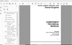
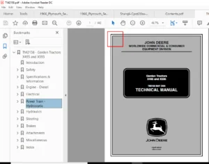
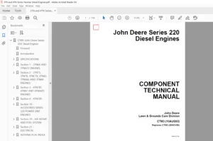
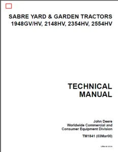
IMAGES PREVIEW OF THE MANUAL:
DESCRIPTION:
John Deere 245GLC Excavator Operation & Test Technical Manual TM12660 – PDF DOWNLOAD
- This manual is written for an experienced technician. Essential tools required in performing certain service work are identified in this manual and are recommended for use.
- Live with safety: Read the safety messages in the introduction of this manual and the cautions presented throughout the text of the manual.
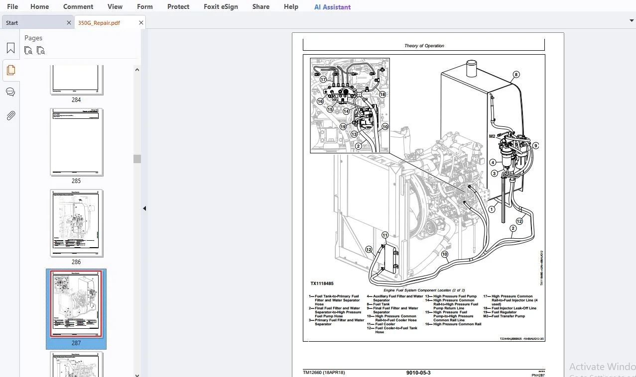
- Technical manuals are divided in two parts: repair and operation and tests. Repair sections tell how to repair the components. Operation and test sections help to quickly identify the majority of routine failures quickly.
- Information is organized in groups for the various components requiring service instruction. At the beginning of each group are summary listings of all applicable essential tools, service equipment and tools, other materials needed to do the job, service parts kits, specifications, wear tolerances, and torque values.
- Technical manuals are concise guides for specific machines. They are on-the-job guides containing only the vital information needed for diagnosis, analysis, testing, and repair.
- Fundamental service information is available from other sources covering basic theory of operation, fundamentals of troubleshooting, general maintenance, and basic type of failures and their causes.
TABLE OF CONTENTS:
John Deere 245GLC Excavator Operation & Test Technical Manual TM12660 – PDF DOWNLOAD
Contents...............................................................................................................................   5
	General Information................................................................................................................   7
		Safety.........................................................................................................................   9
			Recognize Safety Information...............................................................................................   9
			Follow Safety Instructions.................................................................................................   9
			Operate Only If Qualified..................................................................................................   9
			Wear Protective Equipment..................................................................................................  10
			Avoid Unauthorized Machine Modifications...................................................................................  10
			Control Pattern Selector—If Equipped.......................................................................................  11
			Add Cab Guarding for Special Uses..........................................................................................  11
			Inspect Machine............................................................................................................  11
			Stay Clear of Moving Parts.................................................................................................  11
			Avoid High-Pressure Fluids.................................................................................................  12
			Avoid High-Pressure Oils...................................................................................................  12
			Work In Ventilated Area....................................................................................................  13
			Prevent Fires..............................................................................................................  13
			Prevent Battery Explosions.................................................................................................  14
			Handle Chemical Products Safely............................................................................................  14
			Decommissioning — Proper Recycling and Disposal of Fluids and Components...................................................  15
			Exhaust Filter Ash Handling and Disposal...................................................................................  15
			Prepare for Emergencies....................................................................................................  15
			Clean Debris from Machine..................................................................................................  16
			Use Steps and Handholds Correctly..........................................................................................  16
			Start Only From Operator's Seat............................................................................................  16
			Use and Maintain Seat Belt.................................................................................................  16
			Prevent Unintended Machine Movement........................................................................................  17
			Avoid Work Site Hazards....................................................................................................  17
			Keep Riders Off Machine....................................................................................................  18
			Avoid Backover Accidents...................................................................................................  18
			Inspect and Maintain ROPS..................................................................................................  18
			Avoid Machine Tip Over.....................................................................................................  19
			Use Special Care When Lifting Objects......................................................................................  19
			Add and Operate Attachments Safely.........................................................................................  20
			Park and Prepare for Service Safely........................................................................................  21
			Service Cooling System Safely..............................................................................................  21
			Remove Paint Before Welding or Heating.....................................................................................  22
			Make Welding Repairs Safely................................................................................................  22
			Drive Metal Pins Safely....................................................................................................  22
			Clean Exhaust Filter Safely................................................................................................  23
	Diagnostics........................................................................................................................  33
		Main Controller (MCZ) Diagnostic Trouble Codes.................................................................................  35
			Main Controller (MCZ) Diagnostic Trouble Codes.............................................................................  35
			Controller Area Network 0 (CAN 0) Circuit Diagnostics......................................................................  35
			Controller Area Network 1 (CAN 1) Circuit Diagnostics......................................................................  35
			Interface Controller Area Network (N-CAN) Diagnostics......................................................................  35
			Engine Controller Area Network (Engine CAN) Diagnostics....................................................................  35
			011000.02 — Abnormal EEPROM................................................................................................  35
				Abnormal EEPROM Diagnostic Procedure...................................................................................  35
			011001.02 — Abnormal RAM...................................................................................................  36
				Abnormal RAM Diagnostic Procedure......................................................................................  36
			011002.02 — Abnormal A/D Converter.........................................................................................  37
				Abnormal A/D Converter Diagnostic Procedure............................................................................  37
			011003.03 — Abnormal Sensor Voltage........................................................................................  37
				Abnormal Sensor Voltage Diagnostic Procedure...........................................................................  37
			011006.02 — Engine Controller Communication Error..........................................................................  38
			011007.02 — (CAN 0) Data Converter Communication Error 1...................................................................  38
			011008.02 — (CAN 1) Data Converter Communication Error 2...................................................................  38
			011009.02 — (CAN 0) Monitor Controller Communication Error 1...............................................................  39
			011010.02 — (CAN 1) Monitor Controller Communication Error 2...............................................................  39
			011100.02 — Abnormal Engine Speed..........................................................................................  39
				Abnormal Engine Speed Diagnostic Procedure.............................................................................  39
			011101.03 — Engine Control Dial Sensor Circuit High Input..................................................................  39
				Engine Control Dial Sensor Circuit High Input Diagnostic Procedure.....................................................  40
			011101.04 — Engine Control Dial Sensor Circuit Low Input...................................................................  41
				Engine Control Dial Sensor Circuit Low Input Diagnostic Procedure......................................................  41
			011200.03 — Pump 1 Delivery Pressure Sensor Circuit High Input.............................................................  42
				Pump 1 Delivery Pressure Sensor Circuit High Diagnostics...............................................................  42
			011200.04 — Pump 1 Delivery Pressure Sensor Circuit Low Input..............................................................  44
				Pump 1 Delivery Pressure Sensor Circuit Low Input Diagnostic Procedure.................................................  44
			011202.03 — Pump 2 Delivery Pressure Sensor Circuit High Input.............................................................  46
				Pump 2 Delivery Pressure Sensor Circuit High Input Diagnostic Procedure................................................  46
			011202.04 — Pump 2 Delivery Pressure Sensor Circuit Low Input..............................................................  48
				Pump 2 Delivery Pressure Sensor Circuit Low Input Diagnostic Procedure.................................................  48
			011203.03 — Pump 3 Delivery Pressure Sensor Circuit High Input.............................................................  50
				Pump 3 Delivery Pressure Sensor Circuit High Input Diagnostic Procedure................................................  50
			011203.04 — Pump 3 Delivery Pressure Sensor Circuit Low Input..............................................................  51
				Pump 3 Delivery Pressure Sensor Circuit Low Input Diagnostic Procedure.................................................  51
			011206.03 — Pump 1 Flow Control Pressure Sensor Circuit High Input.........................................................  53
				Pump 1 Flow Control Pressure Sensor Circuit High Input Diagnostic Procedure............................................  53
			011206.04 — Pump 1 Flow Control Pressure Sensor Circuit Low Input..........................................................  54
				Pump 1 Flow Control Pressure Sensor Circuit Low Input Diagnostic Procedure.............................................  54
			011207.03 — Pump 3 Flow Control Pressure Sensor Circuit High Input.........................................................  56
				Pump 3 Flow Control Pressure Sensor Circuit High Input Diagnostic Procedure............................................  56
			011207.04 — Pump 3 Flow Control Pressure Sensor Circuit Low Input..........................................................  57
				Pump 3 Flow Control Pressure Sensor Circuit Low Input Diagnostic Procedure.............................................  57
			011208.03 — Pump 2 Flow Control Pressure Sensor Circuit High Input.........................................................  59
				Pump 2 Flow Control Pressure Sensor Circuit High Input Diagnostic Procedure............................................  59
			011208.04 — Pump 2 Flow Control Pressure Sensor Circuit Low Input..........................................................  60
				Pump 2 Flow Control Pressure Sensor Circuit Low Input Diagnostic Procedure.............................................  60
			011301.03 — Swing Pressure Sensor Circuit High Input.......................................................................  62
				Swing Pilot Pressure Sensor Circuit High Input Diagnostic Procedure....................................................  62
			011301.04 — Swing Pilot Pressure Sensor Circuit Low Input..................................................................  63
				Swing Pilot Pressure Sensor Circuit Low Input Diagnostic Procedure.....................................................  63
			011302.03 — Boom Up Pilot Pressure Sensor Circuit High Input...............................................................  64
				Boom Up Pilot Pressure Sensor Circuit High Input Diagnostic Procedure..................................................  64
			011302.04 — Boom Up Pilot Pressure Sensor Circuit Low Input................................................................  66
				Boom Up Pilot Pressure Sensor Circuit Low Input Diagnostic Procedure...................................................  66
			011303.03 — Arm In Pressure Sensor Circuit High Input......................................................................  67
				Arm In Pilot Pressure Sensor Circuit High Input Diagnostic Procedure...................................................  67
			011303.04 — Arm In Pressure Sensor Circuit Low Input.......................................................................  68
				Arm In Pilot Pressure Sensor Circuit Low Input Diagnostic Procedure....................................................  68
			011304.03 — Travel Pilot Pressure Sensor Circuit High Input................................................................  70
				Travel Pilot Pressure Sensor Circuit High Input Diagnostic Procedure...................................................  70
			011304.04 — Travel Pilot Pressure Sensor Circuit Low Input.................................................................  71
				Travel Pilot Pressure Sensor Circuit Low Input Diagnostic Procedure....................................................  71
			011307.03 — Front Attachment Pilot Pressure Sensor Circuit High Input......................................................  73
				Front Attachment Pilot Pressure Sensor Circuit High Input Diagnostic Procedure.........................................  73
			011307.04 — Front Attachment Pilot Pressure Sensor Circuit Low Input.......................................................  74
				Front Attachment Pilot Pressure Sensor Circuit Low Input Diagnostic Procedure..........................................  74
			011325.03 — Bucket Roll-In Pilot Pressure Sensor Circuit High Input........................................................  75
				Bucket Roll-In Pilot Pressure Sensor Circuit High Input Diagnostic Procedure...........................................  75
			011325.04 — Bucket Roll-In Pilot Pressure Sensor Circuit Low Input.........................................................  77
				Bucket Roll-In Pilot Pressure Sensor Circuit Low Input Diagnostic Procedure............................................  77
			011400.02 — Pump 2 Flow Rate Limit Solenoid Feedback Abnormal Feedback.....................................................  78
				Pump 2 Flow Rate Limit Solenoid Valve Abnormal Feedback Diagnostic Procedure...........................................  78
			011400.03 — Pump 2 Flow Rate Limit Solenoid Feedback High Current..........................................................  80
				Pump 2 Flow Rate Limit Solenoid Valve Feedback High Current Diagnostic Procedure.......................................  80
			011400.04 — Pump 2 Flow Rate Limit Solenoid Feedback Low Current...........................................................  81
				Pump 2 Flow Rate Limit Solenoid Valve Feedback Low Current Diagnostic Procedure........................................  81
			011401.02 — Pump 1 and 2 Torque P/S Valve Abnormal Feedback................................................................  83
				Pump 1 and 2 Torque P/S Valve Abnormal Feedback Diagnostic Procedure...................................................  83
			011401.03 — Pump 1 and 2 Torque P/S Valve Feedback High Current............................................................  85
				Pump 1 and 2 Torque P/S Valve Feedback High Current Diagnostic Procedure...............................................  85
			011401.04 — Pump 1 and 2 Torque P/S Valve Feedback Low Current.............................................................  86
				Pump 1 and 2 Torque P/S Valve Feedback Low Current Diagnostic Procedure................................................  86
			011402.02 — 5-Spool Solenoid Valve Unit (SF) Abnormal Feedback.............................................................  88
				5-Spool Solenoid Valve Unit (SF) Abnormal Feedback Diagnostic Procedure................................................  88
			011402.03 — 5-Spool Solenoid Valve Unit (SF) Feedback High Input...........................................................  90
				5-Spool Solenoid Valve Unit (SF) Feedback High Input Diagnostic Procedure..............................................  90
			011402.04 — 5-Spool Solenoid Valve Unit (SF) Feedback Low Input............................................................  91
				5-Spool Solenoid Valve Unit (SF) Feedback Low Input Diagnostic Procedure...............................................  91
			011403.02 — 5-Spool Solenoid Valve Unit (SC) Abnormal Feedback.............................................................  93
				5-Spool Solenoid Valve Unit (SC) Abnormal Feedback Diagnostic Procedure................................................  93
			011403.03 — 5-Spool Solenoid Valve Unit (SC) Feedback High Input...........................................................  95
				5-Spool Solenoid Valve Unit (SC) Feedback High Input Diagnostic Procedure..............................................  95
			011403.04 — 5-Spool Solenoid Valve Unit (SC) Feedback Low Input............................................................  96
				5-Spool Solenoid Valve Unit (SC) Feedback Low Input Diagnostic Procedure...............................................  96
			011406.02 — Pump 3 Torque P/S Valve Abnormal Feedback......................................................................  98
				Pump 3 Torque P/S Valve Abnormal Feedback Diagnostic Procedure.........................................................  98
			011406.03 — Pump 3 Torque P/S Valve Feedback High Current.................................................................. 100
				Pump 3 Torque P/S Valve Feedback High Current Diagnostic Procedure..................................................... 100
			011406.04 — Pump 3 Torque P/S Valve Feedback Low Current................................................................... 101
				Pump 3 Torque P/S Valve Feedback Low Current Diagnostic Procedure...................................................... 101
			011407.02 — 5-Spool Solenoid Valve Unit (SI) Abnormal Feedback............................................................. 103
				5-Spool Solenoid Valve Unit (SI) Abnormal Feedback Diagnostic Procedure................................................ 103
			011407.03 — 5-Spool Solenoid Valve Unit (SI) Feedback High Input........................................................... 105
				5-Spool Solenoid Valve Unit (SI) Feedback High Input Diagnostic Procedure.............................................. 105
			011407.04 — 5-Spool Solenoid Valve Unit (SI) Feedback Low Input............................................................ 106
				5-Spool Solenoid Valve Unit (SI) Feedback Low Input Diagnostic Procedure............................................... 106
			011408.02 — 2-Spool Solenoid Valve Unit (SJ) Abnormal Feedback............................................................. 108
				2-Spool Solenoid Valve Unit (SJ) Abnormal Feedback Diagnostic Procedure................................................ 108
			011408.03 — 2-Spool Solenoid Valve Unit (SJ) Feedback High Input........................................................... 110
				2-Spool Solenoid Valve Unit (SJ) Feedback High Input Diagnostic Procedure.............................................. 110
			011408.04 — 2-Spool Solenoid Valve Unit (SJ) Feedback Low Input............................................................ 111
				2-Spool Solenoid Valve Unit (SJ) Feedback Low Input Diagnostic Procedure............................................... 111
			011409.02 — 2-Spool Solenoid Valve Unit (SZ) Abnormal Feedback............................................................. 113
				2-Spool Solenoid Valve Unit (SZ) Abnormal Feedback Diagnostic Procedure................................................ 113
			011409.03 — 2-Spool Solenoid Valve Unit (SZ) Feedback High Input........................................................... 115
				2-Spool Solenoid Valve Unit (SZ) Feedback High Input Diagnostic Procedure.............................................. 115
			011409.04 — 2-Spool Solenoid Valve Unit (SZ) Feedback Low Input............................................................ 116
				2-Spool Solenoid Valve Unit (SZ) Feedback Low Input Diagnostic Procedure............................................... 116
			011427.02 — 5-Spool Solenoid Valve Unit (SE) Abnormal Feedback............................................................. 118
				5-Spool Solenoid Valve Unit (SE) Abnormal Feedback Diagnostic Procedure................................................ 118
			011427.03 — 5-Spool Solenoid Valve Unit (SE) Feedback High Current......................................................... 120
				5-Spool Solenoid Valve Unit (SE) Feedback High Current Diagnostic Procedure............................................ 120
			011427.04 — 5-Spool Solenoid Valve Unit (SE) Feedback Low Current.......................................................... 121
				5-Spool Solenoid Valve Unit (SE) Feedback Low Current Diagnostic Procedure............................................. 121
			011428.02 — 5-Spool Solenoid Valve Unit (SD) Abnormal Feedback............................................................. 122
				5-Spool Solenoid Valve Unit (SD) Abnormal Feedback Diagnostic Procedure................................................ 123
			011428.03 — 5-Spool Solenoid Valve Unit (SD) Feedback High Current......................................................... 124
				5-Spool Solenoid Valve Unit (SG) Feedback High Current Diagnostic Procedure............................................ 124
			011428.04 — 5-Spool Solenoid Valve Unit (SD) Feedback Low Current.......................................................... 125
				5-Spool Solenoid Valve Unit (SD) Feedback Low Current Diagnostic Procedure............................................. 125
			011434.02 — Attachment Relief 1 (Upper) Proportional Solenoid Valve Abnormal Feedback...................................... 127
				Attachment Relief 1 (Upper) Proportional Solenoid Valve Abnormal Feedback Diagnostic Procedure......................... 127
			011434.03 — Attachment Relief 1 (Upper) Proportional Solenoid Valve Feedback High Current.................................. 129
				Attachment Relief 1 (Upper) Proportional Solenoid Valve Feedback High Current Diagnostic Procedure..................... 129
			011434.04 — Attachment Relief 1 (Upper) Proportional Solenoid Valve Feedback Low Current................................... 130
				Attachment Relief 1 (Upper) Proportional Solenoid Valve Feedback Low Current Diagnostic Procedure...................... 130
			011435.02 — Attachment Relief 2 (Lower) Proportional Solenoid Valve Abnormal Feedback...................................... 132
				Attachment Relief 2 (Lower) Proportional Solenoid Valve Abnormal Feedback Diagnostic Procedure......................... 132
			011435.03 — Attachment Relief 2 (Lower) Proportional Solenoid Valve Feedback High Current.................................. 134
				Attachment Relief 2 (Lower) Proportional Solenoid Valve Feedback High Current Diagnostic Procedure..................... 134
			011435.04 — Attachment Relief 2 (Lower) Proportional Solenoid Valve Feedback Low Current................................... 135
				Attachment Relief 2 (Lower) Proportional Solenoid Valve Feedback Low Current Diagnostic Procedure...................... 135
			011436.02 — Breaker Relief Proportional Solenoid Valve Abnormal Feedback................................................... 137
				Breaker Relief Proportional Solenoid Valve Abnormal Feedback Diagnostic Procedure...................................... 137
			011436.03 — Breaker Relief Proportional Solenoid Valve Feedback High Current............................................... 139
				Breaker Relief Proportional Solenoid Valve Feedback High Current Diagnostic Procedure.................................. 139
			011436.04 — Breaker Relief Proportional Solenoid Valve Feedback Low Current................................................ 140
				Breaker Relief Proportional Solenoid Valve Feedback Low Current Diagnostic Procedure................................... 140
			011437.02 — 2-Spool Solenoid Valve Unit (A1) Abnormal Feedback............................................................. 141
				2-Spool Solenoid Valve Unit (A1) Abnormal Feedback Diagnostic Procedure................................................ 141
			011437.03 — 2-Spool Solenoid Valve Unit (A1) Feedback High Current......................................................... 143
				2-Spool Solenoid Valve Unit (A1) Feedback High Current Diagnostic Procedure............................................ 143
			011437.04 — 2-Spool Solenoid Valve Unit (A1) Feedback Low Current.......................................................... 144
				2-Spool Solenoid Valve Unit (A1) Feedback Low Current Diagnostic Procedure............................................. 144
			011438.02 — 2-Spool Solenoid Valve Unit (A2) Abnormal Feedback............................................................. 146
				2-Spool Solenoid Valve Unit (A2) Abnormal Feedback Diagnostic Procedure................................................ 146
			011438.03 — 2-Spool Solenoid Valve Unit (A2) Feedback High Current......................................................... 147
				2-Spool Solenoid Valve Unit (A2) Feedback High Current Diagnostic Procedure............................................ 147
			011438.04 — 2-Spool Solenoid Valve Unit (A2) Feedback Low Current.......................................................... 149
				2-Spool Solenoid Valve Unit (A2) Feedback Low Current Diagnostic Procedure............................................. 149
			011457.02 — 2-Speed Activation Solenoid Disconnected or Not Present........................................................ 150
				 2-Speed Activation Solenoid Disconnected or Not Present Diagnostic Procedure.......................................... 150
			011458.02 — (Auxiliary) Discontinuity of Selector Valve.................................................................... 152
				5-Spool Solenoid Valve Unit (SE) Abnormal Feedback Diagnostic Procedure................................................ 152
			011459.02 — Idle Stop Relay Circuit Malfunction............................................................................ 154
				Idle Stop Relay Circuit Malfunction Diagnostic Procedure............................................................... 154
			015011.03 —  Hydraulic Oil Temperature Sensor Circuit High Input (Pilot)................................................... 155
				Secondary Hydraulic Oil Temperature Sensor Circuit High Input Diagnostic Procedure..................................... 155
			015011.04 —  Hydraulic Oil Temperature Sensor Circuit Low Input (Pilot).................................................... 156
				Secondary Hydraulic Oil Temperature Sensor Circuit Low Input Diagnostic Procedure...................................... 156
			015016.03 — Right Analog Stroke Sensor Circuit High Input.................................................................. 158
				Auxiliary Function Lever (AFL) Proportional Control Switch Sensor Circuit High Input Diagnostic Procedure.............. 158
			015016.04 — Right Analog Stroke Sensor Circuit Low Input................................................................... 158
				Auxiliary Function Lever (AFL) Proportional Control Switch Sensor Circuit Low Input Diagnostic Procedure............... 159
			011810.03 — Electric Lever Operating Pressure Sensor 1 High Voltage........................................................ 160
				Auxiliary Function Lever (AFL) Solenoid Pressure Sensor (marked PS1) (B85) High Input Diagnostic Procedure............. 160
			011810.04 — Electric Lever Operating Pressure Sensor 1 Low Voltage......................................................... 161
				Auxiliary Function Lever (AFL) Solenoid Pressure Sensor (marked PS1) (B85) Low Input Diagnostic Procedure.............. 161
			011812.02 — OPT Electric Lever 1 Neutral Abnormal.......................................................................... 162
				OPT Electric Lever 1 Neutral Abnormal Diagnostic Procedure............................................................. 162
			011813.02 — OPT Electric Lever 1 Abnormal Operation........................................................................ 163
				OPT Electric Lever 1 Abnormal Operation Diagnostic Procedure........................................................... 163
			011816.02 — OPT Solenoid 1 Feedback Abnormal............................................................................... 165
				Auxiliary Function Lever (AFL) Solenoid A (marked 1A) (Y61) Abnormal Feedback Diagnostic Procedure..................... 165
			011816.03 — OPT Solenoid 1 Feedback Current High........................................................................... 167
				Auxiliary Function Lever (AFL) Solenoid A (marked 1A) (Y61) Feedback High Current Diagnostic Procedure................. 167
			011816.04 — OPT Solenoid 1 Feedback Current Low............................................................................ 169
				Auxiliary Function Lever (AFL) Solenoid A (marked 1A) (Y61) Feedback Low Current Diagnostic Procedure.................. 169
			011817.02 — OPT Solenoid 2 Feedback Abnormal............................................................................... 171
				Auxiliary Function Lever (AFL) Solenoid B (marked 1B) (Y62) Abnormal Feedback Diagnostic Procedure..................... 171
			011817.03 — OPT Solenoid 2 Feedback Current High........................................................................... 172
				Auxiliary Function Lever (AFL) Solenoid B (marked 1B) (Y62) Feedback High Current Diagnostic Procedure................. 173
			011817.04 — OPT Solenoid 2 Feedback Current Low............................................................................ 174
				Auxiliary Function Lever (AFL) Solenoid B (marked 1B) (Y62) Feedback Low Current Diagnostic Procedure.................. 174
			011901.03 — Hydraulic Oil Temperature Sensor Circuit High Input............................................................ 176
				Hydraulic Oil Temperature Sensor Circuit High Input Diagnostic Procedure............................................... 176
			011901.04 — Hydraulic Oil Temperature Sensor Circuit Low Input............................................................. 177
				Hydraulic Oil Temperature Sensor Circuit Low Input Diagnostic Procedure................................................ 177
			020010.02 — Abnormal Exhaust Filter........................................................................................ 178
				Abnormal Exhaust Filter Diagnostic Procedure........................................................................... 178
			020011.02 — Electric Lever Alarm........................................................................................... 178
				Electric Control Lever Alarm Diagnostic Procedure...................................................................... 179
			020012.02 — Line Filter Restriction Alarm.................................................................................. 179
			020303.02 — Electric Lever Pilot Cut Alarm................................................................................. 179
				Attachment Pedal or Blade and Outrigger Control Lever Alarm Diagnostic Procedure....................................... 179
		Engine Control Unit (ECU) Diagnostic Trouble Codes............................................................................. 181
			Engine Control Unit (ECU) Diagnostic Trouble Codes......................................................................... 181
			000081.00 — High Exhaust Filter Differential Pressure (P2453).............................................................. 181
			000081.01 — Low Exhaust Filter Differential Pressure (P2452)............................................................... 181
			000081.02 — Zero-Point Calibration of Exhaust Filter Differential Pressure Sensor is Abnormal (P2456)...................... 181
			000081.03 — Exhaust Filter Differential Pressure Sensor Circuit High Input (P2455)......................................... 181
			000081.04 — Exhaust Filter Differential Pressure Sensor Circuit Low Input (P2454).......................................... 181
			000091.02 — Accelerator Pedal Position Sensor 1-2 Correlation (P2138)...................................................... 181
			000091.03 — Accelerator Pedal Position Sensor 1 High Input (P2123)......................................................... 182
			000091.03 — Accelerator Pedal Position Sensor 2 High Input (P2128)......................................................... 182
			000091.04 — Accelerator Pedal Position Sensor 1 Low Input (P2122).......................................................... 182
			000091.04 — Accelerator Pedal Position Sensor 2 Low Input (P2127).......................................................... 182
			000100.03 — Engine Oil Pressure Sensor Circuit High Input (P0523).......................................................... 182
			000100.04 — Engine Oil Pressure Sensor Circuit Low Input (P0522)........................................................... 182
			000102.00 — Over Boost-Pressure (P0234).................................................................................... 182
			000102.03 — Boost Pressure Sensor Circuit High Input (P0238)............................................................... 183
			000102.04 — Boost Pressure Sensor Circuit Low Input (P0237)................................................................ 183
			000105.03 — Boost Temperature Sensor Circuit High Input (P1113)............................................................ 183
			000105.04 — Boost Temperature Sensor Circuit Low Input (P1112)............................................................. 183
			000108.03 — Atmospheric Pressure Sensor Circuit High Input (P2229)......................................................... 183
			000108.04 — Atmospheric Pressure Sensor Circuit Low Input (P2228).......................................................... 183
			000110.00 — Overheat (P0217)............................................................................................... 183
			000110.03 — Engine Coolant Temperature Circuit High Input (P0118).......................................................... 184
			000110.04 — Engine Coolant Temperature Circuit Low Input (P0117)........................................................... 184
			000132.03 — Air Flow Sensor Circuit High Input (P0103)..................................................................... 184
			000132.04 — Air Flow Sensor Circuit Low Input (P0102)...................................................................... 184
			000157.00 — Pressure Increase in Common Rail (Secondary) (P0088)........................................................... 184
			000157.03 — Common Rail Pressure Sensor Circuit High Input (P0193)......................................................... 184
			000157.04 — Common Rail Pressure Sensor Circuit Low Input (P0192).......................................................... 184
			000157.15 — Abnormal Common Rail Pressure (Over Pumping) (P0089)........................................................... 185
			000157.16 — Pressure Increase in Common Rail (Primary) (P0088)............................................................. 185
			000158.03 — Abnormally High Battery System Voltage (P0563)................................................................. 185
			000172.03 — Intake Air Temperature Sensor Circuit High Input (P0113)....................................................... 185
			000172.04 — Intake Air Temperature Sensor Circuit Low Input (P0112)........................................................ 185
			000173.00 — Abnormally High Exhaust Temperature Sensor 1 (DPF Inlet) (P0426)............................................... 185
			000173.03 — Exhaust Temperature Sensor 1 Circuit High Input (DPF Inlet) (P0428)............................................ 185
			000173.04 — Exhaust Temperature Sensor 1 Circuit Low Input (DPF Inlet) (P0427)............................................. 186
			000174.03 — Combustion Temperature Sensor Circuit High Input (P0183)....................................................... 186
			000174.04 — Combustion Temperature Sensor Circuit Low Input (P0182)........................................................ 186
			000190.00 — Engine Overrun (P0219)......................................................................................... 186
			000628.02 — Abnormal ROM (P0601)........................................................................................... 186
			000633.07 — Common Rail Pressure Limiter Open (P0087)...................................................................... 186
			000636.02 — Abnormal Cam Angle Sensor (No Signal) (P0340).................................................................. 186
			000636.07 — Phase Difference Between Cam and Sensor (P0016)................................................................ 187
			000639.02 — Abnormal CAN Time-Out (U0101).................................................................................. 187
			000639.19 — Abnormal CAN Bus (U0073)....................................................................................... 187
			000651.05 — Cylinder 1 Injector Circuit Open (P0201)....................................................................... 187
			000652.05 — Cylinder 2 Injector Circuit Open (P0202)....................................................................... 187
			000653.05 — Cylinder 3 Injector Circuit Open (P0203)....................................................................... 187
			000654.05 — Cylinder 4 Injector Circuit Open (P0204)....................................................................... 187
			000723.02 — Crank Position Sensor Failure (No Signal) (P0335).............................................................. 188
			000723.02 — Crank Position Sensor Failure (Abnormal Signal) (P0336)........................................................ 188
			001077.02 — Abnormal CPU (P0606)........................................................................................... 188
			001079.02 — Abnormal 5V-Electric Power Circuit #1 (P0641).................................................................. 188
			001080.02 — Abnormal 5V-Electric Power Circuit #2 (P0651).................................................................. 188
			001131.03 — Manifold Temperature Sensor Circuit High Input (P041C)......................................................... 188
			001131.04 — Manifold Temperature Sensor Circuit Low Input (P041D).......................................................... 188
			001239.01 — Pressure Decline in Common Rail (No Pumping Pressure) (P0093).................................................. 189
			001239.31 — Pressure Decline in Common Rail (No Pumping Pressure) (Fuel Temperature less than 5° C) (P0093)................ 189
			001239.17 — Pressure Decline in Common Rail (Lack of Pumping Pressure) (P1093)............................................. 189
			001239.31 — Pressure Decline in Common Rail (Lack of Pumping Pressure) (Fuel Temperature less than 5° C) (P1093)........... 189
			001347.03 — SCV Drive Circuit + Short Circuit B (P0092).................................................................... 189
			001347.04 — SCV Drive Circuit Open or Short Circuited to GND (P0091)....................................................... 189
			001381.03 — Fuel Filter Restriction Sensor Circuit High Input (P1294)...................................................... 190
			001381.04 — Fuel Filter Restriction Sensor Circuit Low Input (P1293)....................................................... 190
			001485.05 — Abnormal Main Relay Circuit (Inactivation) (P0685)............................................................. 190
			001485.06 — Abnormal Main Relay Circuit (Kept Closed) (P0687).............................................................. 190
			010001.02 — EGR Position Error (Brushless Type) (P0409).................................................................... 190
			010001.13 — Abnormal EGR Zero-Point Calibration (P1404).................................................................... 190
			010002.02 — Abnormal EGR Valve Control Circuit (P0404)..................................................................... 190
			010003.02 — Abnormal Injector Common 1 Circuit (P2146)..................................................................... 191
			010004.02 — Abnormal Injector Common 2 Circuit (P2149)..................................................................... 191
			010005.01 — Abnormal Charge Circuit (Bank 1) (P1261)....................................................................... 191
			010006.01 — Abnormal Charge Circuit (Bank 2) (P1262)....................................................................... 191
			010007.02 — Abnormal CPU Monitor IC (P0606)................................................................................ 191
			010008.02 — Abnormal A/D Converter (P060B)................................................................................. 191
			010009.02 — Abnormal 5V-Electric Power Circuit #3 (P0697).................................................................. 191
			010010.02 — Abnormal 5V-Electric Power Circuit #4 (P1655).................................................................. 192
			010012.02 — Abnormal 12V Circuit (P0560)................................................................................... 192
			010013.02 — Abnormal EEPROM/Abnormal HDEEPROM (P1621)...................................................................... 192
			010022.02 — Abnormal Intake Throttle Control Circuit (P0638)............................................................... 192
			010022.03 — Intake Throttle Position Sensor Circuit High Input (P0123)..................................................... 192
			010022.04 — Intake Throttle Position Sensor Circuit Low Input (P0122)...................................................... 192
			010023.02 — Abnormal CAN VNT Time-out/ISO-CAN VNT Communication Error (U0110).............................................. 192
			010023.12 — Abnormal VNT Turbo (P0045)..................................................................................... 193
			010023.19 — VNT Communication Error (U0411)................................................................................ 193
			010024.03 — Exhaust Temperature Sensor 2 Circuit High Input (DOC Inlet) (P042D)............................................ 193
			010024.04 — Exhaust Temperature Sensor 2 Circuit Low Input (DOC Inlet) (P042C)............................................. 193
			010025.05 — Exhaust Filter Light Failure (P1669)........................................................................... 193
			010026.00 — Exhaust Filter PM Over-Restriction 2 (P1455)................................................................... 193
			010026.15 — Exhaust Filter PM Over-Restriction (P242F)..................................................................... 193
			010027.00 — Exhaust Filter Cleaning Decision Error (P1471)................................................................. 194
			010028.00 — Abnormally High Exhaust Temperature Sensor 2 (DOC Outlet) (P042B).............................................. 194
			010029.00 — Over Frequent Exhaust Filter Regeneration Time-Out (P2458)..................................................... 194
			010032.02 — QR Code Error (P0602).......................................................................................... 194
			010033.02 — Abnormal RAM (P0604)........................................................................................... 194
			010040.19 — Abnormal ISO-CAN Bus (U0001)................................................................................... 194
		Monitor Controller (DSZ) Diagnostic Trouble Codes.............................................................................. 195
			Monitor Controller (DSZ) Diagnostic Trouble Codes.......................................................................... 195
			013002.02 — ECU Communication Error........................................................................................ 195
			013003.02 — Main Controller (MCZ) Communication Error 1.................................................................... 195
			013004.02 — Main Controller (MCZ) Communication Error 2.................................................................... 195
			013005.02 — Monitor Controller (DSZ) Communication Error 1................................................................. 195
			013006.02 — Monitor Controller (DSZ) Communication Error 2................................................................. 195
			013007.02 — Machine Controller (BCZ) Communication Error................................................................... 195
			020113.02 — System Error Alarm............................................................................................. 195
		Information Controller (ICZ) Diagnostic Trouble Codes.......................................................................... 197
			Information Controller (ICZ) Diagnostic Trouble Codes...................................................................... 197
			013303.02 — Abnormal Monitor Internal Temperature Sensor................................................................... 197
				Monitor Internal Temperature Sensor Diagnostic Procedure............................................................... 197
			013304.02 — Alternator Alarm............................................................................................... 197
				Alternator Alarm Diagnostic Procedure.................................................................................. 197
			013310.03 — Shorted Circuit in Coolant Temperature Sensor.................................................................. 198
				Shorted Circuit in Coolant Temperature Sensor Diagnostic Procedure..................................................... 198
			013311.03 — Fuel Level Sensor Open Circuit................................................................................. 198
				Fuel Level Sensor Open Circuit Diagnostic Procedure.................................................................... 199
			013311.04 — Fuel Level Sensor Shorted Circuit.............................................................................. 200
				Fuel Level Sensor Shorted Circuit Diagnostic Procedure................................................................. 200
			013334.02 — Radiator Coolant Error......................................................................................... 201
			014001.02 — Flash Memory Read/Write Error.................................................................................. 201
				Flash Memory Read/Write Error Diagnostic Procedure..................................................................... 201
			014002.02 — External RAM Read/Write Error.................................................................................. 202
				External RAM Read/Write Error Diagnostic Procedure..................................................................... 202
			014003.02 — Abnormal EEPROM................................................................................................ 202
				Abnormal EEPROM Diagnostics Procedure.................................................................................. 202
			014006.02 — Communication Terminal:Communication Error..................................................................... 202
				Communication Terminal:Communication Error Diagnostic Procedure........................................................ 202
			014008.02 — Abnormal Internal RAM.......................................................................................... 203
				Abnormal Internal RAM Diagnostic Procedure............................................................................. 203
			014021.02 — Communication Terminal Security Error.......................................................................... 203
			014022.02 — SIM Card Error................................................................................................. 204
			014023.02 — Security Error................................................................................................. 204
			020100.02 — Overheat Alarm................................................................................................. 204
			020101.02 — Engine Warning Alarm........................................................................................... 205
				Engine Warming Alarm Diagnostic Procedure.............................................................................. 205
			020102.02 — Engine Oil Pressure Alarm...................................................................................... 206
			020105.02 — Hydraulic Oil Filter Restriction Alarm......................................................................... 206
				Hydraulic Oil Filter Restriction Alarm Diagnostic Procedure............................................................ 206
			020106.02 — Air Cleaner Restriction Alarm.................................................................................. 207
				Air Cleaner Restriction Alarm Diagnostic Procedure..................................................................... 207
			020107.02 — Water Separator Alarm.......................................................................................... 208
				Water-in-Fuel Separator Alarm.......................................................................................... 208
			020109.02 — Pilot Control Shut-Off Lever Alarm............................................................................. 209
				Pilot Control Shut-Off Lever Alarm Diagnostic Procedure................................................................ 209
			020110.02 — Fuel Filter Restriction Alarm.................................................................................. 210
				Fuel Filter Restriction Alarm Diagnostic Procedure..................................................................... 210
			020114.02 — Overheat Alarm................................................................................................. 212
				Overheat Alarm......................................................................................................... 212
			020137.02 — Exhaust Filter Alarm........................................................................................... 213
			020141.02 — Exhaust Temperature Alarm...................................................................................... 213
			020142.02 — Intake Air Temperature Alarm................................................................................... 213
			020145.02 — Boost Temperature Increase Alarm............................................................................... 213
			020146.02 — Fuel Temperature Increase Alarm................................................................................ 213
			020149.02 — EGR Gas Temperature Alarm...................................................................................... 214
		Air Conditioner Controller (ACF) Diagnostic Trouble Codes...................................................................... 215
			Air Conditioner Controller (ACF) Diagnostic Trouble Codes.................................................................. 215
			11 — Open Circuit in Air Recirculation Sensor.............................................................................. 215
				Open Circuit in Air Recirculation Sensor Diagnostic Procedure.......................................................... 215
			12 — Short-Circuited Air Recirculation Sensor.............................................................................. 216
				Short-Circuited Air Recirculation Sensor Diagnostic Procedure.......................................................... 216
			13 — Open Circuit in Ambient Air Temperature Sensor........................................................................ 218
				Open Circuit in Ambient Air Temperature Sensor Diagnostics Procedure................................................... 218
			14 — Short-Circuited Ambient Air Temperature Sensor........................................................................ 219
				Short-Circuited Ambient Air Temperature Sensor Diagnostic Procedure.................................................... 219
			18 — Short-Circuited Solar Radiation Sensor................................................................................ 221
				Short-Circuited Solar Radiation Sensor Diagnostic Procedure............................................................ 221
			21 — Open Circuit in Air Conditioner Freeze Control Switch................................................................. 222
				Open Circuit in Air Conditioner Freeze Control Switch Diagnostic Procedure............................................. 222
			22 — Short-Circuited Air Conditioner Freeze Control Switch................................................................. 224
				Short-Circuited Air Conditioner Freeze Control Switch Diagnostic Procedure............................................. 224
			43 — Abnormal Air Conditioner and Heater Blower Port Change Servomotor..................................................... 225
				Abnormal Air Conditioner and Heater Blower Port Change Servomotor Diagnostic Procedure................................. 225
			44 — Abnormal Air Conditioner and Heater Mixer Servomotor.................................................................. 226
				Abnormal Air Conditioner and Heater Mixer Servomotor Diagnostic Procedure.............................................. 227
			51 — Abnormal High/Low Refrigerant Pressure................................................................................ 228
				Abnormal High/Low Refrigerant Pressure Diagnostic Procedure............................................................ 228
			91 — Communication Error................................................................................................... 229
			92 — CAN Bus Off Error..................................................................................................... 229
	Operational Checkout Procedure..................................................................................................... 231
		Operational Checkout Procedure................................................................................................. 233
			Operational Checkout....................................................................................................... 233
				Diagnostic Trouble Code Check.......................................................................................... 233
				Operational Checks—Key Switch Off, Engine Off Checks................................................................... 233
				Operational Checks—Key Switch On, Engine Off Checks.................................................................... 236
				Operational Checks—Key Switch On, Engine On Checks..................................................................... 248
	Engine............................................................................................................................. 283
		Theory of Operation............................................................................................................ 285
			Isuzu Engine............................................................................................................... 285
			Engine Fuel System Component Location...................................................................................... 286
			Engine Cooling System Component Location................................................................................... 288
			Cold Weather Starting Aid.................................................................................................. 289
			Engine Speed Control System Operation...................................................................................... 290
		Diagnostic Information......................................................................................................... 293
			Isuzu Engine............................................................................................................... 293
		Adjustments.................................................................................................................... 295
			Isuzu Engine............................................................................................................... 295
		Tests.......................................................................................................................... 297
			Isuzu Engine............................................................................................................... 297
	Electrical System.................................................................................................................. 301
		System Information............................................................................................................. 303
			Electrical Diagram Information............................................................................................. 303
		System Diagrams................................................................................................................ 311
			Explanation of Wire Markings............................................................................................... 311
			Fuse and Relay Specifications.............................................................................................. 312
			System Functional Schematic, Component Location, and Wiring Diagram Master Legend.......................................... 316
			System Functional Schematic................................................................................................ 323
			Cab Harness (W1) Component Location........................................................................................ 361
			Cab Harness (W1) Wiring Diagram............................................................................................ 365
			Machine Harness (W2) Component Location.................................................................................... 383
			Machine Harness (W2) Wiring Diagram........................................................................................ 387
			Monitor Harness (W3) Component Location.................................................................................... 400
			Monitor Harness (W3) Wiring Diagram........................................................................................ 402
			Engine Harness (W4) Component Location..................................................................................... 405
			Engine Harness (W4) Wiring Diagram......................................................................................... 413
			Side Camera Harness (W5) Component Location................................................................................ 416
			Side Camera Harness (W5) Wiring Diagram.................................................................................... 417
			Side Monitor Harness (W6) Component Location............................................................................... 418
			Side Monitor Harness (W6) Wiring Diagram................................................................................... 421
			Pump Harness (W8) Component Location....................................................................................... 424
			Pump Harness (W8) Wiring Diagram........................................................................................... 427
			Exhaust Filter Parked Cleaning Switch Harness (W9) Component Location...................................................... 429
			Exhaust Filter Parked Cleaning Switch Harness (W9) Wiring Diagram.......................................................... 429
			Pilot Shutoff Switch Harness (W11) Component Location...................................................................... 430
			Pilot Shutoff Switch Harness (W11) Wiring Diagram.......................................................................... 431
			Auxiliary Fuse Box Harness (W13) Component Location........................................................................ 434
			Auxiliary Fuse Box Harness (W13) Wiring Diagram............................................................................ 437
			Heated Air Seat Harness (W14) Component Location........................................................................... 440
			Heated Air Seat Harness (W14) Wiring Diagram............................................................................... 441
			Multi-Function Pilot Control Lever Harness (W15) Component Location........................................................ 442
			Multi-Function Pilot Control Lever Harness (W15) Wiring Diagram............................................................ 447
			Travel Alarm Cancel Switch Harness (W16) Component Location................................................................ 453
			Travel Alarm Cancel Switch Harness (W16) Wiring Diagram.................................................................... 453
			Attachment Harness (W17) Component Location................................................................................ 454
			Attachment Harness (W17) Wiring Diagram.................................................................................... 456
			Rear Camera Harness (W19) Component Location............................................................................... 458
			Rear Camera Harness (W19) Wiring Diagram................................................................................... 459
			9-Pin Service ADVISOR™ Connector (W20) Component Location.................................................................. 459
			9-Pin Service ADVISOR™ Connector (W20) Wiring Diagram...................................................................... 460
			Pilot Shutoff Valve Harness (W21) Component Location....................................................................... 461
			Pilot Shutoff Valve Harness (W21) Wiring Diagram........................................................................... 462
			Auxiliary 3-Button Cancel Switch Harness (W22) Component Location.......................................................... 462
			Auxiliary 3-Button Cancel Switch Harness (W22) Wiring Diagram.............................................................. 463
			Seat Heater Switch Harness (W24) Component Location........................................................................ 463
			Seat Heater Switch Harness (W24) Wiring Diagram............................................................................ 464
			Travel Alarm Harness (W26) Component Location.............................................................................. 465
			Travel Alarm Harness (W26) Wiring Diagram.................................................................................. 466
			Travel Sub Harness (W27) Component Location................................................................................ 466
			Travel Sub Harness (W27) Wiring Diagram.................................................................................... 467
			Starter Switch Harness (W29) Component Location............................................................................ 468
			Starter Switch Harness (W29) Wiring Diagram................................................................................ 468
			Data Converter Harness (W30) Component Location............................................................................ 470
			Data Converter Harness (W30) Wiring Diagram................................................................................ 472
			Data Converter Interface Harness (W31) Component Location.................................................................. 473
			Data Converter Interface Harness (W31) Wiring Diagram...................................................................... 474
			2-Speed Harness (W32) Component Location................................................................................... 475
			2-Speed Harness (W32) Wiring Diagram....................................................................................... 476
			Heater and Air Conditioner Harness (W41) Component Location................................................................ 477
			Heater and Air Conditioner Harness (W41) Wiring Diagram.................................................................... 479
			Spool Control Harness (W43) Component Location............................................................................. 481
			Spool Control Harness (W43) Wiring Diagram................................................................................. 482
			Auxiliary Solenoid Harness (W61) Component Location........................................................................ 484
			Auxiliary Solenoid Harness (W61) Wiring Diagram............................................................................ 486
			Auxiliary Function Lever (AFL) Harness (W75) Component Location............................................................ 488
			Auxiliary Function Lever (AFL) Harness (W75) Wiring Diagram................................................................ 491
			Auxiliary Function Lever (AFL) Solenoid Harness (W76) Component Location................................................... 493
			Auxiliary Function Lever (AFL) Solenoid Harness (W76) Wiring Diagram....................................................... 494
			Auxiliary Function Lever (AFL) Grip Harness (W77) Component Location....................................................... 495
			Auxiliary Function Lever (AFL) Grip Harness (W77) Wiring Diagram........................................................... 495
			Auxiliary Function Enable Switch Harness (W78) Component Location.......................................................... 495
			Auxiliary Function Enable Switch Harness (W78) Wiring Diagram.............................................................. 496
			Satellite (SAT) Harness (W6003) Component Location......................................................................... 496
			Satellite (SAT) Harness (W6003) Wiring Diagram............................................................................. 497
			JDLink™ Harness (W6004) Component Location................................................................................. 498
			JDLink™ Harness (W6004) Wiring Diagram..................................................................................... 501
		Sub-System Diagnostics......................................................................................................... 505
			Controller Area Network (CAN) Theory of Operation.......................................................................... 505
			Starting and Charging Circuit Theory of Operation.......................................................................... 509
			Monitor Controller (DSZ) Circuit Theory of Operation....................................................................... 515
			Engine Control Unit (ECU) Circuit Theory of Operation...................................................................... 523
			Exhaust Aftertreatment Circuit Theory of Operation......................................................................... 532
			Main Controller (MCZ) Circuit Theory of Operation.......................................................................... 535
			Travel Alarm Circuit Theory of Operation................................................................................... 550
			Machine Controller (BCZ) Circuit Theory of Operation....................................................................... 551
			Windshield Wiper and Washer Circuit Theory of Operation.................................................................... 553
			Lighting Circuit Theory of Operation....................................................................................... 557
			Pilot Shutoff Circuit Theory of Operation.................................................................................. 561
			Attachment Control Circuit Theory of Operation............................................................................. 564
		Monitor Operation.............................................................................................................. 573
			Service Menu............................................................................................................... 573
			Troubleshooting............................................................................................................ 573
			Monitoring................................................................................................................. 574
			Controller Version......................................................................................................... 578
			Issued Warning Record...................................................................................................... 579
			Operation.................................................................................................................. 579
			Side Monitor Operation..................................................................................................... 579
			Machine Setting............................................................................................................ 580
			Monitor Setting............................................................................................................ 585
			Alarm Setting.............................................................................................................. 587
			Engine Setting............................................................................................................. 587
			Exhaust Filter No.......................................................................................................... 587
		References..................................................................................................................... 589
			Reading Diagnostic Trouble Codes with Monitor Display...................................................................... 589
			Service ADVISOR™ Diagnostic Application.................................................................................... 589
			Service ADVISOR™ Connection Procedure...................................................................................... 590
			Reading Diagnostic Trouble Codes with Service ADVISOR™ Diagnostic Application.............................................. 591
			Clearing Engine Diagnostic Trouble Codes................................................................................... 593
			MPDr Application........................................................................................................... 598
			MPDr Connection Procedure.................................................................................................. 599
			Fuse Test.................................................................................................................. 600
			Relay Test................................................................................................................. 603
			Glow Plug Relay Test....................................................................................................... 603
			Pressure Sensor Test....................................................................................................... 604
			Solenoid Test.............................................................................................................. 605
			Proportional Solenoid Test................................................................................................. 606
			Temperature Sensor Test.................................................................................................... 607
			Alternator Test............................................................................................................ 608
			Controller Area Network (CAN) Circuit Test................................................................................. 611
				Controller Area Network (CAN) Diagnostics ............................................................................. 613
			Electrical Component Checks................................................................................................ 615
				Component Checks....................................................................................................... 615
			Battery Remove and Install................................................................................................. 621
			Rear Cover Remove and Install.............................................................................................. 624
			Main Controller (MCZ) Remove and Install................................................................................... 625
			Machine Controller (BCZ) Remove and Install................................................................................ 627
			Engine Control Unit (ECU) Remove and Install............................................................................... 628
			Exhaust Differential Pressure Sensor Zero Point Calibration................................................................ 630
			Ash Reset.................................................................................................................. 631
			No Load Max................................................................................................................ 632
			Data Converter Remove and Install.......................................................................................... 633
			Monitor Adjustable Relief Bleed Procedure.................................................................................. 634
			Monitor Controller (DSZ) Remove and Install................................................................................ 635
			Air Conditioner Controller (ACF) Remove and Install........................................................................ 635
			Key Switch Remove and Install.............................................................................................. 637
			Right Switch Console Remove and Install.................................................................................... 638
			Left Switch Console Remove and Install..................................................................................... 640
			Travel Alarm Remove and Install............................................................................................ 641
			Heater Control Disable and Enable.......................................................................................... 642
			Disconnect Tab Retainer Connectors......................................................................................... 642
			Disconnecting Spring Wire Clip Connectors.................................................................................. 642
			Replace DEUTSCH™ Connectors................................................................................................ 643
			Replace DEUTSCH™ Rectangular or Triangular Connectors...................................................................... 644
			Install DEUTSCH™ Contact................................................................................................... 645
			Replace WEATHER PACK™ Connector............................................................................................ 646
			Install WEATHER PACK™ Contact.............................................................................................. 647
			Replace (Pull Type) Metri-Pack™ Connectors................................................................................. 648
			Replace (Push Type) Metri-Pack™ Connectors................................................................................. 649
			Replace CINCH™ Connectors.................................................................................................. 649
			Install CINCH™ Contact..................................................................................................... 651
			Repair 32 and 48 Way CINCH™ Connectors..................................................................................... 652
			Remove Connector Body from Blade Terminals................................................................................. 654
	Power Train........................................................................................................................ 655
		Theory of Operation............................................................................................................ 657
			Track Adjuster and Recoil Spring Operation................................................................................. 657
			Travel Gear Case Operation................................................................................................. 658
		Diagnostic Information......................................................................................................... 661
			Noisy or Loose Track Chain................................................................................................. 661
				Noisy or Loose Track Chain Diagnostic Procedure........................................................................ 661
			Tight Track Chain.......................................................................................................... 661
				Tight Track Chain Diagnostic Procedure................................................................................. 661
			Frequent Track Chain Sag Adjustment Required............................................................................... 662
				Frequent Track Chain Sag Adjustment Required Diagnostic Procedure...................................................... 662
			Excessive Oil Leakage From Front Idler, Track Rollers, or Carrier Rollers.................................................. 662
				Excessive Oil Leakage From Front Idler, Track Rollers, or Carrier Rollers Diagnostic Procedure......................... 662
			Bent Track Shoes........................................................................................................... 662
				Bent Track Shoes Diagnostic Procedure.................................................................................. 662
			“Popping” of Track......................................................................................................... 663
				“Popping” of Track Diagnostic Procedure................................................................................ 663
			Cracked Track Link......................................................................................................... 663
				Cracked Track Link Diagnostic Procedure................................................................................ 663
			Chipped Link Rails......................................................................................................... 664
				Chipped Link Rails Diagnostic Procedure................................................................................ 664
			Individual Undercarriage Component Wear.................................................................................... 665
				Individual Undercarriage Component Wear Diagnostic Procedure........................................................... 665
			Measure Swing Bearing Wear................................................................................................. 666
	Hydraulic System................................................................................................................... 669
		Theory of Operation............................................................................................................ 671
			Hydraulic System Operation................................................................................................. 671
			Pilot System Operation..................................................................................................... 671
			Pilot Pump, Pressure Regulating Valve, and Filter Operation................................................................ 672
			Pilot Shutoff Solenoid Valve Operation..................................................................................... 673
			Pilot Control Valve Operation.............................................................................................. 676
			Travel Pilot Control Valve Operation....................................................................................... 678
			Pilot Operation of Control Valve Operation................................................................................. 681
			Pilot Signal Manifold Operation............................................................................................ 684
			Pump 1, Pump 2, Pump 3, and Drive Gear Case Operation...................................................................... 694
			Pump 1, Pump 2, and Pump 3 Regulator Operation............................................................................. 697
			Engine Speed Sensing Control Circuit Operation............................................................................. 703
			Control Valve Operation.................................................................................................... 705
			Control Valve Check Valves Identification and Operation.................................................................... 719
			Main Relief Valve Circuit Operation........................................................................................ 723
			Circuit Relief and Anticavitation Valve Operation.......................................................................... 727
			Travel Flow Combiner Valve Operation....................................................................................... 728
			Auxiliary Flow Combiner Valve and Bypass Shutoff Valve Operation........................................................... 732
			Boom Lower Meter-In Cut Valve Operation.................................................................................... 735
			Boom Regenerative Valve Circuit Operation.................................................................................. 737
			Dig Regenerative Valve Circuit Operation................................................................................... 739
			Arm Regenerative Valve Circuit Operation................................................................................... 745
			Bucket Regenerative Valve Circuit Operation................................................................................ 750
			Boom and Arm Reduced Leakage Valves Operation.............................................................................. 754
			Arm 1 Flow Rate Control Valve Circuit Operation............................................................................ 756
			Arm 2 Flow Rate Control Valve Circuit Operation............................................................................ 760
			Auxiliary Flow Rate Control Valve Circuit Operation........................................................................ 762
			Arm 3 and Boom 3 Spool Control Solenoid Valve Operation.................................................................... 765
			Swing Reduction Gear Case Operation........................................................................................ 768
			Swing Motor, Crossover Relief Valve, and Make-Up Check Valve Operation..................................................... 769
			Swing Motor Damper Valve................................................................................................... 772
			Swing Motor Park Brake Release Circuit Operation........................................................................... 780
			Center Joint Operation..................................................................................................... 781
			Travel Motor and Park Brake Valve Operation................................................................................ 782
			Travel Motor Speed Circuit Operation....................................................................................... 791
			Diesel Particulate Filter (DPF) Burn Solenoid Valves....................................................................... 795
			Cylinder Operation......................................................................................................... 798
			Return Filter Operation.................................................................................................... 799
			Auxiliary System Operation................................................................................................. 800
			Auxiliary Pilot Control Valve Operation.................................................................................... 800
			Flow Rate Select Solenoid Valve Operation.................................................................................. 810
			Flow Rate Pressure Reducing Valve Operation................................................................................ 811
			Secondary Auxiliary Relief Valve Solenoid Valve Operation.................................................................. 811
			Secondary Auxiliary Relief Control Valve Operation......................................................................... 812
			Secondary Auxiliary Relief Valve Operation................................................................................. 812
			Selector Valve Solenoid Valve Operation.................................................................................... 813
			Selector Valve Operation................................................................................................... 813
			Auxiliary Shuttle Valve Operation.......................................................................................... 814
			Auxiliary High Flow Line Kit Operation..................................................................................... 815
			Two Way Solenoid Kit Operation............................................................................................. 819
			Two Pump Combined Flow Kit Operation....................................................................................... 823
			Secondary Auxiliary Relief Kit Operation................................................................................... 829
			Low Flow Kit Operation..................................................................................................... 833
		Diagnostic Information......................................................................................................... 841
			All Hydraulic Functions Slow............................................................................................... 841
				All Hydraulic Functions Slow Diagnostic Procedure...................................................................... 841
			Hydraulic Oil Overheats.................................................................................................... 843
				Hydraulic Oil Overheats Diagnostic Procedure........................................................................... 843
			No Hydraulic Functions..................................................................................................... 845
				No Hydraulic Functions Diagnostic Procedure............................................................................ 845
			Poor Combined Operation.................................................................................................... 846
				Poor Combined Operation Diagnostic Procedure........................................................................... 846
			All Functions Cannot Be Operated........................................................................................... 847
				All Functions Cannot Be Operated Diagnostic Procedure.................................................................. 847
			Function Does Not Stop When Control Lever Released......................................................................... 848
				Function Does Not Stop When Control Lever Released Diagnostic Procedure................................................ 848
			Some Functions Cannot Be Operated, All Others Are Normal................................................................... 848
				Some Functions Cannot Be Operated, All Others Are Normal Diagnostic Procedure.......................................... 848
			All Functions Slow......................................................................................................... 849
				All Functions Slow Diagnostic Procedure................................................................................ 849
			Functions Move in Opposite Direction....................................................................................... 850
				Functions Move in Opposite Direction Diagnostic Procedure.............................................................. 850
			All Dig Functions Slow or No Power......................................................................................... 850
				All Dig Functions Slow or No Power..................................................................................... 851
			Some Dig Functions Slow (Not All).......................................................................................... 851
				Some Dig Functions Slow (Not All) Diagnostic Procedure................................................................. 851
			Load Drifts Down When Control Lever is in Neutral Position................................................................. 853
				Load Drifts Down When Control Lever is in Neutral Position Diagnostic Procedure........................................ 853
			Load Falls When Control Valve is Actuated to Raise Load With Engine Running at Slow Idle................................... 853
				Load Falls When Control Valve is Actuated to Raise Load With Engine Running at Slow Idle Diagnostic Procedure.......... 854
			H/P (High Power) Function Does Not Operate, PWR (Power) Mode is Normal..................................................... 854
				H/P (High Power) Function Does Not Operate, PWR (Power) Mode is Normal Diagnostic Procedure............................ 854
			Swing Speed Slow in Both Directions........................................................................................ 855
				Swing Speed Slow in Both Directions Diagnostic Procedure............................................................... 856
			Swing Speed Slow or Does Not Operate in One Direction...................................................................... 857
				Swing Speed Slow or Does Not Operate in One Direction Diagnostic Procedure............................................. 857
			Upperstructure Drift With Swing Valve in Neutral........................................................................... 858
				Upperstructure Drift With Swing Valve in Neutral Diagnostic Procedure.................................................. 858
			Swing Function Does Not Operate............................................................................................ 859
				Swing Function Does Not Operate Diagnostic Procedure................................................................... 859
			Travel Park Brakes Do Not Apply............................................................................................ 860
				Travel Park Brakes Do Not Apply Diagnostic Procedure................................................................... 860
			Track Will Not Move in One Direction....................................................................................... 861
				Track Will Not Move in One Direction Diagnostic Procedure.............................................................. 861
			Track Will Not Move in Either Direction.................................................................................... 862
				Track Will Not Move in Either Direction Diagnostic Procedure........................................................... 862
			Machine Mistracks at All Speeds in Both Directions......................................................................... 863
				Machine Mistracks at All Speeds in Both Directions Diagnostic Procedure................................................ 863
			Slow Travel Speed or Low Power............................................................................................. 865
				Slow Travel Speed or Low Power Diagnostic Procedure.................................................................... 865
			Combined Travel and Dig Functions Slow or No Power......................................................................... 866
				Combined Travel and Dig Functions Slow or No Power Diagnostic Procedure................................................ 866
			Travel is “Jerky”.......................................................................................................... 867
				Travel is “Jerky” Diagnostic Procedure................................................................................. 867
			Machine Will Not Hold Back and Park Brakes Engage and Disengage When Traveling Down an Incline............................. 868
				Machine Will Not Hold Back and Park Brakes Engage and Disengage When Traveling Down an Incline Diagnostic Procedure.... 868
			Machine Will Not Turn Smoothly in One Direction or Park Brake Grabs........................................................ 868
				Machine Will Not Turn Smoothly in One Direction or Park Brake Grabs Diagnostic Procedure............................... 868
			Pump 1, Pump 2, Pump 3, and Pilot Pump Line Identification................................................................. 869
			Control Valve Line Identification.......................................................................................... 870
			Swing Motor Line Identification............................................................................................ 873
			Pilot Control Valve-to-Pilot Signal Manifold Component Location—Excavator Pattern.......................................... 875
			Pilot Control Valve-to-Pilot Signal Manifold Component Location—Backhoe Pattern............................................ 879
			Pilot Signal Manifold-to-Control Valve Line Connection..................................................................... 882
			Travel System Component Location........................................................................................... 886
			Travel Hydraulic System Line Connection.................................................................................... 889
			Hydraulic System Schematic................................................................................................. 893
			Hydraulic System Component Location........................................................................................ 910
			Hydraulic System Line Connections.......................................................................................... 913
		Tests.......................................................................................................................... 917
			JT05800 Digital Thermometer Installation................................................................................... 917
			JT02156A Digital Pressure and Temperature Analyzer Kit Installation........................................................ 917
			General Hydraulic Oil Cleanup Procedure.................................................................................... 918
			Hydraulic Component Failure Cleanup Procedure.............................................................................. 920
			Hydraulic Oil Cleanup Procedure............................................................................................ 922
			Hydraulic Oil Tank Pressure Release Procedure.............................................................................. 923
			Hydraulic Oil Warm-Up Procedure............................................................................................ 924
			Pilot Pressure Regulating Valve Test and Adjustment........................................................................ 926
			Control Valve Spool Actuating Pilot Pressure Test.......................................................................... 928
			Dig Regenerative Solenoid Valve Test and Adjustment........................................................................ 930
			Arm Regenerative Solenoid Valve Test and Adjustment........................................................................ 932
			Power Dig Solenoid Valve Test and Adjustment............................................................................... 934
			Arm 2 Flow Control Solenoid Valve Test and Adjustment...................................................................... 936
			Torque Control Solenoid Valve Test and Adjustment.......................................................................... 938
			Arm 3 and Boom 3 Control Solenoid Valve Test and Adjustment................................................................ 941
			Pump Control Pilot Pressure Signal Test.................................................................................... 943
			Main Relief and Power Dig Valve Test and Adjustment........................................................................ 945
			Circuit Relief Valve Test and Adjustment................................................................................... 949
			Swing Motor Crossover Relief Valve Test and Adjustment..................................................................... 952
			Travel Motor Crossover Relief Valve Test and Adjustment.................................................................... 954
			Pump Regulator Test and Adjustment—Minimum Flow............................................................................ 957
			Pump Regulator Test and Adjustment—Maximum Flow............................................................................ 959
			Pump Flow Test............................................................................................................. 961
			Swing Motor Leakage Test................................................................................................... 968
			Travel Motor Leakage Test.................................................................................................. 969
			Cylinder Drift Test—Boom, Arm, and Bucket.................................................................................. 971
	Heating and Air Conditioning....................................................................................................... 973
		Theory of Operation............................................................................................................ 975
			Air Conditioning System Cycle of Operation................................................................................. 975
		Diagnostic Information......................................................................................................... 977
			Air Conditioning System Does Not Operate................................................................................... 977
				Air Conditioning System Does Not Operate Diagnostic Procedure.......................................................... 977
			No Air Flow From Heater and Air Conditioner Vents.......................................................................... 978
				No Air Flow From Heater and Air Conditioner Vents Diagnostic Procedure................................................. 978
			Air Conditioning Does Not Cool Interior of Cab............................................................................. 980
				Air Conditioning Does Not Cool Interior of Cab Diagnostic Procedure.................................................... 980
			Air Conditioning Runs Constantly, Too Cold................................................................................. 982
				Air Conditioning Runs Constantly, Too Cold Diagnostic Procedure........................................................ 982
			Interior Windows Continue to Fog Using Air Conditioner..................................................................... 983
				Interior Windows Continue to Fog Using Air Conditioner Diagnostics Procedure........................................... 983
			Heater System Does Not Operate............................................................................................. 983
				Heater System Does Not Operate Diagnostic Procedure.................................................................... 984
			Heater Does Not Warm Interior of Cab....................................................................................... 986
				Heater Does Not Warm Interior of Cab Diagnostic Procedure.............................................................. 986
			Interior Windows Continue to Fog Using Heater.............................................................................. 987
				Interior Windows Continue to Fog Using Heater Diagnostic Procedure..................................................... 987
			Heater and Air Conditioner Component Location.............................................................................. 989
		Tests.......................................................................................................................... 993
			Refrigerant Cautions and Proper Handling................................................................................... 993
			Heater and Air Conditioner Operational Checks.............................................................................. 993
				Visual Inspection of Components........................................................................................ 993
			Air Conditioner Compressor Clutch Test..................................................................................... 995
			Refrigerant Leak Test...................................................................................................... 995
			Refrigerant Hoses and Tubing Inspection.................................................................................... 995
			Air Conditioner Compressor Belt Check...................................................................................... 996
			Air Conditioner High/Low-Pressure Switch Test.............................................................................. 997
			Air Conditioner Freeze Control Switch Test................................................................................. 998
			R134a Air Conditioning System Test......................................................................................... 999
			Operating Pressure Diagnostic Chart........................................................................................1000
	Dealer Fabricated Tools............................................................................................................1001
		Dealer Fabricated Tools........................................................................................................1003
			DFT1218 Split Flange Hose Cap..............................................................................................1003
Page Number............................................................................................................................   5
	Section 9000.......................................................................................................................   7
		Group 01.......................................................................................................................   9
	Section 9001.......................................................................................................................  33
		Group 10.......................................................................................................................  35
		Group 20....................................................................................................................... 181
		Group 30....................................................................................................................... 195
		Group 40....................................................................................................................... 197
		Group 50....................................................................................................................... 215
	Section 9005....................................................................................................................... 231
		Group 10....................................................................................................................... 233
	Section 9010....................................................................................................................... 283
		Group 05....................................................................................................................... 285
		Group 15....................................................................................................................... 293
		Group 20....................................................................................................................... 295
		Group 25....................................................................................................................... 297
	Section 9015....................................................................................................................... 301
		Group 05....................................................................................................................... 303
		Group 10....................................................................................................................... 311
		Group 15....................................................................................................................... 505
		Group 16....................................................................................................................... 573
		Group 20....................................................................................................................... 589
	Section 9020....................................................................................................................... 655
		Group 05....................................................................................................................... 657
		Group 15....................................................................................................................... 661
	Section 9025....................................................................................................................... 669
		Group 05....................................................................................................................... 671
		Group 15....................................................................................................................... 841
		Group 25....................................................................................................................... 917
	Section 9031....................................................................................................................... 973
		Group 05....................................................................................................................... 975
		Group 15....................................................................................................................... 977
		Group 25....................................................................................................................... 993
	Section 9900.......................................................................................................................1001
		Group 99.......................................................................................................................1003
S.S 24/02/2025