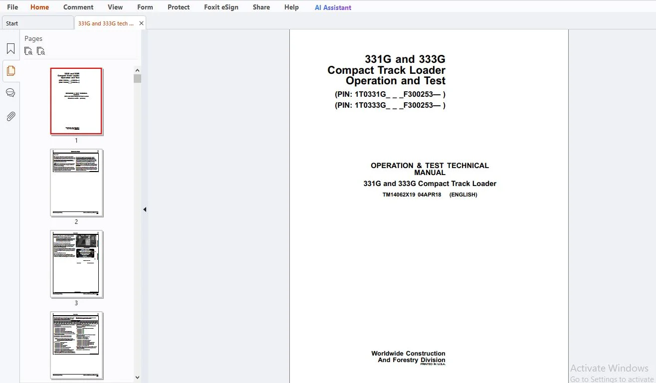
John Deere 331G & 333G Compact Track Loader Operation & Test Technical Manual TM14062X19 – PDF DOWNLOAD
$33.95
Instant English PDF of John Deere TM14062X19 Operation & Test for 331G and 333G CTLs (PIN F300253—). 824 pages covering DTCs, operational checkout, engine, electrical, hydro, hydraulics, HVAC and dealer tools.
Description
IMAGES PREVIEW OF THE MANUAL:
| Manual number | TM14062X19 |
| Type | Operation & Test Technical Manual (Repair TM sold separately) |
| Models / PIN | 331G 1T0331G___F300253— • 333G 1T0333G___F300253— |
| Publication | 04 April 2018 |
| Language | English |
| Pages | 824 |
| Downloadable / format | YES — instant PDF |
| File size | 28.28 MB |
This manual is written for an experienced technician. Essential tools required for certain service work are identified in the groups and are recommended for use. Live with safety: read the safety messages in the introduction and the cautions presented throughout the text before you connect Service ADVISOR™, crack a hydraulic fitting, or clear an exhaust-filter code.
John Deere technical manuals split into two families. Repair sections tell how to repair the components. Operation and Test sections — this file, TM14062X19 — help you identify the majority of routine failures quickly: codes, checkout, theory, diagrams, tests and adjustments. Information is organised in groups. At the beginning of each group you get summary listings of essential tools, service equipment, other materials, service-parts kits, specifications, wear tolerances and torque values. Technical manuals are concise on-the-job guides containing only the vital information needed for diagnosis, analysis, testing and repair.
Confirm the machine PIN before you buy. This TM covers 331G (1T0331G___F300253—) and 333G (1T0333G___F300253—). Earlier serials and the component Repair manual are different publications.
Why technicians keep TM14062X19 on the laptop
| Codes by controller, not a dump DCU, ECU, EMU, HCU, left and right joysticks, SSM, VCU and rear-camera display each have their own DTC chapter — DEF, throttle, park brake, boom/bucket solenoids, CAN and camera included. | Checkout before you guess Operational checkout runs DTC check plus switched-power-off / engine-off, switched-power-on / engine-off, and switched-power-on / engine-on tests so you do not skip a seat switch, lap bar or creep-mode input. | |
| Harness maps that match the machine W1 through W44 component locations and wiring diagrams — rear engine, cab, left/right main, JDLink™, radio, camera, Quik-Tatch™, DEF valve, pedals, joysticks and HVAC. | Hydro, hydraulics and HVAC tests Relief, charge, high-flow, drift, cylinder leakage, pump flow, fan motor, park-brake release, R134a charge and pressure chart — plus hydrostatic pump flow and mechanical/control neutral adjustments. |
Complete contents — TM14062X19
Section 9000 — General Information & Safety
Group 01 opens the book the John Deere way: recognize safety information, follow instructions, operate only if qualified. The safety list is not filler. It is the first thing a dealer tech is expected to live with on a compact track loader with high-pressure hydro, DEF aftertreatment and a pressurized cab door.
- Recognize safety information and follow safety instructions
- Operate only if qualified; wear protective equipment
- Avoid unauthorized machine modifications; inspect the machine
- Stay clear of moving parts
- Avoid high-pressure fluids and high-pressure oils
- Work in a ventilated area; avoid static-electricity risk when refueling
- Prevent fires; in case of machine fire
- Prevent battery explosions; handle chemical products safely; handle starting fluid safely
- Decommissioning — proper recycling and disposal of fluids and components
- Exhaust-filter ash handling and disposal; clean exhaust filter safely
- Prepare for emergencies; clean debris from machine
- Add cab guarding for special uses; use steps and handholds correctly
- Start only from the operator’s seat; use and maintain the seat belt
- Prevent unintended machine movement; avoid work-site hazards
- Keep riders off the machine; avoid backover accidents
- Avoid machine tip-over; operating on slopes; operating or traveling on public roads
- Inspect and maintain ROPS; travel safely
- Prevent acid burns; add and operate attachments safely
- Park and prepare for service safely; service the cooling system safely
- Remove paint before welding or heating; make welding repairs safely; drive metal pins safely
- Service tires safely; handle cab door safely if equipped
Section 9001 — Diagnostics (DTC library by controller)
This is the largest diagnostic block in the manual. Codes are grouped by the module that sets them, so you jump from a monitor display to the right chapter instead of scrolling a single unsorted list. Where the factory book includes a diagnostic procedure under a code, that procedure is in the PDF.
Group 05 — Dosing Control Unit (DCU) codes
DEF level, temperature, quality, dosing pump, tank heater and DCU supply. Includes full diagnostic procedures for heater-valve resistance, tank temperature high and insufficient tank heating.
- 001761.01 DEF Level Very Low · 001761.03 / .04 DEF Level Circuit Fault · 001761.13 DEF Level Calibration · 001761.15 DEF Level Slightly High · 001761.18 DEF Level Moderately Low
- 003031.00 DEF Temperature Very High · 003031.02 Invalid · 003031.03 / .04 Circuit Fault · 003031.13 Calibration · 003031.15 Slightly High · 003031.17 Slightly Low
- 003515.02 DEF Sensor Value Invalid · 003515.03 / .04 Circuit Fault · 003515.13 Calibration
- 003516.00 DEF Concentration Very High · 003516.01 Very Low · 003516.03 / .04 Circuit Fault · 003516.13 Calibration · 003521.13 DEF Fluid Calibration
- 004334.03 / .04 DEF Dosing Unit Pump Circuit Fault · 004334.15 Slightly High · 004334.17 Slightly Low
- 004366.05 Tank Heater Coolant Control Valve High Resistance (procedure) · 004366.06 Low Resistance (procedure) · 004366.16 Tank Temperature Moderately High (procedure) · 004366.18 Insufficient Heating (procedure)
- 005137.00 DEF Heating Valve Very High · 005137.04 / .05 Circuit Fault · 523555.03 / .04 Heating Valve Circuit Fault
- 523560.02 Main Relay Invalid · 523560.07 Main Relay Fault
- 523581.00 Temperature Sensor Very High · 523592.00 Heater Relay Very High · 523592.03 / .04 / .05 Heater Relay Circuit Fault
- 523594.03 DEF Tank Heater Circuit Fault · 523630.02 DEF Temperature Sensor Invalid
- 523634.09 / 523635.09 DEF Sensor Communication Fault · 523640.05 DCU Supply Voltage Circuit Fault
Group 10 — Engine Control Unit (ECU) codes
- 000028.00 / .01 / .03 / .04 Service Throttle Very High / Very Low / Circuit Fault
- 000029.00 / .01 / .02 / .03 / .04 / .08 / .15 Foot Throttle Very High / Very Low / Invalid / Circuit / Signal / Slightly High
- 000091.00 / .01 / .02 / .03 / .04 / .08 / .15 Hand Throttle Very High / Very Low / Invalid / Circuit / Signal / Slightly High
- 000100.01 Oil Pressure Very Low · 000100.04 Oil Pressure Circuit Fault
- 000158.00 / .01 System Voltage Very High / Very Low · 000167.01 / .04 / .05 System Voltage Very Low / Circuit Fault
- 000237.13 Vehicle ID Calibration · 000237.31 Vehicle ID Fault
- 001202.02 ECU Invalid · 001485.02 Main Relay Invalid · 001485.07 Main Relay Circuit Fault
- 522243.02 Start Aid Invalid · 522243.03 / .04 / .05 / .06 Start Aid Circuit Fault
- 522314.00 Coolant Temperature Very High · 522323.00 Engine Air Filter Restriction Very High
- 522596.09 / 522597.09 / 522599.09 / 522600.09 / 522601.09 / 522618.09 / 522619.09 ECU Communication Fault
- 522609.09 EGR Communication Fault · 522730.08 ECU Signal Fault · 522730.12 ECU Fault · 522994.04 ECU Circuit Fault · 523513.09 DCU Communication Fault
Group 20 — Engagement and Monitor Unit (EMU) codes
- 000096.03 / .04 Fuel Level Circuit Fault · 000158.00 / .01 System Voltage Very High / Very Low
- 000162.04 2-Speed Switch Circuit Fault · 000628.12 Programming Fault
- 000920.05 / .06 Alarm Output Circuit Fault · 001196.11 Antitheft Fault · 001504.04 Seat Switch Circuit Fault
- 002000.09 ECU Communication Fault · 002142.09 SSM Communication Fault · 002228.09 HCU Communication Fault · 002251.09 SAR Communication Fault
- 003413.04 Door Switch Circuit Fault · 521050.04 Aux Flow Switch Circuit Fault · 521197.04 Courtesy Light Switch Circuit Fault
- 522379.05 / .06 Park Brake Solenoid Circuit Fault
- 522826.00 / .04 Fan Purge Switch Very High / Circuit Fault · 522827.04 Fan Auto Switch Circuit Fault
- 522828.03 / .04 / .07 Creep Mode Switch Circuit Fault / Fault · 522859.04 Lap Bar Switch Circuit Fault
- 523217.06 Hyd Valve Power 3 · 523218.06 HST Valve Power · 523219.06 Hyd Valve Power 1
- 523693.03 / .04 Aux Hydraulic In 1 Circuit Fault · 523694.03 / .04 / .12 Aux Hydraulic In 2 Circuit Fault / Fault
- 523822.04 High Flow Switch Circuit Fault · 523935.05 / .06 Aux Hyd Extend Sol · 523941.05 / .06 Aux Hyd Retract Sol
- 523948.05 / .06 Ride Control Sol 1 · 523949.05 / .06 Ride Control Sol 2
- 524225.04 Remote Start In Circuit Fault · 524264.11 Checksum Fault
Group 30 — Hydraulic Control Unit (HCU) codes
- 000630.13 Calibration Memory Calibration
- 001594.00 / .01 / .02 / .14 Left Speed In Very High / Very Low / Invalid / Fault
- 001595.00 / .01 / .02 / .14 Right Speed In Very High / Very Low / Invalid / Fault
- 002201.09 Right Joystick Communication Fault · 002213.09 Left Joystick Communication Fault
- 002660.07 Right Joystick X Fault · 002661.07 Right Joystick Y Fault · 002697.07 Left Joystick X Fault · 002698.07 Left Joystick Y Fault
- 516193.03 / .04 / .07 / .16 / .18 Left Pedal In 1 Circuit / Fault / Moderately High / Moderately Low
- 516194.03 / .04 Left Pedal In 2 · 516195.03 / .04 Right Pedal In 2 · 516196.03 / .04 / .07 / .16 / .18 Right Pedal In 1
- 516197.06 Hyd Port Lock Sol Circuit Fault
- 520652.05 / .06 Bucket Curl Sol · 520653.05 / .06 Bucket Dump Sol · 520882.13 Loader Threshold Calibration
- 522377.03 / .04 / .12 / .13 Boom Position In 1 Circuit / Fault / Calibration · 522378.03 / .04 Boom Position In 2
- 522436.03 / .04 / .12 / .13 Bucket Position In 1 Circuit / Fault / Calibration · 522437.03 / .04 Bucket Position In 2
- 522447.05 / .06 Right Pump Fwd Sol · 522448.05 / .06 Right Pump Rev Sol · 522449.05 / .06 Left Pump Rev Sol · 522450.05 / .06 Left Pump Fwd Sol
- 522507.13 Loader Angle Calibration · 523108.13 Transmission Calibration
- 523217.03 / .04 Hyd Valve Power 3 · 523218.03 / .04 HST Valve Power · 523219.03 / .04 Hyd Valve Power 1
- 523411.05 / .06 / .16 Boom Down Sol Circuit / Moderately High · 523414.05 / .06 / .16 Boom Up Sol Circuit / Moderately High
Group 40 — Left Joystick Controller (JSL) codes
- 002697.03 / .04 / .13 / .14 Left Joystick X Circuit Fault / Calibration / Fault
- 002698.03 / .04 / .13 / .14 Left Joystick Y Circuit Fault / Calibration / Fault
Group 50 — Right Joystick Controller (JSR) codes
- 002660.03 / .04 / .13 / .14 Right Joystick X Circuit Fault / Calibration / Fault
- 002661.03 / .04 / .13 / .14 Right Joystick Y Circuit Fault / Calibration / Fault
Group 60 — Sealed Switch Module (SSM) codes
- 000629.12 Control Unit Fault · 002033.09 VCU Communication Fault
- 002634.04 / .05 Ignition Relay Circuit Fault · 003997.04 / .05 Wake Up Output Circuit Fault
- SSM Buttons 1 through 15 — each with Circuit Fault and Communication Fault (523850 through 523868 family)
Group 70 — Vehicle Control Unit (VCU) codes
- 000100.03 Oil Pressure Circuit Fault · 000158.03 / .04 System Voltage Circuit Fault · 000168.03 / .04 Battery Voltage Circuit Fault · 000628.12 Programming Fault
- 000977.05 / .06 Fan Direction Sol · 001071.05 / .06 Fan Speed Sol
- 001508.00 / .03 / .04 Hydraulic Oil Temp Very High / Circuit Fault · 001713.00 / .03 Hyd Filter Switch Very High / Circuit Fault
- 003512.03 / .04 Sensor Supply 4 · 003597.03 / .04 Sensor Supply 1 · 003598.03 / .04 Sensor Supply 2 · 516249.04 Sensor Supply 1
- 004056.05 / .06 2-Speed Output Circuit Fault
- 520194.13 / .14 Vehicle ID Calibration / Fault · 520714.05 / .06 Self Level Circuit Fault
- 520849.03 / .04 Right JS Trigger Circuit Fault · 521466.05 / .06 Fan Direction Sol · 521806.05 / .06 HST Bypass Sol
- 522329.00 Water In Fuel Very High · 522820.05 / .06 High Flow Sol Circuit Fault
- 524084.00 / .03 / .04 HST Oil Temp Very High / Circuit Fault · 524264.11 Checksum Error
Group 80 — Rear Camera Display (VC1) codes
- 000629.12 Control Unit Fault · 520760.02 Camera Signal Invalid
- 516628.10 / 516629.10 / 516630.10 / 521857.10 / 521858.10 / 521859.10 Monitor Button Fault
Section 9005 — Operational Checkout Procedure
Group 10 is the first live-machine path after codes. Run it in order so a dead seat switch or an open switched-power circuit is caught before you condemn a pump.
- Diagnostic Trouble Code Check
- Operational checks — Switched Power OFF, Engine OFF
- Operational checks — Switched Power ON, Engine OFF
- Operational checks — Switched Power ON, Engine ON
Section 9010 — Engine
- Theory: John Deere engine, exhaust aftertreatment, cold-start operation
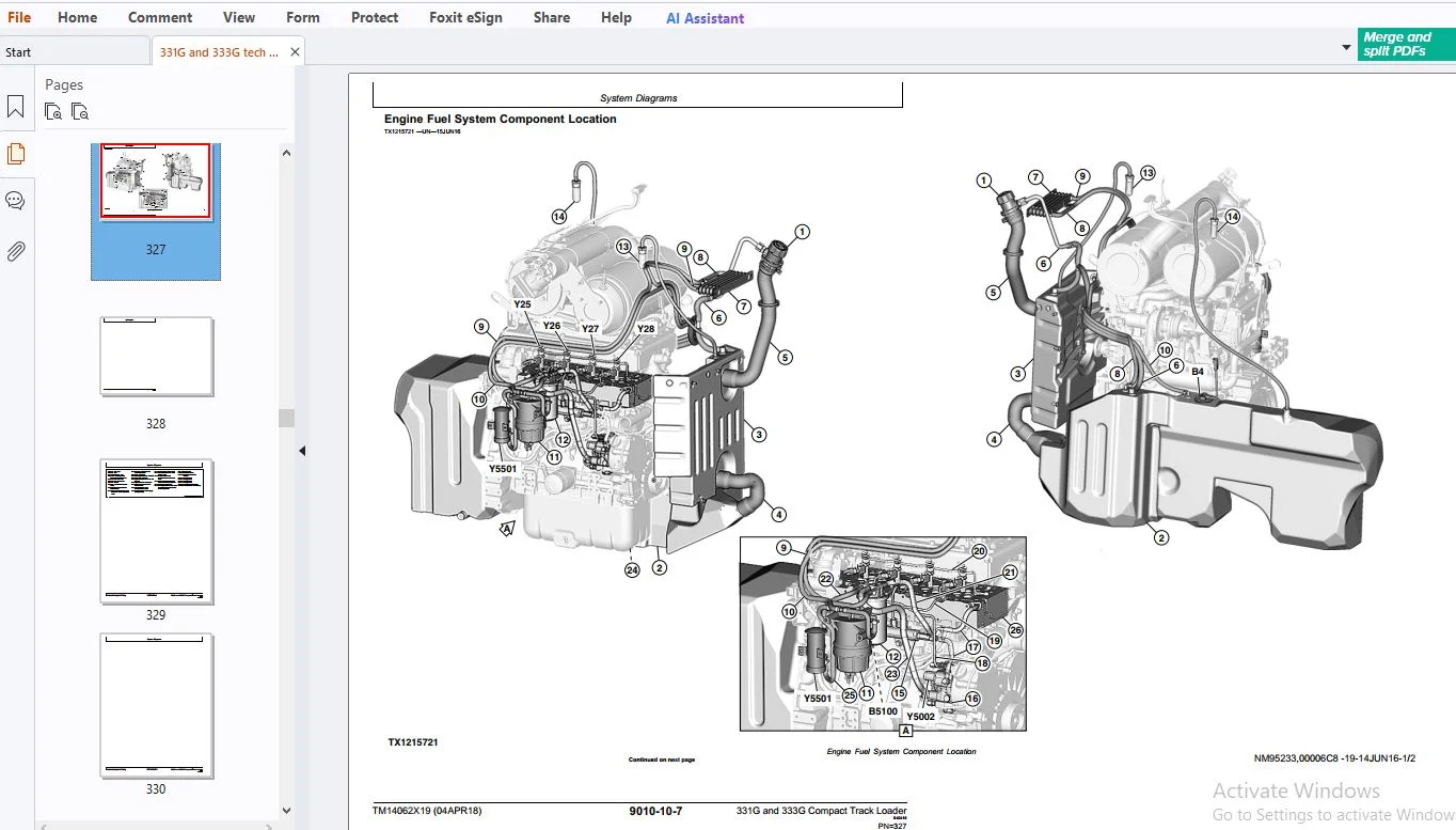
- System diagrams: engine overview, cooling-system component location, fuel-system component location, intake and exhaust component location
- Diagnostic information: engine hard to start or does not start when cold, with diagnostic procedure
- Adjustments: service filter cleaning
- Tests: fluid sampling procedure if equipped
Section 9015 — Electrical System
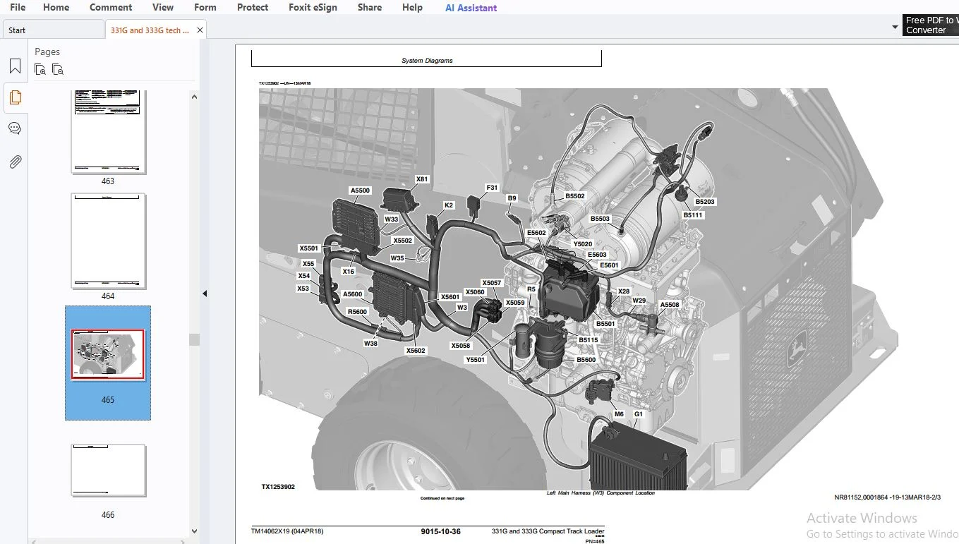
This is the electrical half of the O&T book: theory for every major circuit, then the master schematic and every harness W1–W44, then Service ADVISOR™ / JDLink™ / DTC reading, monitor service-mode screens, the diagnostic test box, calibrations and component tests.
Theory of operation
- Starting circuit · Controller Area Network (CAN) · Rear camera circuit
- Engine Control Unit (ECU) circuit · Exhaust aftertreatment circuit · Engagement and Monitor Unit (EMU) circuit
- Lighting circuit · Hydraulic system control circuit · Backup alarm circuit
- Quik-Tatch™ circuit if equipped · JDLink™ circuit
- Hydrostatic system control circuit · Hydraulic fan control circuit
System diagrams and harnesses
- Electrical diagram information, schematic symbols, fuse and relay specifications
- System functional schematic, component location and wiring-diagram master legend
- W1 Rear Engine harness — location and diagram
- W2 Cab harness — location and diagram
- W3 Left Main harness — location and diagram
- W4 Right Main harness — location and diagram
- W5 Dual Flasher harness · W7 JDLink™ harness · W8 Radio harness · W10 Rear Camera harness
- W11 Attachment Control Frame · W12 Attachment Control Boom
- W17 Heater and Air Conditioner · W19 Creep Mode Speed Switch
- W20 Engine Interface · W21 Engine · W22 Engine Fuel System
- W23 Pedal Interface · W25 Joystick Jumper
- W29 Diesel Exhaust Fluid (DEF) Control Valve
- W40 Quik-Tatch™ Frame · W42 Quik-Tatch™ Boom · W44 Quik-Tatch™ Actuator
Diagnostic information, monitor, test box, adjustments and tests
- Service ADVISOR™ connection · JDLink™ connection · reading DTCs · intermittent DTC diagnostics
- Monitor service mode: exhaust-filter service cleaning, set auto clean, shift mode, codes
- Diagnostics screens — switches, sensors, left joystick, right joystick, speeds, VCU / EMU / ECU outputs and power, controller info, cal values
- Antitheft master code, calibration, owner controls, anti-theft configure / enable / operate if equipped
- EMU display messages and EMU operation
- Diagnostic test box setup and functional test; two-wire and three-wire sensor circuit checks (out of range high and low)
- Hydrostatic system calibration · boom and bucket calibration · auxiliary hydraulics calibration · manual tracking adjustment · EH foot-pedal calibration
- Electrical component checks and specifications · solenoid test and observable-symptom check · alternator test · CAN circuit test and CAN diagnostics
Section 9020 — Power Train
- Power-train system operation and component location
- Loose track — diagnostic procedure
- Tight track — diagnostic procedure
- Frequent track-tension adjustment required — diagnostic procedure
- Excessive oil leakage from idlers and rollers — diagnostic procedure
- “Popping” of track — diagnostic procedure
- Individual undercarriage component wear — diagnostic procedure
- Check and adjust track tension
Section 9025 — Hydraulic System
Theory covers the base hydraulic system plus the options that show up on 331G / 333G spec sheets: high-flow pump, self-leveling valve and ride control. Symptom trees then send you to a named diagnostic procedure instead of a generic “check pressure.”
- Theory: hydraulic system operation, hydraulic oil filter manifold, high-flow pump if equipped, self-leveling valve if equipped, ride control if equipped, hydraulic pump, hydraulic fan, hydraulic control valve
- Diagrams: hydraulic system schematic and component location
- Symptoms with procedures: no hydraulic functions; boom will not raise; boom will not lower; bucket will not dump; bucket will not curl; bucket will not self-level when boom is raised; bucket dumps during self-leveling cycle; boom drifts down; boom drifts up; bucket drifts down; bucket drifts up; hydraulic functions slow or no power; functions “jerky” or “spongy”; hydraulic system noise; hydraulic oil overheats; hydraulic fan malfunctions; hydraulic fan will not reverse
- Adjustment: ride-control accumulator gas-charge procedure if equipped
- Tests: JT05800 digital thermometer install; JT02156A digital pressure and temperature analyzer install; remote start box install; hydraulic system pressure release; port-lock solenoid and spool test; system relief; charge-pressure relief; high-flow relief; circuit relief; function drift; cylinder leakage; hydraulic pump flow; charge-pump flow; fan-motor speed; fan-motor case drain; auxiliary coupler manifold leakage
Section 9026 — Hydrostatic System
- Theory: hydrostatic system operation, hydrostatic pump, charge pump, two-speed hydrostatic motor, hydrostatic control valve, park-brake system
- Diagrams: hydrostatic schematic and component location
- Symptoms with procedures: machine does not move in either direction; hydrostatic pump or motor noise; slow response to speed changes; low power; tracks powered on one side not the other; will not shift into or out of high speed; mistracking; park brakes do not hold; park brakes do not release; grinding noise while operating
- Tests: engine speed control for testing; multi-function valve pressure-relief test; hydrostatic pump flow test; hydrostatic pump mechanical-neutral adjustment; hydrostatic pump control-neutral adjustment; track speed test; park-brake release-pressure test
Section 9031 — Heating and Air Conditioning
- A/C system cycle of operation and HVAC component location
- A/C does not operate · A/C does not cool cab · A/C runs constantly / too cold
- Heating system does not operate · heating does not warm cab · interior windows continue to fog
- R134a cautions and handling, oil-charge capacity, refrigerant-charge capacity
- Heater and A/C operational checks and visual inspection
- Compressor clutch test, refrigerant leak test, hose and tubing inspection
- High/low-pressure switch test, freeze-control switch test, system test, operating-pressure diagnostic chart
Section 9900 — Dealer Fabricated Tools
- DFT1318 Motor Speed Sensor Test Harness
- DFT1325 Solenoid Power Harness
Factory section map (for techs who navigate by group)
9000 Group 01 Safety · 9001 Groups 05–80 DTC libraries · 9005 Group 10 Operational checkout · 9010 Groups 05–25 Engine · 9015 Groups 05–25 Electrical · 9020 Groups 05–20 Power train · 9025 Groups 05–25 Hydraulics · 9026 Groups 05–25 Hydrostatic · 9031 Groups 05–25 HVAC · 9900 Group 99 Dealer tools.
Who this download is for
- Dealer and independent techs running Service ADVISOR™ on a 331G or 333G after PIN F300253
- Shops chasing DEF / DCU codes, EH joystick or pedal faults, boom/bucket drift, high-flow or ride-control issues
- Field techs who need harness W-numbers, fuse/relay specs and CAN theory in the cab
- Owners who want the factory operational-checkout path before authorizing a pump or motor
- Anyone who already owns the Repair TM and needs the matching Operation & Test companion
Live with safety — high-pressure hydro, DEF and aftertreatment ash are in this book for a reason
Read the introduction safety messages and the cautions in the text before you test. Avoid high-pressure fluids. Support the boom. Isolate switched power when the checkout says so. Handle DEF, exhaust-filter ash and R134a as the manual specifies. This listing is a digital copy of TM14062X19 Operation & Test for 331G / 333G compact track loaders. Always follow current John Deere practice and local regulations.
Download TM14062X19 now
Add to cart, check out, and receive the English PDF immediately — 824 pages / 28.28 MB of operation, diagnostics and test procedures for the John Deere 331G and 333G compact track loader. Search a DTC, print a harness sheet, run the checkout. No courier wait.
Search terms: John Deere 331G operation and test manual PDF, John Deere 333G TM14062X19, 331G 333G compact track loader DTC list, John Deere CTL hydraulic test procedures, 333G wiring diagram W1 W2 W3 W4, 331G hydrostatic pump flow test, John Deere G-series skid steer track loader Service ADVISOR codes, Quik-Tatch DEF DCU HCU VCU SSM manual.