Trusted Business
Verified & Licensed
Virus Free Files
100% Safe Downloads
Secure Payment
SSL Protected
Instant Delivery
Available Immediately
John Deere 350GLC Excavator Operation & Test Manual TM13206X19 – PDF DOWNLOAD
$35.95
John Deere 350GLC Excavator Operation & Test Manual TM13206X19 – PDF DOWNLOAD
Instant PDF Download
Available immediately
Save to Your Device
Download & keep forever
Antivirus Scanned
100% virus-free
Trusted Worldwide
175,000+ customers
Description
John Deere 350GLC Excavator Operation & Test Manual TM13206X19 – PDF DOWNLOAD
FILE DETAILS:
John Deere 350GLC Excavator Operation & Test Manual TM13206X19 – PDF DOWNLOAD
Language : English
Pages : 1112
Downloadable : Yes
File Type : PDF
IMAGES PREVIEW OF THE MANUAL:
DESCRIPTION:
John Deere 350GLC Excavator Operation & Test Manual TM13206X19 – PDF DOWNLOAD
- This manual is written for an experienced technician. Essential tools required in performing certain service work are identified in this manual and are recommended for use.
- Live with safety: Read the safety messages in the introduction of this manual and the cautions presented throughout the text of the manual.
- Technical manuals are divided in two parts: repair and operation and tests. Repair sections tell how to repair the components. Operation and test sections help to quickly identify the majority of routine failures quickly.
- Information is organized in groups for the various components requiring service instruction. At the beginning of each group are summary listings of all applicable essential tools, service equipment and tools, other materials needed to do the job, service parts kits, specifications, wear tolerances, and torque values.
- Technical manuals are concise guides for specific machines. They are on-the-job guides containing only the vital information needed for diagnosis, analysis, testing, and repair.
- Fundamental service information is available from other sources covering basic theory of operation, fundamentals of troubleshooting, general maintenance, and basic type of failures and their causes.
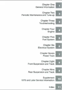
TABLE OF CONTENTS:
John Deere 350GLC Excavator Operation & Test Manual TM13206X19 – PDF DOWNLOAD
Contents......................................................................................................................   7
	General Information.......................................................................................................   9
		Safety................................................................................................................  11
			Recognize Safety Information......................................................................................  11
			Follow Safety Instructions........................................................................................  11
			Operate Only If Qualified.........................................................................................  11
			Wear Protective Equipment.........................................................................................  12
			Avoid Unauthorized Machine Modifications..........................................................................  12
			Control Pattern Selector—If Equipped..............................................................................  12
			Add Cab Guarding for Special Uses.................................................................................  12
			Inspect Machine...................................................................................................  13
			Stay Clear of Moving Parts........................................................................................  13
			Avoid High-Pressure Fluids........................................................................................  13
			Avoid High-Pressure Oils..........................................................................................  14
			Work In Ventilated Area...........................................................................................  14
			Avoid Static Electricity Risk When Refueling......................................................................  15
			Prevent Fires.....................................................................................................  15
			In Case of Machine Fire...........................................................................................  16
			Prevent Battery Explosions........................................................................................  16
			Handle Chemical Products Safely...................................................................................  16
			Decommissioning — Proper Recycling and Disposal of Fluids and Components..........................................  17
			Exhaust Filter Ash Handling and Disposal..........................................................................  17
			Prepare for Emergencies...........................................................................................  17
			Clean Debris from Machine.........................................................................................  18
			Use Steps and Handholds Correctly.................................................................................  18
			Start Only From Operator's Seat...................................................................................  18
			Use and Maintain Seat Belt........................................................................................  18
			Prevent Unintended Machine Movement...............................................................................  19
			Avoid Work Site Hazards...........................................................................................  19
			Keep Riders Off Machine...........................................................................................  20
			Avoid Backover Accidents..........................................................................................  20
			Inspect and Maintain ROPS.........................................................................................  20
			Avoid Machine Tip Over............................................................................................  21
			Use Special Care When Lifting Objects.............................................................................  21
			Travel Safely.....................................................................................................  22
			Add and Operate Attachments Safely................................................................................  22
			Park and Prepare for Service Safely...............................................................................  22
			Service Cooling System Safely.....................................................................................  23
			Remove Paint Before Welding or Heating............................................................................  23
			Make Welding Repairs Safely.......................................................................................  23
			Drive Metal Pins Safely...........................................................................................  24
			Clean Exhaust Filter Safely.......................................................................................  25
	Diagnostics...............................................................................................................  32
		Main Controller (MCZ) Diagnostic Trouble Codes........................................................................  33
			Main Controller (MCZ) Diagnostic Trouble Codes....................................................................  33
			Controller Area Network 0 (CAN 0) Circuit Diagnostics.............................................................  33
				Controller Area Network (CAN 0) Diagnostics...................................................................  33
			Controller Area Network 1 (CAN 1) Circuit Diagnostics.............................................................  41
				Controller Area Network (CAN 1) Diagnostic Procedure .........................................................  41
			Interface Controller Area Network (N-CAN) Diagnostics.............................................................  52
				Interface Controller Area Network (N-CAN) Diagnostics ........................................................  52
			Engine Controller Area Network (Engine CAN) Diagnostics ..........................................................  58
				Engine Controller Area Network (Engine CAN) Diagnostics ......................................................  59
			Aftertreatment Controller Area Network (AT CAN) Diagnostics.......................................................  63
				Aftertreatment Controller Area Network (AT CAN) Diagnostics...................................................  63
			011000.02 — Abnormal EEPROM.......................................................................................  68
				Abnormal EEPROM Diagnostic Procedure..........................................................................  68
			011001.02 — Abnormal RAM..........................................................................................  69
				Abnormal RAM Diagnostic Procedure.............................................................................  69
			011002.02 — Abnormal A/D Converter................................................................................  69
				Abnormal A/D Converter Diagnostic Procedure...................................................................  69
			011003.03 — Abnormal Sensor Voltage...............................................................................  70
				Abnormal Sensor Voltage Diagnostic Procedure..................................................................  70
			011006.02 — Engine Controller Communication Error.................................................................  71
			011007.02 — (CAN 0) Data Converter Communication Error 1..........................................................  71
			011008.02 — (CAN 1) Data Converter Communication Error 2..........................................................  71
			011009.02 — (CAN 0) Monitor Controller Communication Error 1......................................................  71
			011010.02 — (CAN 1) Monitor Controller Communication Error 2......................................................  72
			011100.02 — Abnormal Engine Speed.................................................................................  72
				Abnormal Engine Speed Diagnostic Procedure....................................................................  72
			011101.03 — Engine Speed Dial Sensor Circuit High Input...........................................................  72
				Engine Speed Dial Sensor Circuit High Input Diagnostic Procedure..............................................  72
			011101.04 — Engine Speed Dial Sensor Circuit Low Input............................................................  74
				Engine Speed Dial Sensor Circuit Low Input Diagnostic Procedure...............................................  74
			011200.03 — Pump 1 Delivery Pressure Sensor Circuit High Input....................................................  75
				Pump 1 Delivery Pressure Sensor Circuit High Diagnostics......................................................  75
			011200.04 — Pump 1 Delivery Pressure Sensor Circuit Low Input.....................................................  77
				Pump 1 Delivery Pressure Sensor Circuit Low Input Diagnostic Procedure........................................  77
			011202.03 — Pump 2 Delivery Pressure Sensor Circuit High Input....................................................  79
				Pump 2 Delivery Pressure Sensor Circuit High Input Diagnostic Procedure.......................................  79
			011202.04 — Pump 2 Delivery Pressure Sensor Circuit Low Input.....................................................  81
				Pump 2 Delivery Pressure Sensor Circuit Low Input Diagnostic Procedure........................................  81
			011206.03 — Pump 1 Flow Control Pressure Sensor Circuit High Input................................................  83
				Pump 1 Flow Control Pressure Sensor Circuit High Input Diagnostic Procedure...................................  83
			011206.04 — Pump 1 Flow Control Pressure Sensor Circuit Low Input.................................................  84
				Pump 1 Flow Control Pressure Sensor Circuit Low Input Diagnostic Procedure....................................  84
			011208.03 — Pump 2 Flow Control Pressure Sensor Circuit High Input................................................  86
				Pump 2 Flow Control Pressure Sensor Circuit High Input Diagnostic Procedure...................................  86
			011208.04 — Pump 2 Flow Control Pressure Sensor Circuit Low Input.................................................  87
				Pump 2 Flow Control Pressure Sensor Circuit Low Input Diagnostic Procedure....................................  87
			011301.03 — Swing Pressure Sensor Circuit High Input..............................................................  89
				Swing Pilot Pressure Sensor Circuit High Input Diagnostic Procedure...........................................  89
			011301.04 — Swing Pilot Pressure Sensor Circuit Low Input.........................................................  90
				Swing Pilot Pressure Sensor Circuit Low Input Diagnostic Procedure............................................  90
			011302.03 — Boom Up Pilot Pressure Sensor Circuit High Input......................................................  92
				Boom Up Pilot Pressure Sensor Circuit High Input Diagnostic Procedure.........................................  92
			011302.04 — Boom Up Pilot Pressure Sensor Circuit Low Input.......................................................  93
				Boom Up Pilot Pressure Sensor Circuit Low Input Diagnostic Procedure..........................................  93
			011303.03 — Arm In Pressure Sensor Circuit High Input.............................................................  94
				Arm In Pilot Pressure Sensor Circuit High Input Diagnostic Procedure..........................................  95
			011303.04 — Arm In Pressure Sensor Circuit Low Input..............................................................  96
				Arm In Pilot Pressure Sensor Circuit Low Input Diagnostic Procedure...........................................  96
			011304.03 — Travel Pilot Pressure Sensor Circuit High Input.......................................................  97
				Travel Pilot Pressure Sensor Circuit High Input Diagnostic Procedure..........................................  97
			011304.04 — Travel Pilot Pressure Sensor Circuit Low Input........................................................  99
				Travel Pilot Pressure Sensor Circuit Low Input Diagnostic Procedure...........................................  99
			011307.03 — Front Attachment Pilot Pressure Sensor Circuit High Input............................................. 100
				Front Attachment Pilot Pressure Sensor Circuit High Input Diagnostic Procedure................................ 100
			011307.04 — Front Attachment Pilot Pressure Sensor Circuit Low Input.............................................. 102
				Front Attachment Pilot Pressure Sensor Circuit Low Input Diagnostic Procedure................................. 102
			011400.02 — Pump 2 Flow Rate Limit Solenoid Valve Feedback Abnormal............................................... 103
				Pump 2 Flow Rate Limit Solenoid Valve Feedback Abnormal Diagnostic Procedure.................................. 103
			011400.03 — Pump 2 Flow Rate Limit Solenoid Valve Feedback High Current........................................... 105
				Pump 2 Flow Rate Limit Solenoid Valve Feedback High Current Diagnostic Procedure.............................. 105
			011400.04 — Pump 2 Flow Rate Limit Solenoid Valve Feedback Low Current............................................ 107
				Pump 2 Flow Rate Limit Solenoid Valve Feedback Low Current Diagnostic Procedure............................... 107
			011401.02 — Torque Control Solenoid Valve Abnormal Feedback....................................................... 108
				Torque Control Solenoid Valve Abnormal Feedback Diagnostic Procedure.......................................... 108
			011401.03 — Torque Control Solenoid Valve Feedback High Current................................................... 110
				Torque Control Solenoid Valve Feedback High Current Diagnostic Procedure...................................... 110
			011401.04 — Torque Control Solenoid Valve Feedback Low Current.................................................... 112
				Torque Control Solenoid Valve Feedback Low Current Diagnostic Procedure....................................... 112
			011402.02 — Dig Regenerative Solenoid Valve Feedback Current Abnormal............................................. 113
				Dig Regenerative Solenoid Valve Feedback Current Abnormal Diagnostic Procedure................................ 113
			011402.03 — Dig Regenerative Solenoid Valve Feedback Current High................................................. 115
				Dig Regenerative Solenoid Valve Feedback Current High Diagnostic Procedure.................................... 115
			011402.04 — Dig Regenerative Solenoid Valve Feedback Current Low.................................................. 117
				Dig Regenerative Solenoid Valve Feedback Current Low Diagnostic Procedure..................................... 117
			011403.02 — Arm Regenerative Solenoid Valve Feedback Current Abnormal............................................. 118
				Arm Regenerative Solenoid Valve Feedback Current Abnormal Diagnostic Procedure................................ 118
			011403.03 — Arm Regenerative Solenoid Valve Feedback Current High................................................. 120
				Arm Regenerative Solenoid Valve Feedback Current High Diagnostic Procedure.................................... 120
			011403.04 — Arm Regenerative Solenoid Valve Feedback Current Low.................................................. 122
				Arm Regenerative Solenoid Valve Feedback Current Low Diagnostic Procedure..................................... 122
			011404.02 — Power Dig Solenoid Feedback Current Abnormal.......................................................... 123
			011404.03 — Power Dig Solenoid Feedback Current High.............................................................. 123
			011404.04 — Power Dig Solenoid Feedback Current Low............................................................... 123
			011405.02 — Travel Speed Solenoid Feedback Current Abnormal....................................................... 124
			011405.03 — Travel Speed Solenoid Feedback Current High........................................................... 124
			011405.04 — Travel Speed Solenoid Feedback Current Low............................................................ 124
			011407.02 — Power Dig/Travel Speed Solenoid Valve Feedback Current Abnormal....................................... 124
				Power Dig/Travel Speed Solenoid Valve Feedback Current Abnormal Diagnostic Procedure.......................... 124
			011407.03 — Power Dig/Travel Speed Solenoid Valve Feedback Current High........................................... 126
				Power Dig/Travel Speed Solenoid Valve Feedback Current High Diagnostic Procedure.............................. 126
			011407.04 — Power Dig/Travel Speed Solenoid Valve Feedback Current Low............................................ 127
				Power Dig/Travel Speed Solenoid Valve Feedback Current Low Diagnostic Procedure............................... 127
			011457.02 — 2-Speed Activation Solenoid Valve Disconnected........................................................ 129
				2-Speed Activation Solenoid Valve Disconnected Diagnostic Procedure........................................... 129
			011458.02 — Selector Valve Solenoid Valve Disconnected............................................................ 131
				Selector Valve Solenoid Valve Disconnected Diagnostic Procedure............................................... 131
			011459.02 — Idle Stop Relay Circuit Malfunction................................................................... 133
				Idle Stop Relay Circuit Malfunction Diagnostic Procedure...................................................... 133
			015011.03 —  Hydraulic Oil Temperature Sensor Circuit High Input (Pilot).......................................... 134
				Secondary Hydraulic Oil Temperature Sensor Circuit High Input Diagnostic Procedure............................ 134
			015011.04 —  Hydraulic Oil Temperature Sensor Circuit Low Input (Pilot)........................................... 135
				Secondary Hydraulic Oil Temperature Sensor Circuit Low Input Diagnostic Procedure............................. 135
			015016.03 — Right Analog Stroke Sensor Circuit High Input......................................................... 136
				Auxiliary Function Lever (AFL) Proportional Control Switch Sensor Circuit High Input Diagnostic Procedure..... 136
			015016.04 — Right Analog Stroke Sensor Circuit Low Input.......................................................... 137
				Auxiliary Function Lever (AFL) Proportional Control Switch Sensor Circuit Low Input Diagnostic Procedure...... 137
			011810.03 — Electric Lever Operating Pressure Sensor 1 High Voltage............................................... 138
				Auxiliary Function Lever (AFL) Solenoid Pressure Sensor (marked PS1) (B85) High Input Diagnostic Procedure.... 138
			011810.04 — Electric Lever Operating Pressure Sensor 1 Low Voltage................................................ 140
				Auxiliary Function Lever (AFL) Solenoid Pressure Sensor (marked PS1) (B85) Low Input Diagnostic Procedure..... 140
			011812.02 — OPT Electric Lever 1 Neutral Abnormal................................................................. 141
				OPT Electric Lever 1 Neutral Abnormal Diagnostic Procedure.................................................... 141
			011813.02 — OPT Electric Lever 1 Abnormal Operation............................................................... 142
				OPT Electric Lever 1 Abnormal Operation Diagnostic Procedure.................................................. 142
			011816.02 — OPT Solenoid 1 Feedback Abnormal...................................................................... 144
				Auxiliary Function Lever (AFL) Solenoid A (marked 1A) (Y61) Abnormal Feedback Diagnostic Procedure............ 144
			011816.03 — OPT Solenoid 1 Feedback Current High.................................................................. 146
				Auxiliary Function Lever (AFL) Solenoid A (marked 1A) (Y61) Feedback High Current Diagnostic Procedure........ 146
			011816.04 — OPT Solenoid 1 Feedback Current Low................................................................... 147
				Auxiliary Function Lever (AFL) Solenoid A (marked 1A) (Y61) Feedback Low Current Diagnostic Procedure......... 147
			011817.02 — OPT Solenoid 2 Feedback Abnormal...................................................................... 149
				Auxiliary Function Lever (AFL) Solenoid B (marked 1B) (Y62) Abnormal Feedback Diagnostic Procedure............ 149
			011817.03 — OPT Solenoid 2 Feedback Current High.................................................................. 151
				Auxiliary Function Lever (AFL) Solenoid B (marked 1B) (Y62) Feedback High Current Diagnostic Procedure........ 151
			011817.04 — OPT Solenoid 2 Feedback Current Low................................................................... 152
				Auxiliary Function Lever (AFL) Solenoid B (marked 1B) (Y62) Feedback Low Current Diagnostic Procedure......... 152
			011901.03 — Hydraulic Oil Temperature Sensor Circuit High Input................................................... 154
				Hydraulic Oil Temperature Sensor Circuit High Input Diagnostic Procedure...................................... 154
			011901.04 — Hydraulic Oil Temperature Sensor Circuit Low Input.................................................... 155
				Hydraulic Oil Temperature Sensor Circuit Low Input Diagnostic Procedure....................................... 155
			020010.02 — Abnormal Exhaust Filter............................................................................... 156
				Abnormal Exhaust Filter Diagnostic Procedure.................................................................. 157
			020011.02 — Electric Lever Alarm.................................................................................. 157
				Electric Control Lever Alarm Diagnostic Procedure............................................................. 157
			020303.02 — Electric Lever Pilot Cut Alarm........................................................................ 157
				Attachment Pedal or Blade and Outrigger Control Lever Alarm Diagnostic Procedure.............................. 157
		Engine Control Unit (ECU) Diagnostic Trouble Codes.................................................................... 159
			Engine Control Unit (ECU) Diagnostic Trouble Codes................................................................ 159
			000111.07 — Coolant Level Low—Moderately Severe Level............................................................. 159
				Coolant Level Low—Moderately Severe Level Diagnostic Procedure................................................ 159
			000647.05 — Variable Speed Fan Solenoid Open Circuit.............................................................. 160
				Variable Speed Fan Solenoid Open Circuit Diagnostic Procedure................................................. 160
			000647.06 — Variable Speed Fan Solenoid High Current.............................................................. 161
				Variable Speed Fan Solenoid High Current Diagnostic Procedure................................................. 161
			000647.16 — Reversing Fan Switch Active Too Long.................................................................. 162
				Reversing Fan Switch Active Too Long Diagnostic Procedure..................................................... 162
			001639.00 — Fan Speed High—Moderately Severe Level................................................................ 163
				Fan Speed High—Moderately Severe Level Diagnostic Procedure................................................... 163
			001639.01 — Fan Speed Low—Most Severe Level....................................................................... 165
				Fan Speed Low—Most Severe Level Diagnostic Procedure.......................................................... 165
			001639.18 — Fan Speed Low—Moderately Severe Level................................................................. 166
			001761.01 — Diesel Exhaust Fluid Extremely Low.................................................................... 166
			001761.18 — Diesel Exhaust Fluid Very Low......................................................................... 167
			002030.09 — (CAN 0) Flex Power Controller Communication Error..................................................... 167
			002228.09 — (CAN 0) Main Controller (MCZ) Communication Error..................................................... 167
			003031.12 — Diesel Exhaust Fluid Temperature Sensor Fault......................................................... 167
			003353.31 — Alternator Excitation Fault........................................................................... 167
				Alternator Excitation Fault Diagnostic Procedure.............................................................. 168
			003516.01 — Diesel Exhaust Fluid Concentration Extremely Low...................................................... 169
			003516.07 — Diesel Exhaust Fluid Concentration Invalid............................................................ 169
			003516.09 — Diesel Exhaust Fluid Tank Header Communication Fault.................................................. 170
			003516.12 — Diesel Exhaust Fluid Concentration Sensor Fault....................................................... 170
			003517.12 — Diesel Exhaust Fluid Tank Level Sensor Fault.......................................................... 170
			003587.05 — Cold Start Aid Solenoid Open.......................................................................... 171
				Cold Start Aid Solenoid Open Diagnostic Procedure............................................................. 171
			003587.06 — Cold Start Aid Solenoid Short......................................................................... 172
				Cold Start Aid Solenoid Short Diagnostic Procedure............................................................ 172
			003701.14 — Exhaust Filter Cleaning Not Required.................................................................. 172
			003719.15 — Calculated Soot Level Slightly High................................................................... 172
			005484.05 — Reversing Fan Solenoid Open Circuit................................................................... 173
				Reversing Fan Solenoid Open Circuit Diagnostic Procedure...................................................... 173
			005484.06 — Reversing Fan Solenoid Short Circuit.................................................................. 173
				Reversing Fan Solenoid Short Circuit Diagnostic Procedure..................................................... 174
			520956.06 — Battery Disconnect Indicator Light Short to Ground.................................................... 174
				Battery Disconnect Indicator Light Short to Ground Diagnostic Procedure....................................... 174
		Monitor Controller (DSZ) Diagnostic Trouble Codes..................................................................... 177
			Monitor Controller (DSZ) Diagnostic Trouble Codes................................................................. 177
			013000.02 — Flash Memory Failure 1................................................................................ 177
				Flash Memory Failure 1 Diagnostic Procedure................................................................... 177
			013001.02 — Flash Memory Failure 2................................................................................ 177
				Flash Memory Failure 2 Diagnostic Procedure................................................................... 177
			013002.02 — ECU Communication Error............................................................................... 177
			013003.02 — Main Controller (MCZ) Communication Error 1........................................................... 178
			013004.02 — Main Controller (MCZ) Communication Error 2........................................................... 178
			013005.02 — Monitor Controller (DSZ) Communication Error 1........................................................ 178
			013006.02 — Monitor Controller (DSZ) Communication Error 2........................................................ 178
			013007.02 — Machine Controller (BCZ) Communication Error.......................................................... 178
			013334.02 — Radiator Coolant Error................................................................................ 178
			020113.02 — System Error Alarm.................................................................................... 178
		Information Controller (ICZ) Diagnostic Trouble Codes................................................................. 179
			Information Controller (ICZ) Diagnostic Trouble Codes............................................................. 179
			013303.02 — Abnormal Monitor Internal Temperature Sensor.......................................................... 179
				Monitor Internal Temperature Sensor Diagnostic Procedure...................................................... 179
			013304.02 — Alternator Alarm...................................................................................... 179
				Alternator Alarm Diagnostic Procedure......................................................................... 179
			013305.02 — Abnormal Manual Glow EXT Output....................................................................... 180
			013310.03 — Coolant Temperature Sensor Short Circuit.............................................................. 180
			013311.03 — Fuel Level Sensor Open Circuit........................................................................ 180
				Fuel Level Sensor Open Circuit Diagnostic Procedure........................................................... 180
			013311.04 — Fuel Level Sensor Shorted Circuit..................................................................... 181
				Fuel Level Sensor Shorted Circuit Diagnostic Procedure........................................................ 181
			013334.02 — Radiator Water Temp Receive Error..................................................................... 182
			014000.02 — CAN Communication Error 1............................................................................. 182
			014001.02 — Flash Memory Read/Write Error......................................................................... 182
				Data Converter Diagnostics.................................................................................... 182
			014002.02 — External RAM Read/Write Error......................................................................... 183
				Data Converter Diagnostics.................................................................................... 183
			014003.02 — Abnormal EEPROM....................................................................................... 183
				Data Converter Diagnostics.................................................................................... 183
			014006.02 — Communication Terminal: Communication Error........................................................... 183
				Communication Terminal: Communication Error Diagnostic Procedure.............................................. 183
			014008.02 — Abnormal Internal RAM................................................................................. 184
				Data Converter Diagnostics.................................................................................... 184
			014009.02 — CAN Communication Error 2............................................................................. 184
			014021.02 — Communication Terminal Security Error................................................................. 185
			014022.02 — SIM Card Error........................................................................................ 185
			014023.02 — Security Error........................................................................................ 185
			020100.02 — Overheat Alarm........................................................................................ 185
			020101.02 — Engine Warning Alarm.................................................................................. 185
			020102.02 — Engine Oil Pressure Alarm............................................................................. 185
			020103.02 — Alternator Alarm...................................................................................... 185
				Alternator Alarm Diagnostic Procedure......................................................................... 185
			020105.02 — Hydraulic Oil Filter Restriction Alarm................................................................ 186
				Hydraulic Oil Filter Restriction Alarm Diagnostic Procedure................................................... 186
			020106.02 — Air Cleaner Restriction Alarm......................................................................... 187
			020107.02 — Water Separator Alarm................................................................................. 187
			020109.02 — Pilot Control Shut-Off Lever Alarm.................................................................... 187
				Pilot Control Shut-Off Lever Alarm Diagnostic Procedure....................................................... 187
			020110.02 — Fuel Filter Restriction Alarm......................................................................... 188
			020114.02 — Overheat Alarm (Immediately After the Key is Turned ON)............................................... 188
			020135.02 — Exhaust Filter Regeneration Unnecessary Warning....................................................... 188
			020149.02 — EGR Gas Temperature Alarm............................................................................. 188
			020150.02 — Coolant Level Alarm................................................................................... 188
			020151.02 — Engine Warning Alarm.................................................................................. 188
			020152.02 — Engine Oil Pressure Alarm............................................................................. 189
			020153.02 — Air Cleaner Restriction Alarm......................................................................... 189
			020154.02 — Fuel Filter Restriction Alarm......................................................................... 189
			020155.02 — Engine Output Reduction Alarm......................................................................... 189
			020156.02 — Cooling Performance Decrease Alarm.................................................................... 189
			020157.02 — Cooling Performance Decrease Alarm.................................................................... 189
		Air Conditioner Controller (ACF) Diagnostic Trouble Codes............................................................. 191
			Air Conditioner Controller (ACF) Diagnostic Trouble Codes......................................................... 191
			11 — Open Circuit in Air Recirculation Sensor..................................................................... 191
				Open Circuit in Air Recirculation Sensor Diagnostic Procedure................................................. 191
			12 — Short-Circuited Air Recirculation Sensor..................................................................... 192
				Short-Circuited Air Recirculation Sensor Diagnostic Procedure................................................. 192
			13 — Open Circuit in Ambient Air Temperature Sensor............................................................... 194
				Open Circuit in Ambient Air Temperature Sensor Diagnostics Procedure.......................................... 194
			14 — Short-Circuited Ambient Air Temperature Sensor............................................................... 195
				Short-Circuited Ambient Air Temperature Sensor Diagnostic Procedure........................................... 195
			18 — Short-Circuited Solar Radiation Sensor....................................................................... 197
				Short-Circuited Solar Radiation Sensor Diagnostic Procedure................................................... 197
			21 — Open Circuit in Air Conditioner Freeze Control Switch........................................................ 198
				Open Circuit in Air Conditioner Freeze Control Switch Diagnostic Procedure.................................... 198
			22 — Short-Circuited Air Conditioner Freeze Control Switch........................................................ 200
				Short-Circuited Air Conditioner Freeze Control Switch Diagnostic Procedure.................................... 200
			43 — Abnormal Air Conditioner and Heater Blower Port Change Servomotor............................................ 201
				Abnormal Air Conditioner and Heater Blower Port Change Servomotor Diagnostic Procedure........................ 201
			44 — Abnormal Air Conditioner and Heater Mixer Servomotor......................................................... 202
				Abnormal Air Conditioner and Heater Mixer Servomotor Diagnostic Procedure..................................... 202
			51 — Abnormal High/Low Refrigerant Pressure....................................................................... 204
				Abnormal High/Low Refrigerant Pressure Diagnostic Procedure................................................... 204
			91 — Communication Error.......................................................................................... 205
			92 — CAN Bus Off Error............................................................................................ 205
	Operational Checkout Procedure............................................................................................ 207
		Operational Checkout Procedure........................................................................................ 209
			Operational Checkout.............................................................................................. 209
				Diagnostic Trouble Code Check................................................................................. 209
				Operational Checks—Key Switch Off, Engine Off Checks.......................................................... 209
				Operational Checks—Key Switch On, Engine Off Checks........................................................... 212
				Operational Checks—Key Switch On, Engine On Checks............................................................ 224
	Engine.................................................................................................................... 259
		Theory of Operation................................................................................................... 261
			Engine Identification............................................................................................. 261
			John Deere Engine................................................................................................. 262
			Engine Fuel System Component Location............................................................................. 263
			Engine Cooling System Component Location.......................................................................... 267
			Diesel Exhaust Fluid (DEF) System Component Location.............................................................. 275
			Cold Weather Starting Aid......................................................................................... 281
			Engine Speed Control System Operation............................................................................. 282
		Diagnostic Information................................................................................................ 285
			John Deere Engine................................................................................................. 285
		Adjustments........................................................................................................... 287
			John Deere Engine................................................................................................. 287
		Tests................................................................................................................. 289
			John Deere Engine................................................................................................. 289
			Radiator Temperature Differential Check........................................................................... 290
	Electrical System......................................................................................................... 293
		System Information.................................................................................................... 295
			Electrical Diagram Information.................................................................................... 295
		System Diagrams....................................................................................................... 303
			Explanation of Wire Markings...................................................................................... 303
			Fuse and Relay Specifications..................................................................................... 303
			System Functional Schematic, Component Location, and Wiring Diagram Master Legend................................. 307
			System Functional Schematic....................................................................................... 315
			Cab Harness (W1) Component Location............................................................................... 369
			Cab Harness (W1) Wiring Diagram................................................................................... 373
			Machine Harness (W2) Component Location........................................................................... 389
			Machine Harness (W2) Wiring Diagram............................................................................... 393
			Monitor Harness (W3) Component Location........................................................................... 402
			Monitor Harness (W3) Wiring Diagram............................................................................... 404
			Engine Harness (W4) Component Location............................................................................ 406
			Engine Harness (W4) Wiring Diagram................................................................................ 409
			Engine Interface Harness (W5) Component Location.................................................................. 417
			Engine Interface Harness (W5) Wiring Diagram...................................................................... 425
			Front Engine Harness (W7) Component Location...................................................................... 447
			Front Engine Harness (W7) Wiring Diagram.......................................................................... 448
			Pump Harness (W8) Component Location.............................................................................. 449
			Pump Harness (W8) Wiring Diagram.................................................................................. 450
			Exhaust Filter Parked Cleaning Switch Harness (W9) Component Location............................................. 451
			Exhaust Filter Parked Cleaning Switch Harness (W9) Wiring Diagram................................................. 451
			Service ADVISOR™ Remote (SAR) Harness (W10) Component Location.................................................... 451
			Service ADVISOR™ Remote (SAR) Harness (W10) Wiring Diagram........................................................ 452
			Pilot Shutoff Switch Harness (W11) Component Location............................................................. 454
			Pilot Shutoff Switch Harness (W11) Wiring Diagram................................................................. 455
			Heated Air Seat Harness (W14) Component Location.................................................................. 458
			Heated Air Seat Harness (W14) Wiring Diagram...................................................................... 459
			Multi-Function Pilot Control Lever Harness (W15) Component Location............................................... 460
			Multi-Function Pilot Control Lever Harness (W15) Wiring Diagram................................................... 463
			Travel Alarm Cancel Switch Harness (W16) Component Location....................................................... 465
			Travel Alarm Cancel Switch Harness (W16) Wiring Diagram........................................................... 465
			Attachment Harness (W17) Component Location....................................................................... 466
			Attachment Harness (W17) Wiring Diagram........................................................................... 469
			Rear Camera Harness (W19) Component Location...................................................................... 472
			Rear Camera Harness (W19) Wiring Diagram.......................................................................... 473
			Pilot Shutoff Valve Harness (W21) Component Location.............................................................. 474
			Pilot Shutoff Valve Harness (W21) Wiring Diagram.................................................................. 475
			Auxiliary 3-Button Cancel Switch Harness (W22) Component Location................................................. 475
			Auxiliary 3-Button Cancel Switch Harness (W22) Wiring Diagram..................................................... 476
			Reversing Fan Switch Harness (W23) Component Location............................................................. 476
			Reversing Fan Switch Harness (W23) Wiring Diagram................................................................. 477
			Seat Heater Switch Harness (W24) Component Location............................................................... 477
			Seat Heater Switch Harness (W24) Wiring Diagram................................................................... 478
			Travel Alarm Harness (W26) Component Location..................................................................... 479
			Travel Alarm Harness (W26) Wiring Diagram......................................................................... 480
			Starter Switch Harness (W29) Component Location................................................................... 480
			Starter Switch Harness (W29) Wiring Diagram....................................................................... 481
			2-Speed Harness (W32) Component Location.......................................................................... 481
			2-Speed Harness (W32) Wiring Diagram.............................................................................. 482
			Heater and Air Conditioner Harness (W41) Component Location....................................................... 484
			Heater and Air Conditioner Harness (W41) Wiring Diagram........................................................... 485
			Cab Roof Light Harness (W44) Component Location................................................................... 487
			Cab Roof Light Harness (W44) Wiring Diagram....................................................................... 488
			Cab Roof Light Jumper Harness (W45) Component Location............................................................ 488
			Cab Roof Light Jumper Harness (W45) Wiring Diagram................................................................ 489
			Cab Roof Light 1 Relay Harness (W46) Component Location........................................................... 489
			Cab Roof Light 1 Relay Harness (W46) Wiring Diagram............................................................... 490
			Cab Roof Light 2 Relay Harness (W47) Component Location........................................................... 490
			Cab Roof Light 2 Relay Harness (W47) Wiring Diagram............................................................... 491
			Exhaust Aftertreatment Harness (W53) Component Location........................................................... 492
			Exhaust Aftertreatment Harness (W53) Wiring Diagram............................................................... 497
			Diesel Exhaust Fluid (DEF) Harness (W54) Component Location....................................................... 504
			Diesel Exhaust Fluid (DEF) Harness (W54) Wiring Diagram........................................................... 509
			Fuel Sensor Jumper Harness (W56) Component Location............................................................... 519
			Fuel Sensor Jumper Harness (W56) Wiring Diagram................................................................... 519
			Fan Harness (W57) Component Location.............................................................................. 519
			Fan Harness (W57) Wiring Diagram.................................................................................. 520
			Engine Light Harness (W58) Component Location..................................................................... 525
			Engine Light Harness (W58) Wiring Diagram......................................................................... 531
			Auxiliary Solenoid Harness (W61) Component Location............................................................... 533
			Auxiliary Solenoid Harness (W61) Wiring Diagram................................................................... 534
			Auxiliary Function Lever (AFL) Harness (W75) Component Location................................................... 536
			Auxiliary Function Lever (AFL) Harness (W75) Wiring Diagram....................................................... 539
			Auxiliary Function Lever (AFL) Solenoid Harness (W76) Component Location.......................................... 542
			Auxiliary Function Lever (AFL) Solenoid Harness (W76) Wiring Diagram.............................................. 544
			Satellite (SAT) Harness (W6003) Component Location................................................................ 545
			Satellite (SAT) Harness (W6003) Wiring Diagram.................................................................... 545
		Sub-System Diagnostics................................................................................................ 547
			Controller Area Network (CAN) Theory of Operation................................................................. 547
			Starting and Charging Circuit Theory of Operation................................................................. 553
			Monitor Controller (DSZ) Circuit Theory of Operation.............................................................. 563
			Engine Control Unit (ECU) Circuit Theory of Operation............................................................. 573
			Exhaust Aftertreatment Circuit Theory of Operation................................................................ 613
			Main Controller (MCZ) Circuit Theory of Operation................................................................. 635
			Machine Controller (BCZ) Circuit Theory of Operation.............................................................. 647
			Windshield Wiper and Washer Circuit Theory of Operation........................................................... 649
			Lighting Circuit Theory of Operation.............................................................................. 653
			Travel Alarm Circuit Theory of Operation.......................................................................... 662
			Pilot Shutoff Circuit Theory of Operation......................................................................... 665
			Attachment Control Circuit Theory of Operation.................................................................... 668
		Monitor Operation..................................................................................................... 677
			Service Menu...................................................................................................... 677
			Troubleshooting................................................................................................... 677
			Monitoring........................................................................................................ 678
			Controller Version................................................................................................ 681
			Issued Warning Record............................................................................................. 681
			Operation......................................................................................................... 681
			Machine Setting................................................................................................... 682
			Monitor Setting................................................................................................... 686
			Exhaust Filter No................................................................................................. 687
		References............................................................................................................ 689
			Reading Diagnostic Trouble Codes with Monitor Display............................................................. 689
			Service ADVISOR™ Diagnostic Application........................................................................... 689
			Service ADVISOR™ Connection Procedure............................................................................. 690
			Reading Diagnostic Trouble Codes with Service ADVISOR™ Diagnostic Application..................................... 691
			MPDr Application.................................................................................................. 693
			MPDr Connection Procedure......................................................................................... 694
			Electrical Component Specifications............................................................................... 695
			Alternator Test................................................................................................... 697
			Electrical Component Checks....................................................................................... 698
				Component Checks.............................................................................................. 698
			Battery Remove and Install........................................................................................ 705
			Rear Cover Remove and Install..................................................................................... 707
			Main Controller (MCZ) Remove and Install.......................................................................... 709
			Monitor Controller (DSZ) Remove and Install....................................................................... 710
			Heater Control Disable and Enable................................................................................. 710
	Power Train............................................................................................................... 711
		Theory of Operation................................................................................................... 713
			Track Adjuster and Recoil Spring Operation........................................................................ 713
			Travel Gear Case Operation........................................................................................ 714
		Diagnostic Information................................................................................................ 717
			Noisy or Loose Track Chain........................................................................................ 717
				Noisy or Loose Track Chain Diagnostic Procedure............................................................... 717
			Tight Track Chain................................................................................................. 717
				Tight Track Chain Diagnostic Procedure........................................................................ 717
			Frequent Track Chain Sag Adjustment Required...................................................................... 718
				Frequent Track Chain Sag Adjustment Required Diagnostic Procedure............................................. 718
			Excessive Oil Leakage From Front Idler, Track Rollers, or Carrier Rollers......................................... 718
				Excessive Oil Leakage From Front Idler, Track Rollers, or Carrier Rollers Diagnostic Procedure................ 718
			Bent Track Shoes.................................................................................................. 718
				Bent Track Shoes Diagnostic Procedure......................................................................... 718
			“Popping” of Track................................................................................................ 719
				“Popping” of Track Diagnostic Procedure....................................................................... 719
			Cracked Track Link................................................................................................ 719
				Cracked Track Link Diagnostic Procedure....................................................................... 719
			Chipped Link Rails................................................................................................ 720
				Chipped Link Rails Diagnostic Procedure....................................................................... 720
			Individual Undercarriage Component Wear........................................................................... 721
				Individual Undercarriage Component Wear Diagnostic Procedure.................................................. 721
			Measure Swing Bearing Wear........................................................................................ 722
	Hydraulic System.......................................................................................................... 725
		Theory of Operation................................................................................................... 727
			Hydraulic System Operation........................................................................................ 727
			Fan Drive Hydraulic System Operation.............................................................................. 728
			Pilot System Operation............................................................................................ 730
			Pilot Pump, Pressure Regulating Valve and Filter Operation........................................................ 731
			Pilot Shutoff Solenoid Valve Operation............................................................................ 732
			Pilot Control Valve Operation..................................................................................... 735
			Travel Pilot Control Valve Operation.............................................................................. 738
			Pilot Operation of Control Valve Operation........................................................................ 741
			Pilot Signal Manifold Operation................................................................................... 744
			Pump 1, Pump 2, and Drive Gear Case Operation..................................................................... 754
			Pump 1 and Pump 2 Regulator Operation............................................................................. 757
			Engine Speed Sensing Control Circuit Operation.................................................................... 762
			Control Valve Operation........................................................................................... 764
			Control Valve Check Valves Identification and Operation........................................................... 782
			Main Relief Valve Circuit Operation............................................................................... 785
			Circuit Relief and Anticavitation Valve Operation................................................................. 789
			Travel Flow Combiner Valve Operation.............................................................................. 790
			Auxiliary Flow Combiner Valve and Bypass Shutoff Valve Operation.................................................. 793
			Boom Lower Meter-In Cut Valve Operation........................................................................... 797
			Boom Regenerative Valve Circuit Operation......................................................................... 799
			Dig Regenerative Valve Circuit Operation.......................................................................... 801
			Arm Regenerative Valve Circuit Operation.......................................................................... 807
			Bucket Regenerative Valve Circuit Operation....................................................................... 813
			Boom and Arm Reduced Leakage Valves Operation..................................................................... 816
			Arm 1 Flow Rate Control Valve Circuit Operation................................................................... 819
			Arm 2 Flow Rate Control Valve Circuit Operation................................................................... 823
			Bucket Flow Rate Control Valve Circuit Operation.................................................................. 827
			Boom Flow Rate Control Valve Circuit Operation.................................................................... 831
			Swing Reduction Gear Case Operation............................................................................... 835
			Swing Motor, Crossover Relief Valve, and Make-Up Check Valve Operation............................................ 836
			Swing Motor Damper Valve.......................................................................................... 839
			Swing Motor Park Brake Release Circuit Operation.................................................................. 847
			Center Joint Operation............................................................................................ 848
			Travel Motor and Park Brake Valve Operation....................................................................... 850
			Travel Motor Speed Circuit Operation.............................................................................. 859
			Cylinder Operation................................................................................................ 863
			Return Filter Operation........................................................................................... 864
			Auxiliary System Operation........................................................................................ 865
			Auxiliary Pilot Control Valve Operation........................................................................... 865
			Flow Rate Select Solenoid Valve Operation......................................................................... 876
			Secondary Auxiliary Relief Valve Solenoid Valve Operation......................................................... 876
			Secondary Auxiliary Relief Control Valve Operation................................................................ 877
			Secondary Auxiliary Relief Valve Operation........................................................................ 877
			Selector Valve Solenoid Valve Operation........................................................................... 878
			Selector Valve Operation.......................................................................................... 878
			Auxiliary Shuttle Valve Operation................................................................................. 879
			Auxiliary High Flow Line Kit Operation............................................................................ 881
			Two Way Solenoid Kit Operation.................................................................................... 885
			Two Pump Combined Flow Kit Operation.............................................................................. 889
			Secondary Auxiliary Relief Kit Operation.......................................................................... 892
			Low Flow Kit Operation............................................................................................ 895
		Diagnostic Information................................................................................................ 903
			All Hydraulic Functions Slow...................................................................................... 903
				All Hydraulic Functions Slow Diagnostic Procedure............................................................. 903
			Hydraulic Oil Overheats........................................................................................... 904
				Hydraulic Oil Overheats Diagnostic Procedure.................................................................. 904
			No Hydraulic Functions............................................................................................ 906
				No Hydraulic Functions Diagnostic Procedure................................................................... 906
			No Hydraulic Functions—Electrical Checks.......................................................................... 907
				No Hydraulic Functions—Electrical Checks Diagnostic Procedure................................................. 907
			Function Does Not Stop When Control Lever Released................................................................ 909
				Function Does Not Stop When Control Lever Released Diagnostic Procedure....................................... 909
			Load Drifts Down When Control Lever is in Neutral Position........................................................ 910
				Load Drifts Down When Control Lever is in Neutral Position Diagnostic Procedure............................... 910
			Load Falls When Control Valve is Actuated To Raise Load........................................................... 912
				Load Falls When Control Valve is Actuated To Raise Load Diagnostic Procedure.................................. 912
			H/P (High Power) Function Does Not Operate, PWR (Power) Mode is Normal............................................ 912
				H/P (High Power) Function Does Not Operate, PWR (Power) Mode is Normal Diagnostic Procedure................... 912
			Boom Down Does Not Function, Moves Slowly, or Is Erratic, All Other Functions Normal.............................. 914
				Boom Down Does Not Function, Moves Slowly, or Is Erratic, All Other Functions Normal Diagnostic Procedure..... 914
			Arm In Does Not Function, Moves Slowly, or Is Erratic, All Other Functions Normal................................. 915
				Arm In Does Not Function, Moves Slowly, or Is Erratic, All Other Functions Normal Diagnostic Procedure........ 915
			Swing Speed Slow During Arm In Function........................................................................... 916
				Swing Speed Slow During Arm In Function Diagnostic Procedure.................................................. 916
			Boom Cannot Raise Track Off Ground................................................................................ 916
				Boom Cannot Raise Track Off Ground Diagnostic Procedure....................................................... 916
			Swing Function Does Not Operate in Both Directions................................................................ 918
				Swing Function Does Not Operate in Both Directions Diagnostic Procedure....................................... 918
			Swing Speed Slow in Both Directions............................................................................... 920
				Swing Speed Slow in Both Directions Diagnostic Procedure...................................................... 920
			Swing Speed Slow or Does Not Operate in One Direction............................................................. 921
				Swing Speed Slow or Does Not Operate in One Direction Diagnostic Procedure.................................... 921
			Upperstructure Drift With Swing Valve in Neutral.................................................................. 922
				Upperstructure Drift With Swing Valve in Neutral Diagnostic Procedure......................................... 922
			Machine Freewheels Down an Incline................................................................................ 924
				Machine Freewheels Down an Incline Diagnostic Procedure....................................................... 924
			Track Will Not Move in Either Direction........................................................................... 924
				Track Will Not Move in Either Direction Diagnostic Procedure.................................................. 925
			Machine Mistracks................................................................................................. 926
				Machine Mistracks Diagnostic Procedure........................................................................ 926
			Machine Mistracks Left During Combined Travel and Dig Functions................................................... 928
				Machine Mistracks Left During Combined Travel and Dig Functions Diagnostic Procedure.......................... 928
			Machine Will Not Shift Into Fast (rabbit) Speed................................................................... 928
				Machine Will Not Shift Into Fast (rabbit) Speed Diagnostic Procedure.......................................... 928
			Pump 1, Pump 2, and Pilot Pump Line Identification................................................................ 931
			Control Valve Line Identification................................................................................. 932
			Swing Motor Line Identification................................................................................... 935
			Pilot Control Valve-to-Pilot Signal Manifold Component Location—Excavator Pattern................................. 937
			Pilot Control Valve-to-Pilot Signal Manifold Component Location—Backhoe Pattern................................... 941
			Pilot Signal Manifold-to-Control Valve Line Connection............................................................ 944
			Travel System Component Location.................................................................................. 948
			Travel Hydraulic System Line Connection........................................................................... 949
			Auxiliary Attachment Schematic.................................................................................... 953
			Auxiliary System Line Connections................................................................................. 979
			Hydraulic System Schematic........................................................................................ 987
			Hydraulic System Component Location...............................................................................1004
			Hydraulic System Line Connections.................................................................................1005
			Fan Drive Hydraulic System Component Location.....................................................................1009
			Fan Drive Hydraulic System Schematic..............................................................................1012
		Tests.................................................................................................................1015
			JT05800 Digital Thermometer Installation..........................................................................1015
			JT02156A Digital Pressure and Temperature Analyzer Kit Installation...............................................1015
			General Hydraulic Oil Cleanup Procedure...........................................................................1016
			Hydraulic Component Failure Cleanup Procedure.....................................................................1018
			Hydraulic Oil Tank Pressure Release Procedure.....................................................................1019
			Hydraulic Oil Warm-Up Procedure...................................................................................1021
			Pilot Pressure Regulating Valve Test and Adjustment...............................................................1023
			Control Valve Spool Actuating Pilot Pressure Test.................................................................1025
			Dig Regenerative Solenoid Valve Test and Adjustment...............................................................1027
			Arm Regenerative Solenoid Valve Test and Adjustment...............................................................1029
			Power Dig/Travel Speed Solenoid Valve Test and Adjustment.........................................................1031
			Torque Control Solenoid Valve Test and Adjustment.................................................................1033
			Pump Control Pilot Pressure Signal Test...........................................................................1035
			Main Relief and Power Dig Valve Test and Adjustment...............................................................1037
			Circuit Relief Valve Test and Adjustment..........................................................................1040
			Swing Motor Crossover Relief Valve Test and Adjustment............................................................1043
			Travel Motor Crossover Relief Valve Test and Adjustment...........................................................1045
			Pump Regulator Test and Adjustment—Minimum Flow...................................................................1048
			Pump Regulator Test and Adjustment—Maximum Flow...................................................................1050
			Pump Flow Test....................................................................................................1052
			Swing Motor Leakage Test..........................................................................................1058
			Travel Motor Leakage Test.........................................................................................1059
			Cylinder Drift Test—Boom, Arm, and Bucket.........................................................................1061
			Upperstructure Drift Test.........................................................................................1063
			Fan Drive Pump Flow Test..........................................................................................1065
			Fan Speed Test....................................................................................................1067
	Heating and Air Conditioning..............................................................................................1069
		Theory of Operation...................................................................................................1071
			Air Conditioning System Cycle of Operation........................................................................1071
		Diagnostic Information................................................................................................1073
			Air Conditioning System Does Not Operate..........................................................................1073
				Air Conditioning System Does Not Operate Diagnostic Procedure.................................................1073
			Air Conditioning System Does Not Cool Interior of Cab.............................................................1075
				Air Conditioning System Does Not Cool Interior of Cab Diagnostic Procedure....................................1075
			Air Conditioning System Runs Constantly, Too Cold.................................................................1076
				Air Conditioning System Runs Constantly, Too Cold Diagnostic Procedure........................................1076
			Heating System Does Not Operate...................................................................................1077
				Heating System Does Not Operate Diagnostic Procedure..........................................................1077
			Heating System Does Not Warm Interior of Cab......................................................................1078
				Heating System Does Not Warm Interior of Cab Diagnostic Procedure.............................................1078
			Interior Windows Continue to Fog..................................................................................1080
				Interior Windows Continue to Fog Using Heater Diagnostic Procedure............................................1080
			Heater and Air Conditioner Component Location.....................................................................1081
		Tests.................................................................................................................1085
			R134a Refrigerant Cautions and Proper Handling....................................................................1085
			R134a Oil Charge Capacity.........................................................................................1085
			R134a Refrigerant Charge Capacity.................................................................................1085
			Heater and Air Conditioner Operational Checks.....................................................................1086
				Visual Inspection of Components...............................................................................1086
			Air Conditioner Compressor Clutch Test............................................................................1087
			R134a Refrigerant Leak Test.......................................................................................1087
			R134a Refrigerant Hoses and Tubing Inspection.....................................................................1088
			Air Conditioner High/Low-Pressure Switch Test.....................................................................1089
			Air Conditioner Freeze Control Switch Test........................................................................1090
			Air Conditioning System Test......................................................................................1091
			Operating Pressure Diagnostic Chart...............................................................................1093
			Air Conditioner Compressor Belt Check and Adjustment..............................................................1093
	Dealer Fabricated Tools...................................................................................................1095
		Dealer Fabricated Tools...............................................................................................1097
			DFT1218 Split Flange Hose Cap.....................................................................................1097
Page Number...................................................................................................................   7
	Section 9000..............................................................................................................   9
		Group 01..............................................................................................................  11
	Section 9001..............................................................................................................  32
		Group 10..............................................................................................................  33
		Group 20.............................................................................................................. 159
		Group 30.............................................................................................................. 177
		Group 40.............................................................................................................. 179
		Group 50.............................................................................................................. 191
	Section 9005.............................................................................................................. 207
		Group 10.............................................................................................................. 209
	Section 9010.............................................................................................................. 259
		Group 05.............................................................................................................. 261
		Group 15.............................................................................................................. 285
		Group 20.............................................................................................................. 287
		Group 25.............................................................................................................. 289
	Section 9015.............................................................................................................. 293
		Group 05.............................................................................................................. 295
		Group 10.............................................................................................................. 303
		Group 15.............................................................................................................. 547
		Group 16.............................................................................................................. 677
		Group 20.............................................................................................................. 689
	Section 9020.............................................................................................................. 711
		Group 05.............................................................................................................. 713
		Group 15.............................................................................................................. 717
	Section 9025.............................................................................................................. 725
		Group 05.............................................................................................................. 727
		Group 15.............................................................................................................. 903
		Group 25..............................................................................................................1015
	Section 9031..............................................................................................................1069
		Group 05..............................................................................................................1071
		Group 15..............................................................................................................1073
		Group 25..............................................................................................................1085
	Section 9900..............................................................................................................1095
		Group 99..............................................................................................................1097
S.S 17/02/2025