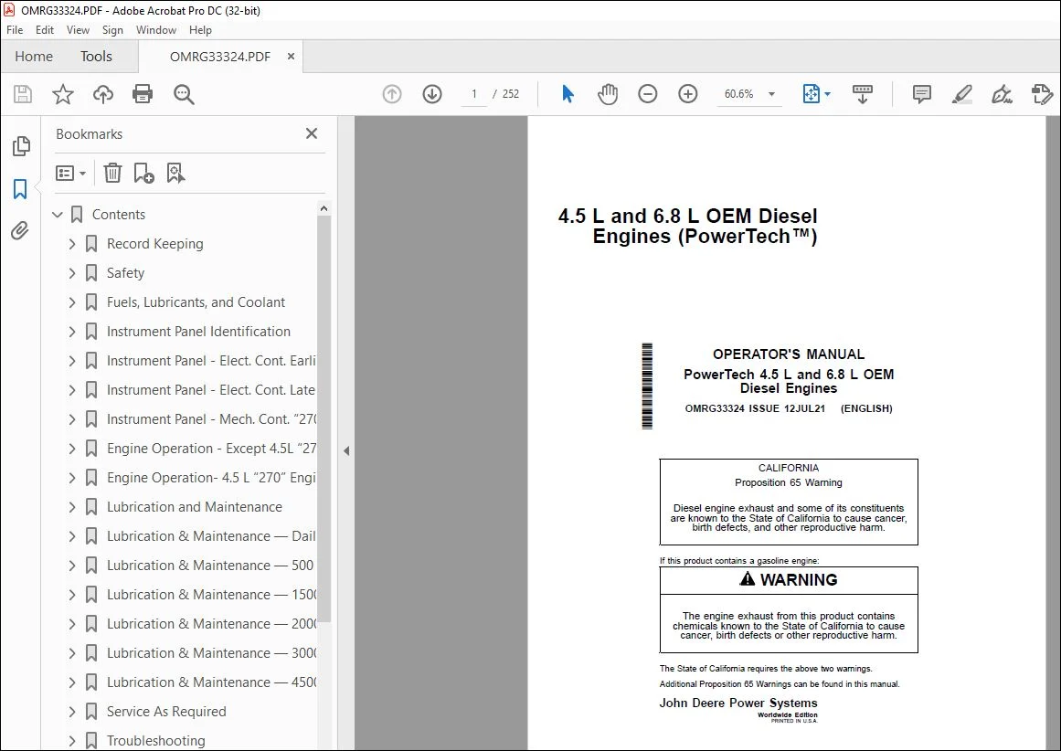
John Deere 4.5 L & 6.8 L OEM Engines (PowerTech™) Operator’s Manual PDF
$28.95
John Deere 4.5 L & 6.8 L OEM Diesel Engines (PowerTech™) Operator’s Manual OMRG33324 – PDF DOWNLOAD
Description
John Deere 4.5 L & 6.8 L OEM Diesel Engines (PowerTech™) Operator’s Manual OMRG33324 – PDF DOWNLOAD
FILE DETAILS:
John Deere 4.5 L & 6.8 L OEM Diesel Engines (PowerTech™) Operator’s Manual OMRG33324 – PDF DOWNLOAD
- P/N: OMRG33324_61
- Language: English
- Division: Construction
- Product Lines: Engines
- Publication Type: Operator’s Manuals
- Associated Models: 4.5L, 6.8L, 4045DF270, 4045HF275, 4045TF270, 4045TF275, 6068HF275, 6068TF275
- Series: POWERTECH POWERTECH 4.5 & 6.8L — 4045 and 6068 Elec-Controlled Tier 2/Stage II OEM Diesel Engines
IMAGES PREVIEW OF THE MANUAL:
TABLE OF CONTENTS:
John Deere 4.5 L & 6.8 L OEM Diesel Engines (PowerTech™) Operator’s Manual OMRG33324 – PDF DOWNLOAD
Contents 11
Record Keeping 15
Medallion 15
Engine Serial Number Plate 15
Record Engine Serial Number 16
Engine Option Codes 17
Record Engine Control Unit (ECU) Serial Number 19
Record Fuel Injection Pump Information 19
Safety 20
Recognize Safety Information 20
Understand Signal Words 20
Follow Safety Instructions 20
Replace Safety Signs 21
California Proposition 65 Warning 21
Illuminate Work Area Safely 21
Work in Clean Area 21
Use Proper Tools 22
Live With Safety 22
Prevent Machine Runaway 22
Handle Fuel Safely—Avoid Fires 23
Prepare for Emergencies 23
Handle Starting Fluid Safely 23
In Case of Fire 24
Handle Fluids Safely—Avoid Fires 24
Avoid Static Electricity Risk When Refueling 25
Service Machines Safely 25
Wear Protective Clothing 25
Protect Against Noise 26
Handling Batteries Safely 26
Prevent Acid Burns 27
Stay Clear of Rotating Drivelines 27
Install All Guards 28
Practice Safe Maintenance 28
Remove Paint Before Welding or Heating 29
Avoid Heating Near Pressurized Fluid Lines 29
Avoid High-Pressure Fluids 29
Do Not Open High-Pressure Fuel System 30
Protect Against High Pressure Spray 30
Prevent Battery Explosions 30
Avoid Hot Exhaust 31
Work In Ventilated Area 31
Service Cooling System Safely 31
Decommissioning — Proper Recycling and Disposal of Fluids and Components 32
Fuels, Lubricants, and Coolant 33
Diesel Fuel 33
Supplemental Diesel Fuel Additives 34
Lubricity of Diesel Fuel 34
Handling and Storing Diesel Fuel 34
Biodiesel Fuel 35
Testing Diesel Fuel 36
Fuel Filters 36
Minimizing the Effect of Cold Weather on Diesel Engines 37
Diesel Engine Break-In Oil — Non-Emissions Certified and Certified Tier 1, Tier 2, Tier 3, Stage I, Stage II, and Stage III 38
Diesel Engine Oil — Tier 2 and Stage II 39
Engine Oil and Filter Service Intervals — Tier 2 and Stage II — OEM Applications 40
Mixing of Lubricants 40
Alternative and Synthetic Lubricants 41
Lubricant Storage 41
Oil Filters 41
Diesel Engine Coolant (engine with wet sleeve cylinder liners) 42
Water Quality for Mixing with Coolant Concentrate 43
Operating in Warm Temperature Climates 43
Testing Coolant Freeze Point 44
Disposing of Coolant 44
Instrument Panel Identification 45
Instrument Panels – Identification 45
Instrument Panel – Elect Cont Earlier Engines 47
Instrument Panel 47
Using Diagnostic Gauge to Access Engine Information 53
Using Touch Switches to Display Information 54
Changing Units of Measure (English or Metric) 56
Viewing Engine Configuration Data 58
Viewing Active Engine Service Codes/Diagnostic Trouble Codes (DTCs) 60
Viewing Stored Service Codes/Diagnostic Trouble Codes (DTCs) in the Engine ECU 61
Instrument Panel – Elect Cont Later Engines 62
PV101 Instrument Panels 62
PV101 Diagnostic Gauge — Using 64
PV101 Diagnostic Gauge — Main Menu 65
PV101 Diagnostic Gauge — Essential Menus 66
DG14 Diagnostic Gauge — Using 66
DG14 Diagnostic Gauge — Main Menu 67
DG14 Diagnostic Gauge — Essential Menus 68
PV480 Instrument Panel 69
PV480 Diagnostic Gauge — Using 70
PV480 Diagnostic Gauge — Main Menu 71
PV480 Diagnostic Gauge — Essential Menus 72
Main Menu Navigation 72
Engine Configuration Data 74
Accessing Stored Trouble Codes 75
Accessing Active Trouble Codes 77
Engine Shutdown Codes 79
Adjusting Backlighting 80
Adjusting Contrast 82
Selecting Units Of Measurement 84
Setup 1-Up Display 86
Setup 4-Up Display 91
Instrument Panel – Mech Cont “270” Engines 96
Instrument Panel (Earlier 4 5 L “270” Engines) 96
Instrument Panel (Later 4 5 L “270” Engines) 97
Engine Operation – Except 4 5L “270” Engines 98
Engine Break-In Service 98
Starting the Engine 100
Normal Engine Operation 101
Warming Engine 102
Cold Weather Operation 103
Using a Booster Battery or Charger 104
Avoid Excessive Engine Idling 105
Changing Engine Speed 106
Stopping The Engine 108
Auxiliary Gear Drive Limitations 109
Generator Set (Standby) Applications 109
Engine Operation- 4 5 L “270” Engines 110
Normal Engine Operation 110
Break-In Service 110
Auxiliary Gear Drive Limitations 112
Generator Set (Standby) Power Units 112
Starting The Engine 112
Cold Weather Starting 113
Warming Engine 114
Avoid Excessive Engine Idling 114
Stopping the Engine 115
Using a Booster Battery or Charger 116
Lubrication and Maintenance 117
Required Emission-Related Information 117
Observe Service Intervals 117
Use Correct Fuels, Lubricants, and Coolant 117
Lubrication and Maintenance Service Interval Chart 118
Lubrication & Maintenance — Daily 120
Daily Prestarting Checks 120
Lubrication & Maintenance — 500 Hours/12 Months 124
Servicing Fire Extinguisher 124
Checking Engine Mounts 124
Servicing Battery 125
Manual Belt Tensioner Adjustment 127
Manual Belt Tensioner Adjustment Using Belt Tension Tool (Alternate Method For Engines Without Auxiliary Drive) 128
Changing Engine Oil and Replacing Filter 130
Checking Crankcase Vent System 132
Checking Air Intake System 134
Replacing Fuel Filter Elements 135
Checking Belt Tensioner Spring Tension and Belt Wear (Automatic Tensioner) 137
Checking Engine Electrical Ground Connections 138
Checking Cooling System 139
Replenishing Supplemental Coolant Additives (SCAs) Between Coolant Changes 140
Testing Diesel Engine Coolant 141
Pressure Testing Cooling System 142
Checking and Adjusting Engine Speeds 143
Lubrication & Maintenance — 1500 Hours 144
Checking Crankshaft Vibration Damper (If Equipped) 144
Lubrication & Maintenance — 2000 Hours/24 Months 146
Adjusting Variable Speed (Droop) — Generator Set Engines Only 146
Flushing and Refilling Cooling System 147
Testing Thermostats Opening Temperature 149
Check and Adjust Valve Clearance 164
Check and Adjust Valve Clearance (4045HF475 And 6068HF475 Engines) 169
Test Glow Plugs for Continuity 171
Lubrication & Maintenance — 3000 Hours 172
Checking Crankshaft Vibration Damper (If Equipped) 172
Lubrication & Maintenance — 4500 Hours/36 Months 174
Replace Crankshaft Vibration Damper 174
Service As Required 175
Additional Service Information 175
Do Not Modify Fuel System 175
Adding Coolant 176
Pre-Start Cleaning Guide 177
Replacing Single Stage Air Cleaner 178
Replacing Axial Seal Air Cleaner Filter Element 179
Replacing Radial Seal Air Cleaner Filter Element 181
Replacing Fan and Alternator Belts 182
Checking Fuses 183
Checking Air Compressors (If Equipped) 183
Bleeding the Fuel System (Engines With Electronic Fuel Systems And Bosch VP44 Pump) 184
Bleed the Fuel System (Engines with Electronic Fuel Systems and Stanadyne DE10 Pump) 185
Bleed the Fuel System (Engines with Electronic Fuel Systems and Denso High Pressure Common Rail) (4045HF475, 6068HF475) 188
Bleeding the Fuel System 189
Troubleshooting 192
General Troubleshooting Information 192
Precautions For Welding 192
Precautions for Electrical System When Steam Cleaning Engine 192
Engine Wiring Layout (Electronic Fuel System With Stanadyne DE10 Injection Pump) 193
Engine Wiring Layout (Electronic Fuel System With Bosch VP44 Injection Pump) 194
Engine Wiring Layout (Electronic Fuel System With Denso High Pressure Common Rail)(4045HF475,6068HF475) 195
Engine Wiring Diagram (With Earlier Electronic Instrument Panel) 196
Engine Wiring Diagram (With Earlier Electronic Instrument Panel)—Continued 197
Engine Wiring Diagram (With Later Full-Featured Electronic Instrument Panel) 198
Engine Wiring Diagram (With Later Full-Featured Electronic Instrument Panel)—Continued 199
Engine Troubleshooting 200
Blink Code Method for Retrieving Diagnostic Trouble Codes (All Except Early VP44 Pump Engines) 205
Blink Code Method for Retrieving Diagnostic Trouble Codes (Early VP44 Pump Engines Only) 206
Instrument Panel Method for Retrieving Diagnostic Trouble Codes 207
Displaying Of Diagnostic Trouble Codes (DTCs) 207
Listing of Diagnostic Trouble Codes (DTCs) (Engines With Electronic Fuel Systems And Stanadyne DE10 Pump) 208
Listing of Diagnostic Trouble Codes (DTCs) (Engines With Electronic Fuel Systems And Bosch VP44 Pump) 210
Listing of Diagnostic Trouble Codes (DTCs) (Engines With Electronic Fuel Systems And Denso High Pressure Common Rail) (“475” Engines) 212
Error Codes Displayed (With Early Electronic Panels) 214
Intermittent Fault Diagnostics (With Electronic Controls) 214
Displaying Diagnostic Gauge Software (Later Engines) 215
Storage 217
Engine Storage Guidelines 217
Preparing Engine for Long-Term Storage 217
Removing Engine from Long Term Storage 218
Specifications 219
General OEM Engine Specifications 219
Engine Power Ratings And Fuel System Specifications — 4045 221
Engine Power Ratings And Fuel System Specifications — 6068 223
Engine Crankcase Oil Fill Quantities 224
Unified Inch Bolt and Screw Torque Values 225
Metric Bolt and Screw Torque Values 226
Lubrication and Maintenance Records 227
Using Lubrication and Maintenance Records 227
Daily (Prestarting) Service 227
500 Hour/12 Month Service 227
1500 Hour Service 228
2000 Hour/24 Month Service 228
3000 Hour Service 229
4500 Hours/60 Months Service 229
Service as Required 230
Warranty 231
John Deere Warranty in OEM Applications 231
Emissions Control System Certification Label 234
EPA Non-road Emissions Control Warranty Statement—Compression Ignition 235
CARB Non-road Emissions Control Warranty Statement—Compression Ignition 237
John Deere Service Literature Available 245
Technical Information 245
Page Number 11
Section 01 15
Section 05 20
Section 10 33
Section 15 45
Section 16 47
Section 17 62
Section 18 96
Section 19 98
Section 20 110
Section 21 117
Section 25 120
Section 30 124
Section 34 144
Section 35 146
Section 36 172
Section 37 174
Section 40 175
Section 45 192
Section 50 217
Section 55 219
Section 60 227
Section 65 231
Section 70 245
S.V 04/24