John Deere 410E Backhoe Loader Repair Technical Manual – PDF DOWNLOAD
Original price was: $87.95.$28.95Current price is: $28.95.
John Deere 410E Backhoe Loader Repair Technical Manual – PDF DOWNLOAD
Description
John Deere 410E Backhoe Loader Repair Technical Manual – PDF DOWNLOAD
DESCRIPTION:
John Deere 410E Backhoe Loader Repair Technical Manual – PDF DOWNLOAD
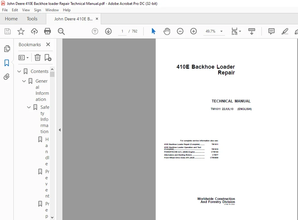
For complete service information also see:
410E Backhoe Loader Repair (Complete) ……… TM1611
410E Backhoe Loader Operation and Test
(Complete)…………………………………………………… TM1610
POWERTECH® 4.5 L (4045) Engine………………. CTM104
Alternators and Starting Motors …………………… CTM77
Front Wheel Drive Axles APL2025………………..
CTM4509
Foreword :
This manual is written for an experienced technician. Essential tools required in performing certain service work are identified in this manual and are recommended for use. Live with safety: Read the safety messages in the introduction of this manual and the cautions presented throughout the text of the manual.
- This is the safetyalert symbol. When you see this symbol on the machine or in this manual, be alert to the potential for personal injury. Technical manuals are divided in two parts: repair and operation and tests. Repair sections tell how to repair the components.
- Operation and tests sections help you identify the majority of routine failures quickly. Information is organized in groups for the various components requiring service instruction. At the beginning of each group are summary listings of all applicable essential tools, service equipment and tools, other materials needed to do the job, service parts kits, specifications, wear tolerances, and torque values.
- Technical Manuals are concise guides for specific machines. They are onthejob guides containing only the vital information needed for diagnosis, analysis, testing, and repair. Fundamental service information is available from other sources covering basic theory of operation, fundamentals of troubleshooting, general maintenance, and basic type of failures and their causes.
See DB1990 Service Publications Catalog to order a complete Technical Manual (TM) or a Technical Manual Section (TMS). A complete Repair manual includes the following sections:
• TMS161100 Section 00 General Information
• TMS161101 Sections 01—02 Wheels and Axles
• TMS161103 Sections 03—06 Transmission and Engine
• TMS161109 Sections 09—11 Steering and Brakes
• TMS161116 Sections 16—17 Electrical System and
Frame
• TMS161118 Sections 18—20 Operator’s Station and
Sheet Metal
• TMS161121 Sections 21, 31, 33 Main Hydraulics
TABLE OF CONTENTS:
John Deere 410E Backhoe Loader Repair Technical Manual – PDF DOWNLOAD
Contents……………………………………………………………… 5
General Information………………………………………………… 7
Safety Information……………………………………………… 9
Handle Fluids Safely—Avoid Fires……………………………… 9
Prevent Battery Explosions…………………………………… 9
Prepare for Emergencies……………………………………… 9
Prevent Acid Burns………………………………………….. 10
Handle Chemical Products Safely………………………………. 10
Avoid High-Pressure Fluids…………………………………… 11
Park Machine Safely…………………………………………. 11
Support Machine Properly…………………………………….. 11
Wear Protective Clothing…………………………………….. 12
Work in Clean Area………………………………………….. 12
Service Machines Safely……………………………………… 12
Work In Ventilated Area……………………………………… 13
Illuminate Work Area Safely………………………………….. 13
Replace Safety Signs………………………………………… 13
Use Proper Lifting Equipment…………………………………. 14
Remove Paint Before Welding or Heating………………………… 14
Avoid Heating Near Pressurized Fluid Lines…………………….. 14
Keep ROPS Installed Properly…………………………………. 15
Service Tires Safely………………………………………… 15
Practice Safe Maintenance……………………………………. 16
Use Proper Tools……………………………………………. 16
Dispose of Waste Properly……………………………………. 17
Live With Safety……………………………………………. 17
General Specifications………………………………………….. 19
410E Backhoe Loader Dimensions……………………………….. 19
410E Backhoe Loader Specifications……………………………. 24
Other Information—410E Backhoe Loader…………………………. 26
410E Backhoe Loader Weight…………………………………… 26
410E Backhoe and Loader Buckets………………………………. 27
410E Backhoe Loader Drain and Refill Capacities………………… 27
410E Backhoe Loader Lifting Capacities—Standard Dipperstick……… 28
410E Backhoe Loader Lifting Capacities—Extendible Dipperstick (R…. 29
410E Backhoe Loader Lifting Capacities—Extendible Dipperstick (E…. 30
Torque Values………………………………………………….. 31
Hardware Torque Specifications……………………………….. 31
ROPS Torque Specifications…………………………………… 31
Metric Bolt and Screw Torque Values…………………………… 32
Additional Metric Cap Screw Torque Values……………………… 33
Unified Inch Bolt and Screw Torque Values……………………… 34
O-Ring Groove Connections……………………………………. 35
Check Oil Lines And Fittings…………………………………. 35
Service Recommendations for O-Ring Boss Fittings……………….. 36
Service Recommendations for Flat Face O-Ring Seal Fittings………. 37
Service Recommendations for Metric Series Four Bolt Flange Fitti…. 38
Service Recommendations For Inch Series Four Bolt Flange Fitting…. 39
Fuels and Lubricants……………………………………………. 41
Diesel Fuel………………………………………………… 41
Low Sulfur Diesel Fuel Conditioner……………………………. 41
Handling and Storing Diesel Fuel……………………………… 42
Do Not Use Galvanized Containers……………………………… 42
Heavy Duty Diesel Engine Coolant……………………………… 43
Fuel Tank………………………………………………….. 43
Diesel Engine Oil…………………………………………… 44
Transmission, Axle, and Mechanical Front Wheel Drive Oil………… 45
Hydraulic Oil………………………………………………. 45
Grease…………………………………………………….. 47
Grease for Extendible Dipperstick, Sideshift Frame, and Stabiliz…. 47
Alternative and Synthetic Lubricants………………………….. 47
Lubricant Storage…………………………………………… 48
Mixing of Lubricants………………………………………… 48
Wheels……………………………………………………………. 49
Powered or Non-Powered Wheels and Fastenings………………………. 51
Service Equipment and Tools………………………………….. 51
Specifications……………………………………………… 51
Remove and Install Rear Wheel Assembly………………………… 52
Remove and Install Front Wheel Assembly……………………….. 53
Remove and Install Tire……………………………………… 54
Axles and Suspension Systems………………………………………… 57
Input Drive Shafts and U-Joints………………………………….. 59
Specifications……………………………………………… 59
Remove and Install Drive Shaft……………………………….. 59
Non-Powered Wheel Axles…………………………………………. 61
Service Equipment and Tools………………………………….. 61
Other Material……………………………………………… 61
Specifications……………………………………………… 61
Remove and Install Hub Assembly………………………………. 62
Remove and Install Spindle and Knuckle Assembly………………… 63
Remove and Install Tie Rod…………………………………… 64
Remove and Install Non-Powered Front Axle……………………… 64
Adjust Non-Powered Front Axle Toe-In………………………….. 65
Powered Wheel Axle (MFWD)……………………………………….. 67
Service Equipment and Tools………………………………….. 67
Other Material……………………………………………… 67
Specifications……………………………………………… 67
Front Wheel Drive Axles—Use CTM4509…………………………… 67
Remove and Install Powered Front Axle…………………………. 68
Adjust MFWD Axle Toe-In……………………………………… 70
Axle Shaft, Bearings and Reduction Gears………………………….. 71
Essential Tools…………………………………………….. 71
Service Equipment and Tools………………………………….. 71
Other Material……………………………………………… 72
Specifications……………………………………………… 73
Inspect Service Brakes………………………………………. 74
Remove and Install Rear Axle…………………………………. 75
Disassemble Rear Axle……………………………………….. 76
Disassemble and Assemble Park Brake…………………………… 85
Assemble Rear Axle…………………………………………..102
Check Service Brakes After Assembly……………………………121
Check Gear Tooth Contact Pattern………………………………122
Dealer Fabricated Tools………………………………………….123
DFT1146 Axle Mounting Bracket…………………………………123
DFT1147 Axle Rolling Torque Bar……………………………….123
Transmission……………………………………………………….126
Removal and Installation…………………………………………127
Specifications………………………………………………127
Remove and Install Transmission……………………………….127
Controls Linkage………………………………………………..131
Other Material………………………………………………131
Specifications………………………………………………131
Remove and Install Reverser Control……………………………132
Remove and Install Transmission Shifter Lever…………………..133
Remove Shifter Lever and Housing………………………………134
Disassemble and Assemble Shift Lever and Housing………………..136
Install Shift Lever and Housing……………………………….139
Input Drive Shafts and U-Joint……………………………………141
Specifications………………………………………………141
Remove and Install Drive Shaft………………………………..141
Gears, Shafts, Bearings, and Powershift Clutches……………………143
Essential Tools……………………………………………..143
Service Equipment and Tools…………………………………..143
Other Material………………………………………………144
Other Material………………………………………………145
Specifications………………………………………………146
Remove Outer Components to Disassemble Manual Shift Transmission….147
Disassemble Converter Side of Case—Manual Shift…………………151
Remove Oil Suction Tube—Manual Shift…………………………..154
Remove Reverse and Forward Clutch Packs—Manual Shift…………….154
Disassemble and Assemble Reverse or Forward Clutch Pack—Manual S….154
Remove Drive Shaft—Manual Shift……………………………….164
Disassemble and Assemble Drive Shaft—Manual Shift……………….164
Remove Rear Output Shaft with Synchronizer—Manual Shift………….166
Remove Intermediate Shaft with Synchronizer—Manual Shift…………167
Disassemble Rear Output or Intermediate Shaft with Synchronizer—….167
Rear Output Shaft—Cross Section View—Manual Shift……………….172
Intermediate Shaft—Cross Section View—Manual Shift………………173
Assemble Rear Output or Intermediate Shaft—Manual Shift………….174
Remove MFWD Output Shaft (If Equipped)—Manual Shift……………..180
Disassemble MFWD Shaft (If Equipped)—Manual Shift……………….180
MFWD Shaft—Cross Section View—Manual Shift……………………..183
Assemble MFWD Shaft (If Equipped)—Manual Shift………………….184
Remove, Disassemble, and Assemble Idler Shaft—Manual Shift……….186
Remove and Install Oil Supply Tube—Manual Shift…………………187
Install Idler and MFWD Shafts to Assemble Transmission (If Equip….187
Install Intermediate and Rear Output Shafts—Manual Shift…………190
Install Drive Shaft—Manual Shift………………………………191
Install Forward and Reverse Clutch Packs—Manual Shift……………192
Install Oil Suction Tube—Manual Shift………………………….194
Assemble Converter Side of Case—Manual Shift……………………194
Install Outer Components to Assemble Transmission—Manual Shift……197
Remove Outer Components to Disassemble Powershift Transmission……205
Disassemble Converter Side of Case—Powershift…………………..207
Remove Low Range Forward, Reverse and Third Speed Clutch Packs—P….209
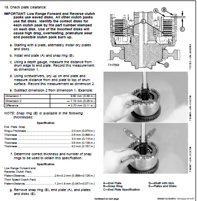
Disassemble and Assemble Low Range Forward, Reverse and Third Sp….210
Remove First Speed, Second Speed, and High Range Forward Clutch ….220
Disassemble and Assemble First Speed, Second Speed, and High Ran….220
Remove Drive Shaft—Powershift…………………………………229
Disassemble and Assemble Drive Shaft—Powershift…………………230
Remove MFWD Output Shaft (If Equipped)—Powershift……………….231
Disassemble MFWD Shaft (If Equipped)—Powershift…………………233
Assemble MFWD Shaft (If Equipped)—Powershift……………………235
Remove Oil Suction Tube—Powershift…………………………….237
Remove and Install Oil Supply Tubes—Powershift………………….238
Install Oil Suction Tube—Powershift……………………………239
Install MFWD Shaft to Assemble Transmission (If Equipped)—Powers….239
Install Drive Shaft—Powershift………………………………..240
Install Clutch Packs—Powershift……………………………….241
Assemble Converter Side of Case—Powershift……………………..242
Install Outer Components to Assemble Transmission—Powershift……..246
Hydraulic System………………………………………………..251
Other Material………………………………………………251
Specifications………………………………………………251
Remove and Install Control Valve—Manual Shift…………………..252
Disassemble and Assemble Control Valve—Manual Shift……………..252
Remove and Install Transmission Charge Pump—Manual Shift…………262
Remove and Install Transmission Charge Pump—Powershift…………..262
Disassemble and Assemble Transmission Charge Pump—Manual Shift a….262
Remove and Install Manifold Plate Solenoids—Manual Shift…………266
Remove and Install Control Valve—Powershift…………………….268
Disassemble and Assemble Control Valve—Powershift……………….269
Remove and Install Shift Valve—Powershift………………………278
Disassemble and Assemble Shift Valve—Powershift…………………279
Remove and Install Manifold Plate and Solenoids—Powershift……….284
Dealer Fabricated Tools………………………………………….287
DFT1143 Transmission Support Bracket…………………………..287
DFT1162 Powershift Clutch Pack Snap Ring Removal and Installatio….288
DFT1163 MFWD Snap Ring Removal and Installation Tool…………….289
Engine…………………………………………………………….291
Removal and Installation…………………………………………293
Essential Tools……………………………………………..293
Specifications………………………………………………293
PowerTech 4.5 L (4045) John Deere Engine—Use CTM104……………..294
Remove and Install Engine…………………………………….294
Dealer Fabricated Tools………………………………………….305
DFT1145 Transmission Holding Bracket…………………………..305
Engine Auxiliary Systems…………………………………………….307
Cold Weather Starting Aid………………………………………..309
Specifications………………………………………………309
Remove and Install Coolant Heater……………………………..309
Remove and Install Starting Aid Nozzle…………………………310
Remove and Install Starting Aid Solenoid……………………….312
Cooling Systems…………………………………………………313
Specifications………………………………………………313
Remove and Install Fan……………………………………….313
Remove and Install Fan Belt…………………………………..314
Remove and Install Radiator…………………………………..314
Speed Controls………………………………………………….317
Specifications………………………………………………317
Disassemble and Assemble Speed Control Linkage………………….318
Intake System…………………………………………………..321
Essential Tools……………………………………………..321
Service Equipment and Tools…………………………………..321
Specifications………………………………………………321
Remove and Install Air Cleaner………………………………..322
Air Intake System Leakage Test………………………………..323
Exhaust System………………………………………………….325
Remove And Install Muffler……………………………………325
Remove And Install Muffler With Turbocharger—If Equipped…………326
External Fuel Supply System………………………………………327
Other Material………………………………………………327
Remove and Install Fuel Tank………………………………….328
Torque Converter……………………………………………………331
Turbine, Gears and Shaft…………………………………………333
Remove and Install Torque Converter……………………………333
Disassemble and Assemble Torque Converter………………………333
Steering System…………………………………………………….335
Hydraulic System………………………………………………..337
Service Equipment and Tools…………………………………..337
Other Material………………………………………………337
Specifications………………………………………………338
Remove and Install Steering Column…………………………….339
Disassemble and Assemble Tilt Steering Wheel and Column………….340
Remove and Install Steering Valve……………………………..341
Remove and Install Pressure Regulating Valve from Steering Valve….344
Disassemble and Assemble Pressure Regulating Valve………………345
Disassemble Steering Valve……………………………………345
Assemble Steering Valve………………………………………351
Remove and Install Non-Powered Axle Steering Cylinder……………356
Disassemble Non-Powered Axle Steering Cylinder………………….356
Cross Section of Non-Powered Axle Steering Cylinder……………..359
Assemble Non-Powered Axle Steering Cylinder…………………….359
Remove and Install Steering Cylinder Bushings…………………..365
Cross Section of APL-2025 MFWD Axle Steering Cylinder……………366
Disassemble and Assemble APL-2025 MFWD Axle Steering Cylinder…….367
Adjust Tracking Angle for MFWD Axle……………………………372
Remove and Install Priority Valve……………………………..372
Disassemble and Assemble Priority Valve………………………..374
Service Brakes……………………………………………………..377
Active Elements…………………………………………………379
External Service Brake Inspection……………………………..379
Remove and Install Brake Disk and Pressure Plate………………..379
Hydraulic System………………………………………………..381
Service Equipment and Tools…………………………………..381
Other Material………………………………………………381
Specifications………………………………………………382
Remove and Install John Deere Brake Valve (S.N. —887378)…………383
Disassemble and Assemble John Deere Brake Valve (S.N.—887378)…….384
Disassemble and Assemble Brake Valve Lines (S.N.—887378)…………386
Remove and Install MICO Brake Valve (S.N. 887379—)………………387
Disassemble MICO Power Boost Brake Valve (S.N. 887379—)………….390
Assemble MICO Power Boost Brake Valve (S.N. 887379—)…………….392
Adjust Brake Pedals………………………………………….394
Bleeding Brakes……………………………………………..396
Park Brake…………………………………………………………397
Active Elements…………………………………………………399
Remove and Install Park Brake…………………………………399
Electrical Systems………………………………………………….401
Batteries, Support, and Cables……………………………………403
Service Equipment and Tools…………………………………..403
Specifications………………………………………………403
Service Batteries Carefully…………………………………..404
Procedure for Testing Batteries……………………………….405
Electrolyte Checking Specific Gravity………………………….406
Battery Electrolyte Level and Terminals Check…………………..407
Battery Charger—Using………………………………………..409
Using Booster Batteries—12 Volt System…………………………410
Charge Battery………………………………………………411
Remove and Install Batteries………………………………….412
Alternator, Regulator and Charging System Wiring……………………415
Bosch Alternator Repair—Use CTM77……………………………..415
Specifications………………………………………………415
Remove and Install Alternator…………………………………416
Lighting System…………………………………………………419
Remove and Install Drive and Work Light………………………..419
Remove and Install Halogen Bulb……………………………….419
Remove and Install Display Module Bulbs………………………..420
Remove and Install Turn, Brake and Tail Light Bulbs……………..421
Remove and Install Front Turn Light Bulb……………………….421
Wiring Harness and Switches………………………………………423
Essential Tools……………………………………………..423
Specifications………………………………………………424
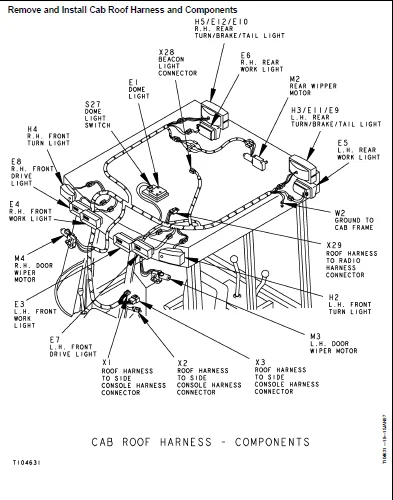
Remove and Install Cab Roof Harness and Components………………425
Remove and Install Cab Side Console Harness and Components……….427
Remove and Install Front Console Harness and Components………….431
Remove and Install Engine Harness and Components………………..433
Remove and Install Blower Harness and Components………………..435
Remove and Install Radio Harness and Components…………………437
Remove and Install A/C Compressor Harness and Components—If Equi….439
Remove and Install Auxiliary Flow Control Harness and Components….441
Remove and Install Ride Control Harness and Components—If Equipp….442
Fuse Specifications………………………………………….443
Kostal Connector 16 Way Replace……………………………….443
Kostal Open-Barrel Contact Install…………………………….444
Replace DEUTSCH DEUTSCH is a trademark of Deutsch Co.™ Connector….445
Install DEUTSCH DEUTSCH is a trademark of Deutsch Co.™ Contact ….447
Replace WEATHER PACK WEATHER PACK is a trademark of Packard Elec….448
WEATHER PACK WEATHER PACK is a trademark of Packard Electric.™ ….449
Remove Connector Body from Blade Terminals……………………..450
Remove Blade Terminals from Fuse Block ………………………..451
System Controls…………………………………………………453
Remove and Install Return-to-Dig Switch………………………..453
Instruments and Indicators……………………………………….455
Other Material………………………………………………455
Remove and Install Fuel Gauge Sender…………………………..455
Motors and Actuators…………………………………………….457
Starter Motor Repair—Use CTM77………………………………..457
Remove and Install Starting Motor……………………………..457
Remove and Install Starter Relay………………………………458
Frames, Chassis or Supporting Structure……………………………….459
Frame Installation………………………………………………461
Essential Tools……………………………………………..461
Specifications………………………………………………461
Welding Repair of Major Structures…………………………….461
Remove and Install RIVNUTRIVNUT is a registered trademark of The….462
Chassis Weights…………………………………………………465
Specifications………………………………………………465
Remove and Install Counterweight………………………………466
Remove and Install Frame Bumper……………………………….467
Operator’s Station………………………………………………….469
Removal and Installation…………………………………………471
Service Equipment and Tools…………………………………..471
Specifications………………………………………………471
Remove and Install Cab/ROPS…………………………………..471
Operator Enclosure………………………………………………477
Other Material………………………………………………477
Specifications………………………………………………477
Disassemble and Assemble Fixed Right Front Cab Window and Wiper ….478
Disassemble and Assemble Right Cab Door and Wiper Motor………….480
Disassemble and Assemble Left Cab Door and Wiper Motor…………..482
Adjust Cab Right Door Latch and Hinges…………………………484
Adjust Cab Left Door Latch and Hinges………………………….486
Adjust Cab Door Handle Screw………………………………….487
Disassemble and Assemble Cab Side Windows………………………488
Adjust Cab Side Windows………………………………………489
Disassemble and Assemble Upper Rear Window and Wiper Motor……….490
Adjust Upper Rear Window……………………………………..491
Disassemble and Assemble Lower Rear Windows…………………….492
Adjust Lower Rear Window……………………………………..493
Remove and Install Windowpanes………………………………..493
Remove and Install Headliner………………………………….494
Remove and Install Cab Roof…………………………………..495
Seat and Seat Belt………………………………………………497
Specifications………………………………………………497
Remove and Install Seat Assembly………………………………497
Seat and Seat Belt and Arm Rest—Disassemble and Assemble…………498
Seat Slide and Swivel and Lumbar Control Levers—Disassemble and ….500
Seat Swivel and Latch Disassemble and Assemble………………….502
Disassemble and Assemble Seat Suspension and Shock Absorber………504
Disassemble and Assemble Seat Base and Support………………….506
Disassemble and Assemble Air Seat Suspension (If Equipped)……….507
Heating and Air Conditioning……………………………………..513
Essential Tools……………………………………………..513
Service Equipment and Tools…………………………………..514
Other Material………………………………………………515
Specifications………………………………………………516
Proper Refrigerant Handling…………………………………..516
R134a Refrigerant Cautions……………………………………517
Refrigerant Hoses and Tubing Inspection………………………..517
Refrigerant Theory of Operation……………………………….518
Remove and Install Air Conditioning Compressor………………….519
R134a Compressor Oil Removal………………………………….519
Disassemble and Assemble Compressor Clutch……………………..520
Clutch Hub Clearance Check……………………………………521
Compressor Manifold Inspect…………………………………..521
Disassemble, Inspect, and Assemble Compressor…………………..522
R134a Component Oil Charge……………………………………524
R134a Refrigerant Recovery/Recycling and Charging Station Instal….525
Recover R134a System…………………………………………526
Evacuate R134a System………………………………………..527
Charge R134a System………………………………………….528
R134a System Leak Testing…………………………………….528
Remove and Install Heater Core………………………………..529
Remove and Install Evaporator…………………………………530
Remove and Install A/C Freeze Switch…………………………..531
Disassemble and Assemble Heater/Blower Assembly…………………532
Disassemble and Assemble Heater/Blower Assembly with Air Conditi….533
Disassemble and Assemble Blower Assembly……………………….534
Disassemble and Assemble Condenser…………………………….535
Disassemble and Assemble Air Ducts…………………………….537
Dealer Fabricated Tools………………………………………….539
DFRW20 Compressor Holding Fixture……………………………..539
DFT1101 Cab and ROPS Lift Bracket……………………………..540
Sheet Metal and Styling……………………………………………..541
Hood and Engine Enclosure………………………………………..543
Disassemble and Assemble Hood and Engine Enclosure………………543
Miscellaneous Shields……………………………………………545
Disassemble and Assemble Battery Box…………………………..545
Grille and Grille Housing………………………………………..547
Disassemble and Assemble Grille and Grille Housing………………547
Fenders………………………………………………………..549
Disassemble and Assemble Fenders………………………………549
Disassemble and Assemble Fender Extensions……………………..550
Safety, Convenience and Miscellaneous…………………………………551
Radio………………………………………………………….553
Remove and Install Radio and Speakers………………………….553
Remove and Install Antenna……………………………………553
Disassemble and Assemble Radio, Speakers and Antenna…………….554
Horn and Warning Devices…………………………………………557
Remove and Install Horn………………………………………557
Remove and Install Back-Up Alarm………………………………558
Adjust Back-Up Alarm Volume…………………………………..558
Main Hydraulic System……………………………………………….559
Hydraulic System………………………………………………..561
Other Material………………………………………………561
Specifications………………………………………………562
Remove and Install Hydraulic Pump……………………………..563
Hydraulic Pump Cross Section………………………………….565
Hydraulic Pump Control Piston and Load Sense Module……………..567
Hydraulic Pump Flow Limiter…………………………………..569
Disassemble, Inspect and Assemble Hydraulic Pump………………..570
Remove and Install Hydraulic Filter Assembly……………………597
Remove and Install Reservoir………………………………….598
Disassemble and Assemble Reservoir…………………………….599
Remove and Install Hydraulic Oil Cooler (Standard without Air Co….601
Remove and Install Hydraulic Oil Cooler and Hoses with Air Condi….603
Loader…………………………………………………………….605
Loader…………………………………………………………607
Specifications………………………………………………607
Remove Loader……………………………………………….607
Install Loader………………………………………………610
Bucket…………………………………………………………613
Specifications………………………………………………613
Remove and Install Loader Bucket………………………………613
Replace Welded Bucket Cutting Edges……………………………614
Bucket Cutting Edge Cracked Repair…………………………….614
Remove and Install Cutting Edge……………………………….615
Disassemble and Assemble Multi-Purpose Bucket and Lines………….620
Control Linkages………………………………………………..623
Other Material………………………………………………623
Specifications………………………………………………623
Loader Bucket Self-Leveling Linkage Indicator and Return-to-Dig ….624
Remove and Install Loader Control Valve Linkage…………………626
Loader Control Valve Linkage Adjustment………………………..628
Remove and Install Bucket Cylinder Linkage……………………..629
Hydraulic System………………………………………………..631
Essential Tools……………………………………………..631
Service Equipment and Tools…………………………………..631
Other Material………………………………………………632
Specifications………………………………………………633
Disassemble and Assemble Loader Bucket Curl, Load Sense, Boom Ra….635
Disassemble and Assemble Loader Bucket Dump Circuit Relief Valve….636
Disassemble and Assemble Anti-Cavitation Valve………………….637
Disassemble and Assemble Auxiliary Circuit Relief Valve………….638
Disassemble and Assemble Auxiliary Shut-off Plug………………..638
Remove and Install Loader Control Valve………………………..639
Disassemble and Assemble Loader Control Valve…………………..640
Replace Wiper Rings and Seals of Loader Control Valve Sections……642
Remove and Install Loader Control Valve Relief Valves……………647
Disassemble and Assemble Loader Inlet Section…………………..648
Disassemble and Assemble Loader Bucket Section………………….650
Disassemble and Assemble Loader Boom Section……………………652
Disassemble and Assemble Loader Auxiliary Section……………….654
Remove and Install Loader Boom Cylinder—120 Series………………655
Remove and Install Loader Bucket Cylinder—120 Series…………….656
Disassemble Loader Bucket and Boom Cylinders—120 Series………….657
Cross Section of Loader Bucket and Boom Cylinder—120 Series………660
Assemble Loader Bucket and Boom Cylinder—120 Series……………..660
Disassemble and Assemble Multi-Purpose Bucket Cylinder—120 Serie….666
Remove and Install Ride Control Valve— If Equipped………………667
Disassemble and Assemble Ride Control Valve— If Equipped…………668
Remove and Install Ride Control Valve Solenoid—If Equipped……….671
Remove and Install Ride Control Accumulator—If Equipped………….671
Charging the Ride Control Accumulator………………………….673
Charging the Ride Control Accumulator—Procedure “A” (14.2 in. ac….674
Charging the Ride Control Accumulator—Procedure “B” (17.2 in. ac….675
Ride Control Accumulator—Discharge Procedure……………………676
Backhoe……………………………………………………………678
Bucket…………………………………………………………679
Service Equipment and Tools…………………………………..679
Remove and Install Bucket and Bucket Links……………………..679
Remove and Install Bucket Tooth Shank………………………….680
Remove and Install Bucket Cutting Edge…………………………683
Control Linkage…………………………………………………685
Other Material………………………………………………685
Specifications………………………………………………685
Remove and Install Backhoe Boom Swing Lock Control Lever and Lin….686
Remove and Install Backhoe Boom Swing Lock Arms and Locking Pin…..688
Remove and Install Backhoe Valve Linkage—Two Lever………………689
Backhoe Valve Linkage Adjustment………………………………690
Remove and Install Stabilizer Valve Linkage (S.N. —874256)……….691
Remove and Install Stabilizer Valve Linkage (S.N. 874257—)……….693
Stabilizer Valve Linkage Adjustment……………………………694
Frames…………………………………………………………695
Other Material………………………………………………695
Specifications………………………………………………695
Remove and Install Dipperstick………………………………..696
Remove and Install Boom………………………………………698
Remove and Install Swing Frame………………………………..702
Remove Extendible Dipperstick Extension………………………..703
Install Extendible Dipperstick Extension……………………….706
Hydraulic System………………………………………………..709
Essential Tools……………………………………………..709
Service Equipment and Tools…………………………………..709
Other Material………………………………………………710
Specifications………………………………………………711
Remove and Install Backhoe Control Valve……………………….713
Disassemble and Assemble Backhoe Control Valve………………….717
Remove and Install Backhoe Circuit Relief and System Relief Valv….719
Disassemble and Assemble Anti-Cavitation Valve………………….720
Disassemble and Assemble Backhoe Boom Raise, Bucket Dump, Crowd ….721
Disassemble and Assemble Backhoe Bucket Curl Circuit Relief Valv….722
Disassemble and Assemble Backhoe Swing, Boom Lower, Crowd In Cir….723
Disassemble and Assemble Backhoe Electro-Hydraulic Auxiliary Cir….724
Disassemble and Assemble Auxiliary Shut-off Plug………………..724
Disassemble and Assemble Backhoe Inlet Section………………….725
Disassemble and Assemble Backhoe Auxiliary Flow Section (If Equi….727
Disassemble and Assemble Backhoe Swing Section………………….729
Disassemble and Assemble Backhoe Boom Section…………………..731
Disassemble and Assemble Backhoe Bucket Section…………………733
Disassemble and Assemble Backhoe Crowd Section………………….735
Disassemble and Assemble Backhoe Extendible Section……………..737
Replace Wiper Rings and Seals of Backhoe Control Valve Sections…..738
Remove and Install Stabilizer Valve……………………………742
Disassemble and Assemble Stabilizer Valve………………………744
Remove and Install Backhoe Bucket Cylinder—125 Series……………745
Remove and Install Backhoe Crowd Cylinder—125 Series…………….746
Remove and Install Backhoe Boom Cylinder—125 Series……………..747
Remove and Install Extendible Dipperstick Cylinder………………749
Disassemble Boom, Bucket, and Crowd Cylinders—125 Series…………749
Cross Section of Backhoe Crowd (S.N. —837228) and Bucket Cylinde….751
Cross Section of Crowd Cylinder (S.N. 837229—873597) 125 Series…..752
Cross Section of Crowd Cylinder (S.N. 873598—) 125 Series………..753
Cross Section of Backhoe Boom Cylinder—125 Series……………….754
Assemble Boom, Bucket, and Crowd Cylinders—125 Series……………755
Indexing Series125 Cylinders………………………………….761
Remove and Install Swing Cylinder—120 Series……………………762
Remove and Install Stabilizer Cylinder—120 Series……………….764
Disassemble Swing and Stabilizer Cylinders—120 Series……………764
Cross Section of Swing Cylinder—120 Series……………………..767
Cross Section of Stabilizer Cylinder—120 Series…………………768
Assemble Swing and Stabilizer Cylinder—120 Series……………….768
Disassemble Extendible Dipperstick Cylinder…………………….774
Cross Section of Extendible Dipperstick Cylinder………………..777
Assemble Extendible Dipperstick Cylinder……………………….777
IMAGES PREVIEW OF THE MANUAL:
JOHN DEERE 410E BACKHOE LOADER REPAIR TECHNICAL MANUAL – PDF DOWNLOAD:
PLEASE NOTE:
- This is the SAME manual used by the dealers to troubleshoot any faults in your vehicle. This can be yours in 2 minutes after the payment is made.
- Contact us at [email protected] should you have any queries before your purchase or that you need any other service / repair / parts operators manual.
S.V