John Deere 444K Loader Repair Technical Manual TM10685 PDF
$29.95
John Deere 444K Loader Repair Technical Manual TM10685 – PDF DOWNLOAD
Description
John Deere 444K Loader Repair Technical Manual TM10685 03MAR11 – PDF DOWNLOAD
FILE DETAILS:
John Deere 444K Loader Repair Technical Manual TM10685 03MAR11 – PDF DOWNLOAD
Language : English
Pages : 442
Downloadable : Yes
File Type : PDF
IMAGES PREVIEW OF THE MANUAL:
TABLE OF CONTENTS:
John Deere 444K Loader Repair Technical Manual TM10685 03MAR11 – PDF DOWNLOAD
Contents 3
General Information 5
Safety Information 7
Recognize Safety Information 7
Follow Safety Instructions 7
Operate Only If Qualified 7
Wear Protective Equipment 8
Avoid Unauthorized Machine Modifications 8
Add Cab Guarding For Special Uses 8
Inspect Machine 9
Stay Clear of Moving Parts 9
Avoid High-Pressure Fluids 9
Avoid High-Pressure Oils 10
Beware of Exhaust Fumes 10
Prevent Fires 11
Clean Debris from Machine 11
Prevent Battery Explosions 12
Handle Chemical Products Safely 12
Dispose of Waste Properly 12
Prepare for Emergencies 13
Use Steps and Handholds Correctly 13
Start Only From Operator’s Seat 13
Use and Maintain Seat Belt 13
Prevent Unintended Machine Movement 14
Avoid Work Site Hazards 14
Use Special Care When Operating Loader 15
Keep Riders Off Machine 15
Avoid Backover Accidents 15
Avoid Machine Tip Over 16
Operating on Slopes 16
Operating or Traveling On Public Roads 17
Inspect and Maintain ROPS 17
Add and Operate Attachments Safely 17
Park And Prepare For Service Safely 18
Service Cooling System Safely 18
Service Tires Safely 19
Remove Paint Before Welding or Heating 19
Make Welding Repairs Safely 20
Drive Metal Pins Safely 20
Wheels 21
Powered Wheels and Fasteners 23
Wheel Remove and Install 23
Tire Remove and Install 24
Axles and Suspension Systems 25
Removal and Installation 27
Front Axle and Differential Remove and Install 27
Rear Axle and Differential Remove and Install 30
Axle Oscillating Supports Disassemble and Assemble 35
Axle Shafts and U-Joints 38
Universal Joint and Drive Shaft Remove and Install 38
Axle Shaft, Bearings, Reduction Gears 41
Axle Planetary Pinion/Service Brake Housing Disassemble and Asse 41
Differential Disassemble 62
Differential Assemble 74
Hydraulic System 93
Differential Lock Solenoid Valve Remove and Install 93
Axle Circulation System 94
Transmission 97
Removal and Installation 99
Transmission Remove and Install 99
Gears, Shafts, Bearings and Power Shift Clutch101
Torque Converter and Housing Remove101
Torque Converter and Housing Install104
Clutches and Input and Output Shafts Remove108
Clutches and Input and Output Shafts Install114
Clutch Pack KV and KR Disassemble123
Clutch Pack KV and KR Assemble127
Clutch Pack K1, K2, and K3 Disassemble133
Clutch Pack K1, K2, and K3 Assemble136
Clutch Pack K4 Disassemble144
Clutch Pack K4 Assemble145
Input Shaft Disassemble153
Input Shaft Assemble153
Axle Disconnect Remove and Install155
Axle Disconnect Disassemble and Assemble157
Hydraulic System165
Transmission Pump Remove and Install165
Converter Minimum Pressure Regulator Valve Remove and Install170
Transmission Hydraulic Control Valve Remove and Install171
Transmission Hydraulic Control Valve Cross Section View174
Transmission Hydraulic Control Valve Disassemble and Assemble175
Torque Converter Relief Valve Remove, Disassemble, and Install184
Transmission Internal Oil Pipes and Tubes Remove and Install186
Axle Disconnect Solenoid Valve Remove and Install190
Engine191
Removal and Installation193
PowerTech E™ 45 L John Deere Engine193
Engine Remove and Install193
Serpentine Belt Remove and Install198
Engine Auxiliary Systems199
Cold Weather Starting Aids201
Start Aid Nozzle Remove and Install201
Start Aid Solenoid Remove and Install202
Engine Coolant Heater Remove and Install203
Cooling System205
Intercooler Remove and Install205
Radiator Remove and Install205
Hydraulic Oil Cooler Remove and Install208
Transmission Oil Cooler Remove and Install209
Axle Oil Coolers Disassemble and Assemble—If Equipped210
Cooling Package Plenum Remove and Install211
Intake System215
Air Cleaner Remove and Install215
Precleaner Remove and Install—If Equipped217
External Exhaust System219
Muffler Remove and Install219
External Fuel Supply Systems221
Fuel Tank Remove and Install221
Primary Fuel Filter (Water Separator) Remove and Install223
Primary Fuel Filter (Water Separator) With Low Pressure Fuel Pum224
Auxiliary Fuel Filter/Water Separator Remove and Install—If Equ225
Dampener Drive227
Elements229
Output Dampener Remove and Install229
Steering System231
Hydraulic System233
NeverGrease™ Pin Joints233
Orbital Steering Valve Remove and Install235
Steering Column Remove and Install237
Steering Column Disassemble and Assemble238
Steering Cylinders Remove and Install239
Steering Cylinder Bushings Remove and Install241
Secondary Steering Pump Remove and Install—If Equipped241
Secondary Steering Valve Remove and Install—If Equipped243
Loader Start-Up Procedure (Steering Cylinder)244
Service Brakes245
Active Elements246
Service Brake Assembly Remove and Install246
Service Brake Pedal and Linkage Disassemble and Assemble260
Service Brake Bleeding Procedure261
Hydraulic System263
Service Brake Valve Remove and Install263
Service Brake Accumulator Remove and Install264
Park Brake265
Active Elements267
Park Brake Remove and Install267
Park Brake Disassemble and Assemble270
Hydraulic System275
Park Brake Release Solenoid Valve Remove and Install275
Frame or Supporting Structure277
Frame Installation279
Welding Major Structure279
Engine and Loader Frame Separate280
Upper Pivot Bearing and Seals Remove and Install283
Lower Pivot Bearing and Seals Remove and Install284
Frame Bottom Guards287
Front Axle Guard Remove and Install287
Transmission Bottom Guard Remove and Install287
Chassis Weights289
Counterweights Remove and Install289
Rear Counterweight Remove and Install290
Operator’s Station291
Removal and Installation293
Cab Remove and Install293
Operator Enclosure297
Windowpanes Remove and Install297
Cab Door Hold-Open Release Adjust297
Cab Door Hold-Open Latch Pin Adjust297
Front and Rear Windshield Wiper Motor Remove and Install298
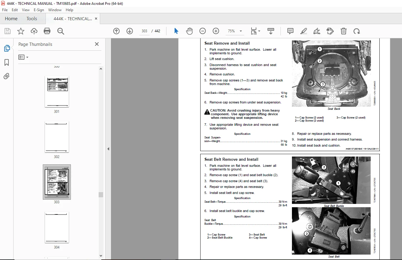
Seat and Seat Belt303
Seat Remove and Install303
Seat Belt Remove and Install303
Heating and Air Conditioning305
Proper Refrigerant Handling305
R134a Refrigerant Cautions305
R134a Compressor Oil Charge Check305
R134a Compressor Oil Removal305
R134a Component Oil Charge306
Refrigerant Leak Testing306
Refrigerant Hoses and Tubing Inspection307
R134a Refrigerant Recovery/Recycling and Charging Station Instal307
R134a System Recover308
R134a System Evacuate309
R134a System Charge310
Air Conditioner System Cleaning Procedures311
Air Conditioner System Purge311
Air Conditioner System Flush312
Air Conditioning Module With Heater/Evaporator Coil314
Heater/Evaporator Coil Remove and Install315
Expansion Valve Remove and Install316
Freeze Control Switch Remove and Install316
Freeze Control Switch Bench Test317
Heater Control Valve Remove and Install317
Heater Control Valve Leak Check317
Blower Motor Assembly Remove and Install318
Receiver-Dryer Remove and Install318
Condenser Remove and Install319
Air Conditioning High-Low Pressure Switch Remove and Install319
Fresh Air Filter Remove and Install320
Recirculating Air Filter Remove and Install321
Compressor Remove and Install322
Compressor Clutch—R134a Disassemble and Assemble323
Clutch Hub Clearance—R134a Check324
Sheet Metal and Styling325
Hood or Engine Enclosure327
Hood Remove and Install327
Engine Side Shields Remove and Install328
Loader331
Bucket333
Bucket Remove and Install333
Powerllel Pin-On Bucket Remove and Install334
Welded Bucket Cutting Edges Remove and Install335
Bolt-On Cutting Edges Remove and Install336
Cracked Cutting Edge Repair336
Frames337
Loader Bucket Tilt Linkage Remove and Install337
Bucket Linkage Seals and Bushings Remove and Install338
Loader Boom Bushings and Seals Remove and Install339
Boom Remove and Install340
Powerllel™ Leveling Link Disassemble and Assemble342
Powerllel™ Bellcrank Remove and Install346
Powerllel™ Bucket Cylinder Remove and Install350
Powerllel™ Bucket Link Disassemble and Assemble356
Powerllel™ Guide Links Remove and Install360
Powerllel™ Coupler Disassemble and Assemble364
Powerllel™ Loader Boom Disassemble and Assemble368
Hi-Vis Coupler Disassemble and Assemble374
Hydraulic System377
General Oil Cleanup Procedure377
Hydraulic Component Failure Cleanup Procedure379
Follow-Up Oil Cleanup Procedure381
Main Hydraulic Pump Remove and Install381
Main Hydraulic Pump Disassemble and Assemble384
Loader Control Valve Remove and Install385
Loader Control Valve Disassemble and Assemble387
Boom Section Disassemble and Assemble388
Bucket Section Disassemble and Assemble389
Auxiliary Section Disassemble and Assemble390
Main Relief Valve Disassemble and Assemble391
Load Sense Relief Valve Disassemble and Assemble391
Circuit Relief With Anticavitation Valve Disassemble and Assembl392
Anticavitation Valve Disassemble and Assemble393
Boom Cylinder Remove and Install394
Bucket Cylinder Remove and Install396
Boom and Bucket Cylinder Disassemble and Assemble397
Boom or Bucket Cylinder Bushings and Seals Remove and Install397
Loader Start-Up Procedure398
Hydraulic Reservoir Remove and Install398
Pilot Control Valve Remove and Install400
Pilot Control Valve Disassemble and Assemble402
Auxiliary Function Pilot Control Valve Remove and Install404
Auxiliary Function Pilot Control Valve Disassemble and Assemble407
Pilot Accumulator Remove and Install409
Hydraulic Pump Manifold Remove and Install410
Hydraulic Pump Manifold Disassemble and Assemble412
Ride Control Valve Remove and Install414
Ride Control Valve Disassemble and Assemble416
Pin Disconnect Valve Remove and Install417
Pin Disconnect Valve Disassemble and Assemble418
Hydraulic Fan Pump and Axle Circulation Pump Remove and Install419
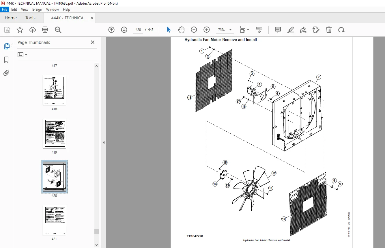
Hydraulic Fan Motor Remove and Install420
Reversing Fan Valve Remove and Install422
Reversing Fan Valve Disassemble and Assemble423
Dealer Fabricated Tools425
Dealer Fabricated Tools427
DFT1132 Hydraulic Pump Removal And Installation Tool427
DFT1273 Axle Planetary Pinion/Service Brake Housing Lifting Brac428
DFT1274 Axle Planetary Pinion/Service Brake Housing Mounting Fix430
DFT1275 Planetary Pinion Carrier Lifting Bracket432
Page Number 3
Section 00 5
Group 0001 7
Section 01 21
Group 0110 23
Section 02 25
Group 0200 27
Group 0225 38
Group 0250 41
Group 0260 93
Section 03 97
Group 0300 99
Group 0350101
Group 0360165
Section 04191
Group 0400193
Section 05199
Group 0505201
Group 0510205
Group 0520215
Group 0530219
Group 0560221
Section 07227
Group 0752229
Section 09231
Group 0960233
Section 10245
Group 1011246
Group 1060263
Section 11265
Group 1111267
Group 1160275
Section 17277
Group 1740279
Group 1746287
Group 1749289
Section 18291
Group 1800293
Group 1810297
Group 1821303
Group 1830305
Section 19325
Group 1910327
Section 31331
Group 3102333
Group 3140337
Group 3160377
Section 99425
Group 9900427
DESCRIPTION:
John Deere 444K Loader Repair Technical Manual TM10685 03MAR11 – PDF DOWNLOAD
- Foreword :
- This manual is written for an experienced technician. Essential tools required in performing certain service work are identified in this manual and are recommended for use. Live with safety: Read the safety messages in the introduction of this manual and the cautions presented throughout the text of the manual. This is the safetyalert symbol. When you see this symbol on the machine or in this manual, be alert to the potential for personal injury. Technical manuals are divided in two parts: repair and operation and tests. Repair sections tell how to repair the components.
- Operation and tests sections help you identify the majority of routine failures quickly. Information is organized in groups for the various components requiring service instruction. At the beginning of each group are summary listings of all applicable essential tools, service equipment and tools, other materials needed to do the job, service parts kits, specifications, wear tolerances, and torque values. Technical Manuals are concise guides for specific machines.
- They are on the job guides containing only the vital information needed for diagnosis, analysis, testing, and repair. Fundamental service information is available from other sources covering basic theory of operation, fundamentals of troubleshooting, general maintenance, and basic type of failures and their causes.
G.B 06/01/25