Technical Repair Manual for John Deere 450DLC Excavator PDF
$29.95
John Deere 450DLC Excavator Repair TECHNICAL MANUAL TM2362 – PDF DOWNLOAD
Description
John Deere 450DLC Excavator Repair TECHNICAL MANUAL TM2362 – PDF DOWNLOAD
FILE DETAILS:
John Deere 450DLC Excavator Repair TECHNICAL MANUAL TM2362 – PDF DOWNLOAD
Language : English
Pages :454
Downloadable : Yes
File Type : PDF
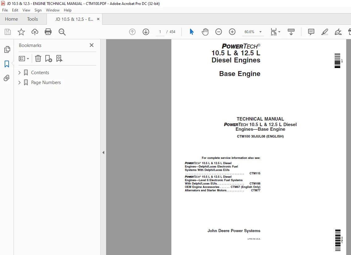
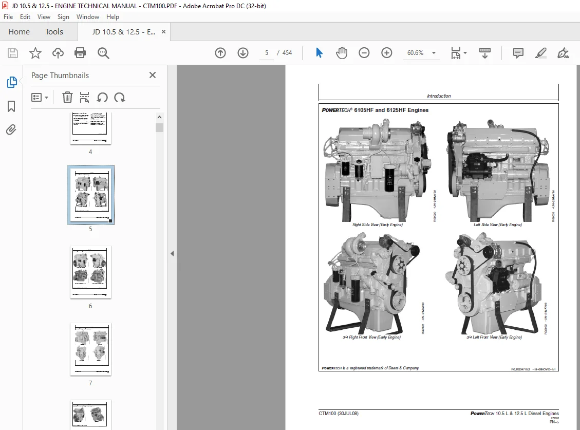
IMAGES PREVIEW OF THE MANUAL:
DESCRIPTION:
John Deere 450DLC Excavator Repair TECHNICAL MANUAL TM2362 – PDF DOWNLOAD
Forward
- This manual is written for an experienced technician. Essential tools required in performing certain service work are identified in this manual and are recommended for use. This manual (CTM100) covers only the base engine. It is one of three volumes on 10.5 L and 12.5 L engines. The following two companion manuals cover electronic fuel system repair, operation and diagnostics: • CTM115—Delphi/Lucas Electronic Fuel Systems With Delphi/Lucas EUIs • CTM188—Level 6 Electronic Fuel Systems With Delphi/Lucas EUIs CTM115 and CTM188 will cover fuel system repair, formerly included in CTM100, Groups 35 and 36. Other manuals will be added in the future to provide added information on new electronic fuel systems. A complete set of all three manuals covering the 10.5 L and 12.5 L engines can be procured by ordering CTM650 Binder Set. Live with safety:
- Read the safety messages in the introduction of this manual and the cautions presented throughout the text of the manual. This is the safety-alert symbol. When you see this symbol on the machine or in this manual, be alert to the potential for personal injury. Use this component technical manual in conjunction with the machine technical manual. An application listing in Section 01, Group 001 identifies product-model/component type-model relationship. Information is organized in sections and groups for the various components requiring service instruction. At the end of this manual are summary listings of all applicable essential tools, service equipment and tools, other materials needed to do the job, service parts kits, specifications, wear tolerances, and torque values. Before beginning repair on an engine, clean the engine and mount on a repair stand. (See Section 2, Group 010.) This manual contains SI Metric units of measure followed immediately by the U.S. customary units of measure.
- Most hardware on these engines is metric. Some components of this engine may be serviced without removing the engine from the machine. Refer to the specific machine technical manual for information on this and for engine removal and installation procedures. Read each block of material completely before performing service to check for differences in procedures or specifications. Follow only the procedures that apply to the engine model number you are working on. If only one procedure is given, that procedure applies to all the engines in the manual. CALIFORNIA PROPOSITION 65 WARNING Diesel engine exhaust and some of its constituents are known to the State of California to cause cancer, birth defects and other reproductive harm.
TABLE OF CONTENTS:
John Deere 450DLC Excavator Repair TECHNICAL MANUAL TM2362 – PDF DOWNLOAD
Contents 13
General Information 15
Safety 17
Handle Fluids Safely—Avoid Fires 17
Service Cooling System Safely 17
Prepare for Emergencies 17
Handling Batteries Safely 18
Avoid High-Pressure Fluids 19
Wear Protective Clothing 19
Service Machines Safely 20
Work In Ventilated Area 20
Work in Clean Area 20
Remove Paint Before Welding or Heating 21
Avoid Heating Near Pressurized Fluid Lines 21
Illuminate Work Area Safely 22
Use Proper Lifting Equipment 22
Construct Dealer-Made Tools Safely 22
Practice Safe Maintenance 23
Use Proper Tools 23
Dispose of Waste Properly 24
Live With Safety 24
Engine Identification and Applications 25
Engine Model Designation 25
Engine Serial Number Plate Information 26
Engine Option Code Label 27
Engine Application Chart 28
Fuels, Lubricants and Coolant 31
Diesel Fuel 31
Biodiesel Fuel 32
Lubricity of Diesel Fuel 33
Testing Diesel Fuel 33
Diesel Engine Break-In Oil 34
Diesel Engine Oil—Non-Certified and Tier I Certified Engines 35
Diesel Engine Oil—Tier II Engines 36
Extended Diesel Engine Oil Service Intervals 37
Alternative and Synthetic Lubricants 37
Mixing of Lubricants 38
OILSCAN™ and COOLSCAN™ 38
Grease 39
Diesel Engine Coolant 40
Supplemental Coolant Additives 41
Testing Diesel Engine Coolant 42
Replenishing Supplemental Coolant Additives (SCAs) Between Coolant Changes 43
Operating in Warm Temperature Climates 44
Flush and Service Cooling System 45
Disposing of Coolant 46
Repair and Adjustments 47
Engine Rebuild Guide, Break-In and Tune-Up 51
Engine Overhaul Guidelines 51
Engine Repair Stand 51
Safety Precautions 52
Disconnect Turbocharger Oil Inlet Line 53
Install Engine Adapter Onto Repair Stand 53
Engine Lifting Procedure 54
Mount Engine Onto Repair Stand 56
Clean Engine 57
6105 and 6125 Engine Disassembly Sequence 58
Sealant Application Guidelines 61
6105 and 6125 Engine Assembly Sequence 63
Engine Break-In Guidelines 65
Perform Engine Break-In 66
Check Crankcase Ventilation System 67
Check Air Intake System 68
Check Exhaust System 68
Check and Service Cooling System 69
Check Electrical System 71
Preliminary Engine Testing Before Tune-Up 72
General Tune-Up Recommendations 73
Cylinder Head and Valves 75
Remove and Install Rocker Arm Cover 75
Clean and Inspect Crankcase Ventilation Assembly 76
Replace Rocker Arm Cover Gasket 77
Check and Adjust Valve Assembly Clearances and Injector Preload 78
Remove Rocker Arm Assembly 84
Remove Cylinder Head 86
Diagnosing Head Gasket Joint Failures 91
Head Gasket Inspection and Repair Sequence 93
Disassemble and Inspect Rocker Arms and Shaft Assembly 95
Preliminary Cylinder Head and Valve Checks 96
Assemble Rocker Arms and Shaft Assembly 97
Check Valve Height in Relation to Head Surface (Valve Recess) 97
Remove Valve Assembly 98
Inspect and Measure Valve Springs 99
Inspect Valve Rotators100
Clean, Inspect, and Measure Valves101
Grind Valves102
Clean and Inspect Cylinder Head103
Check Cylinder Head Flatness104
Measure Cylinder Head Thickness105
Resurface Cylinder Head Combustion Face106
Measure Valve Guide ID107
Replace Valve Guides107
Clean and Inspect Valve Seats108
Grind Valve Seats109
Remove Valve Seat Inserts110
Measure Valve Seat Bore in Cylinder Head111
Install Valve Seat Inserts112
Install Valves112
Replace Unit Injector Sleeve in Cylinder Head Using JDG981114
Replace Unit Injector Sleeve in Cylinder Head Using JDG1184119
Remove Unit Injector Sleeve Using JDG10014130
Clean and Inspect Top Deck of Cylinder Block132
Measure Cylinder Liner Standout (Height Above Block)133
Install Cylinder Head134
Torque-Turn Cylinder Head Cap Screws136
Install Rocker Arm Assembly138
Complete Final Assembly for Cylinder Head Installation145
Cylinder Block, Liners, Pistons, and Rods147
Remove and Install Cylinder Block Front Plate147
Preliminary Liner, Piston, and Rod Checks151
Connecting Rods—General Information152
Remove Pistons and Connecting Rods153
Measure Cylinder Liner Standout (Height Above Block)157
Remove Cylinder Liners Using D01062AA or D01073AA Cylinder Liner Puller158
Remove Cylinder Liners Using JDG1145 Cylinder Liner Service Set160
Visually Inspect Cylinder Liners162
Deglaze Cylinder Liners163
Clean Cylinder Liners164
Cylinder Liner Manufacturing Date Code Explanation165
Disassemble Piston/Rod Assembly and Clean Piston166
Check Piston Compression Ring Groove Wear—6105 Engines168
Check Piston Compression Ring Groove Wear—6125 Engines169
Check Piston Oil Control Ring Groove Wear—6105 and 6125 Engines170
Inspect Piston Pin and Pin Bore in Piston171
Determine Piston-to-Liner Clearance172
Measure Liner Flange Thickness174
Inspect and Measure Connecting Rod Bearings175
Inspect Connecting Rod and Cap177
Inspect Piston Pins and Rod Bushings180
Remove Piston Pin Bushing, Clean, and Inspect Bushing Bore182
Install Piston Pin Bushing183
Complete Disassembly of Cylinder Block (If Required)184
Inspect and Clean Cylinder Block186
Measure Cylinder Block188
Recheck Cylinder Liner Standout (Height Above Block)190
Install Cylinder Liner O-Rings and Packings191
Install Cylinder Liners192
Assemble Pistons and Connecting Rods194
Install Pistons and Connecting Rods195
Torque-Turn Connecting Rod Cap Screws199
Check Engine Rotation for Excessive Tightness200
Measure Piston Protrusion200
Remove and Install Piston Spray Jets201
Complete Final Assembly202
Crankshaft, Main Bearings, and Flywheel203
Crankshaft Vibration Damper Torque Sequence203
Inspect Crankshaft Vibration Damper204
Check Crankshaft End Play205
Remove Crankshaft Rubber Damper and Pulley206
Remove Crankshaft Front Oil Seal207
Remove Timing Gear Cover208
Check Flywheel Housing Face Runout209
Check Flywheel Face Flatness210
Remove Flywheel210
Inspect and Repair Flywheel211
Replace Flywheel Ring Gear212
Remove and Install Flywheel Housing213
Install Flywheel214
Remove Rear Crankshaft Oil Seal and Housing Assembly215
Crankshaft and Main Bearing Failure Analysis218
Remove Crankshaft Main Bearings219
Check Main Bearing-to-Journal Oil Clearance221
Remove Crankshaft222
Inspect Crankshaft223
Measure Assembled ID of Bearings and OD of Crankshaft Journals225
Measure Assembled ID of Main Bearing Caps (Without Bearings)226
Crankshaft Grinding Guidelines227
Crankshaft Grinding Specifications228
Replace Crankshaft Drive Gear229
Inspect Thrust Bearings230
Thrust Bearing New Part Specifications230
Install Main Bearing Inserts in Block231
Install Crankshaft232
Install Crankshaft Rear Oil Seal Housing235
Install Crankshaft Rear Oil Seal and Wear Sleeve Assembly236
Install Timing Gear Cover237
Install Crankshaft Vibration Damper and Front Oil Seal242
Complete Final Assembly246
Camshaft and Timing Gear Train247
Camshaft Gear Access Cover Torque Sequence247
Check and Adjust Camshaft-to-Crankshaft Timing248
Adjust Front Timing Gear Backlash250
Remove and Install Camshaft255
Replace Fuel Supply Pump Drive Pin264
Visually Inspect Camshaft and Roller Followers264
Inspect and Measure Camshaft Bushing ID and Journal OD265
Measure Camshaft Lobe Lift Height266
Inspect Camshaft Position Sensor Lobe266
Replace Camshaft Bushings267
SAE “A” (Front) and SAE “B” (Rear) Auxiliary Drive Assembly272
SAE “B” Rear Auxiliary Drive273
Align SAE “A” Front Auxiliary Drive Adapter274
Lubrication System275
Oil Filter and Oil Conditioning Housing Assembly275
Remove Oil Filter and Valve Housing/Oil Cooler Cover and Valve Housing276
Inspect and Replace Oil Filter Adapter276
Remove, Inspect, and Install Oil Pressure Regulating Valve277
Remove, Inspect, and Install Oil Cooler and Oil Filter Bypass Valves278
Remove, Inspect, and Install Oil Pressure Relief Valve (If Equipped)279
Remove, Clean, and Inspect Engine Oil Cooler280
Install Oil Cooler/Oil Filter Valve Housing Assembly or Oil Cooler Cover/Valve Housing Assembly282
Remove Engine Oil Pump284
Clean and Inspect Oil Pump and Drive Gear285
Install Engine Oil Pump286
Remove Engine Oil Pan287
Remove and Install Oil Pickup Tube288
Install Engine Oil Pan289
Cooling System291
Replace Bearings in Fan Drive Assembly291
Inspect and Check Belt Tensioner Spring Tension295
Replace Belt Tensioner Assembly297
Remove Coolant Pump298
Clean and Inspect Coolant Pump Parts299
Install Coolant Pump300
Remove Thermostats301
Install Thermostats302
Test Thermostat Opening Temperature303
Remove and Install Thermostat Housing304
Remove and Install Coolant Heater—if Equipped305
Air Intake and Exhaust System307
Extending Turbocharger Life307
Remove Turbocharger309
Turbocharger Failure Analysis310
Turbocharger Seven-Step Inspection312
Perform Radial Bearing Clearance Test319
Perform Axial Bearing End Play Test320
Repair Turbocharger320
Prelube Turbocharger321
Install Turbocharger322
Turbocharger Break-In323
Remove, Inspect, and Install Exhaust Manifold324
Remove, Inspect, and Install Intake Manifold327
Remove and Install Aftercooler Assembly (6105A and 6125A Engines)329
Inspect and Repair Aftercooler (6105A and 6125A Engines)331
Fuel System333
Fuel System333
Starting and Charging Systems335
Remove and Install Alternator (OEM Engines)335
Remove and Install Starter Motor (OEM Engines)336
Theory of Operation337
Base Engine Operation339
General Engine Operation339
Lubrication System Operation342
Cooling System Operation346
Fuel System Theory of Operation348
Head Gasket Joint Construction and Operation349
Intake and Exhaust System Operation350
Turbocharger Operation351
How the Turbocharger is Lubricated352
Diagnostics353
Observable Diagnostics and Tests355
About this Section of the Manual355
105L/125L – L1 – Excessive Oil Consumption356
105L/125L – L1 – Excessive Oil Consumption356
356
357
357
358
105L/125L – L2 Engine Oil Pressure High359
105L/125L Engines – L3 – Engine Oil Pressure Low360
105L/125L Engines – L4 – Fuel in Oil361
105L/125L – C1 – Engine Coolant Temperature Above Normal362
105L/125L – C2 – Engine Coolant Temperature Below Normal363
105L/125L Engines – C3 – Coolant in Oil or Oil in Coolant363
Dynamometer Test364
Engine Oil Consumption365
Check Engine Oil Pressure366
Check for Excessive Engine Crankcase Pressure (Blow-By)367
Check for Turbocharger Oil Seal Leak369
Inspect Thermostat and Test Opening Temperature370
Pressure Test Cooling System and Radiator Cap371
Check for Head Gasket Failures373
Check Intake Manifold Pressure (Turbo Boost)375
Check for Intake and Exhaust Restrictions376
Check for Intake Air Leaks377
Check for Exhaust Air Leaks378
Check Camshaft-to-Crankshaft Timing379
Check Crankshaft Position Sensor Depth380
Tools and Other Materials381
Repair Tools and Other Materials383
Engine Rebuild Guide, Break-In and Tune-Up (Group 010) Other Material383
Cylinder Head and Valves (Group 020) Essential Tools383
Cylinder Head and Valves (Group 020) Service Equipment and Tools388
Cylinder Head and Valves (Group 020) Other Material389
Cylinder Block, Liners, Pistons, and Rods (Group 030) Essential Tools390
Cylinder Block, Liners, Pistons, and Rods (Group 030) Service Equipment and Tools395
Cylinder Block, Liners, Pistons, and Rods (Group 030) Other Material396
Crankshaft, Main Bearings and Flywheel (Group 040) Essential Tools397
Crankshaft, Main Bearings and Flywheel (Group 040) Service Equipment and Tools399
Crankshaft, Main Bearings and Flywheel (Group 040) Other Material400
Camshaft and Timing Gear Train (Group 050) Essential Tools401
Camshaft and Timing Gear Train (Group 050) Service Equipment and Tools403
Camshaft and Timing Gear Train (Group 050) Other Material404
Lubrication System (Group 060) Essential Tools405
Lubrication System (Group 060) Other Material406
Cooling System (Group 070) Essential Tools407
Cooling System (Group 070) Other Material407
Air Intake and Exhaust System (Group 080) Essential Tools408
Air Intake and Exhaust System (Group 080) Other Material408
Starting and Charging Systems (Group 100) Essential Tools409
Diagnostic Service Tools411
Observable Diagnostics and Tests Essential Tools411
Dealer Fabricated Service Tools413
How to Make Tools413
DFRG4—Camshaft Locking Tool413
DFRG3—Cylinder Liner Holding Fixture414
Specifications415
Repair and General OEM Specifications417
General OEM Engine Specifications417
Unified Inch Bolt and Screw Torque Values418
Metric Bolt and Screw Torque Values419
Engine Rebuild Guide, Break-In and Tune-Up (Group 010) Specifications420
Cylinder Head and Valves (Group 020) Specifications421
Cylinder Block, Liners, Pistons and Rods (Group 030) Specifications425
Crankshaft, Main Bearings and Flywheel (Group 040) Specifications430
Camshaft and Timing Gear Train (Group 050) Specifications433
Lubrication System (Group 060) Specifications435
Cooling System (Group 070) Specifications437
Air Intake and Exhaust System (Group 080) Specifications439
Starting and Charging Systems (Group 100) Specifications440
Diagnostic Specifications441
Observable Diagnostics and Test Specifications441
Dynamometer Test Specifications (OEM Engines)442
Intake Manifold Pressure (Turbocharger Boost) Specifications444
Page Numbers 13
Section 01 15
Group 000 17
S.M 8/1/25