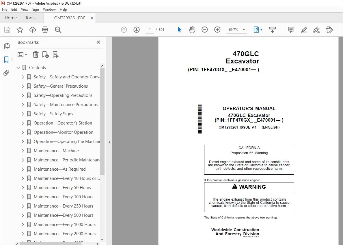
John Deere 470GLC Excavator Operator’s Manual OMT293261 – PDF DOWNLOAD
$28.95
John Deere 470GLC Excavator Operator’s Manual OMT293261 – PDF DOWNLOAD
Description
John Deere 470GLC Excavator Operator’s Manual OMT293261 – PDF DOWNLOAD
- Part Number (P/N): OMT293261_34
- Language: English
- Division: Construction
- Product Lines: Excavators
- Publication Type: Operator’s Manuals
- Associated Model: 470GLC
- Serial Number Range: 1FF470GX_ _E470001
TABLE OF CONTENTS:
John Deere 470GLC Excavator Operator’s Manual OMT293261 – PDF DOWNLOAD
Contents 13
Safety—Safety and Operator Conveniences 17
Safety and Operator Convenience Features 17
Safety—General Precautions 18
Recognize Safety Information 18
Follow Safety Instructions 18
Operate Only If Qualified 18
Wear Protective Equipment 19
Avoid Unauthorized Machine Modifications 19
Add Cab Guarding for Special Uses 19
Inspect Machine 20
Stay Clear of Moving Parts 20
Avoid High-Pressure Fluids 20
Avoid High-Pressure Oils 21
Work In Ventilated Area 21
Avoid Static Electricity Risk When Refueling 22
Prevent Fires, Clean Debris From Machine 23
In Case of Machine Fire 23
Prevent Battery Explosions 24
Handle Chemical Products Safely 24
Handle Starting Fluid Safely 24
Decommissioning — Proper Recycling and Disposal of Fluids and Components 25
Exhaust Filter Ash Handling and Disposal 25
Prepare for Emergencies 25
Clean Debris from Machine 26
Safety—Operating Precautions 27
Use Steps and Handholds Correctly 27
Start Only From Operator’s Seat 27
Use and Maintain Seat Belt 27
Prevent Unintended Machine Movement 28
Avoid Work Site Hazards 28
Keep Riders Off Machine 29
Avoid Backover Accidents 29
Inspect and Maintain ROPS 29
Travel Safely 30
Prevent Acid Burns 30
Avoid Machine Tip Over and Machine Damage 31
Use Special Care When Lifting Objects 31
Add and Operate Attachments Safely 31
Safety—Maintenance Precautions 32
Park and Prepare for Service Safely 32
Service Cooling System Safely 32
Remove Paint Before Welding or Heating 33
Make Welding Repairs Safely 33
Drive Metal Pins Safely 33
Clean Exhaust Filter Safely 34
Safety—Safety Signs 35
Safety Signs 35
Hydraulic Coupler Safety Signs—If Equipped 36
Operation—Operator’s Station 37
Pedals, Levers, and Panels 37
Switch Panel 38
Switch Panel Functions 39
Rear Left Panel 40
Horn 40
Power Boost Button 41
Pilot Shutoff Lever 41
Engine Stop Switch 42
Left Console 42
Travel Alarm and Travel Alarm Cancel Switch 42
Seat Heater Switch 43
Boom Mode Switch 43
Reversing Fan Switch 44
Counterweight Removal or Install Switch—If Equipped 45
Rear Light Switch—If Equipped 45
Right Console 46
Exhaust Filter Parked Cleaning Switch 46
Right Enable Switch—If Equipped 47
Cab Heater and Air Conditioner 48
Selecting Display Between Celsius and Fahrenheit 49
Operating the AM/FM Radio 50
Fire Extinguisher Mounting Location 51
Secondary Exit Tool 51
Cab Dome Light Switch 52
Opening Upper Front (Secondary Exit) Window 52
Removing and Storing the Lower Front Window 53
Opening Cab Door Window 53
Opening and Closing the Polycarbonate Type Roof Exit Cover 54
Adjusting the Mechanical Suspension Seat 54
Adjusting the Air Suspension Seat—If Equipped 55
Adjusting Pilot Control Lever Console Height 55
Operation—Monitor Operation 56
Monitor 56
Monitor Functions 57
Monitor Start-Up 58
Main Menu 59
Main Menu—Alarm List 60
Main Menu—Air Conditioner 65
Main Menu—Radio 67
Main Menu—Work Mode 68
Main Menu—Setting Menu 69
Main Menu—Setting Menu—Date and Time 70
Main Menu—Setting Menu—Attachment Name Input 70
Main Menu—Setting Menu—Auto-Shutdown 71
Main Menu—Setting Menu—Auto Exhaust Filter Cleaning 72
Main Menu—Setting Menu—Sub Meter Selection 73
Main Menu—Setting Menu—Rear View Camera Monitor 74
Main Menu—Setting Menu—Display Item Selection 75
Main Menu—Setting Menu—Brightness Adjustment 75
Main Menu—Setting Menu—Language 75
Main Menu—Setting Menu—Unit Selection 76
Main Menu—Setting Menu—Main Menu Sequence Change 76
Main Menu—Information Menu 77
Main Menu—Information Menu—Operation 78
Main Menu—Information Menu—Maintenance 79
Main Menu—Information Menu—Troubleshooting 79
Main Menu—Information Menu—Monitoring 80
Operation—Operating the Machine 81
Before Starting Work 81
Operator’s Daily Machine Check Before Starting 81
Starting Engine 82
Cold Weather Start Aid 83
Cold Weather Warmup 84
Operate Within Machine Limits 85
Digging and Grading Operation 86
Travel Pedals and Levers 87
Exhaust Filter 88
Exhaust Filter Parked Cleaning 90
Control Lever Pattern Operation 92
Control Lever Pattern Conversion 93
Operating in Water and Mud 94
Driving Up a Steep or Slippery Slope 94
Lifting 95
Towing Machine 95
Lower Boom With Engine Stopped 96
Parking the Machine 97
Lifting the Machine 98
Counterweight Removal With Hydraulic Removal Option—If Equipped 99
Counterweight Installation With Hydraulic Removal Option—If Equipped 105
Locking the Hydraulic Coupler to the Attachment—If Equipped 111
Unlocking the Hydraulic Coupler From the Attachment—If Equipped 113
Maintenance—Machine 115
Required Emission-Related Information 115
Diesel Fuel 115
Diesel Fuel Specifications 115
Lubricity of Diesel Fuel 116
Handling and Storing Diesel Fuel 116
Biodiesel Fuel 117
Testing Diesel Fuel 117
Supplemental Diesel Fuel Additives 118
Fuel Filters 118
Minimizing the Effect of Cold Weather on Diesel Engines 119
Alternative and Synthetic Lubricants 119
Mixing of Lubricants 120
Lubricant Storage 120
Diesel Engine Oil — Interim Tier 4, Final Tier 4, Stage IIIB, Stage IV, and Stage V 120
Engine Oil and Filter Service Intervals — Interim Tier 4, Final Tier 4, Stage IIIB, Stage IV, and Stage V Engines 121
Oil Filters 121
Hydraulic Oil 122
Swing Gear Case and Travel Gear Case Oils 123
Track Adjuster, Working Tool Pivot, Swing Bearing, and Swing Bearing Gear Grease 123
Diesel Engine Coolant (engine without wet sleeve cylinder liners) 124
Water Quality for Mixing with Coolant Concentrate 125
Drain Intervals for Diesel Engine Coolant 125
John Deere COOL-GARD™ II Coolant Extender 126
Supplemental Coolant Additives 126
Operating in Warm Temperature Climates 126
Testing Coolant Freeze Point 127
Disposing of Coolant 127
Maintenance—Periodic Maintenance 128
Service Machine at Specified Intervals 128
Check the Hour Meter Regularly 128
Prepare Machine for Maintenance 129
Open Engine Cover for Service 130
Open Access Doors for Service 130
Fuel Tank 131
Hydraulic Breaker Attachment 131
Fluid Analysis Program Test Kits and 3-Way Coolant Test Kit 131
Service Intervals 132
Required Parts 134
Maintenance—As Required 136
Drain Fuel Tank Sump 136
Remove and Clean Fuel Tank Inlet Screen 136
Clean Radiator Air Inlet Screen 137
Check and Adjust V-Belts 139
Clean Rear Camera Lens 140
Check and Clean Air Cleaner Dust Unloader Valve 140
Drain Primary Fuel Filter and Water Separators 141
Drain Final Fuel Filter and Water Separators 141
Check Windshield Washer Fluid Level 142
Check and Adjust Track Sag 142
Check Coolant 144
Clean and Tighten Battery Terminals 144
Maintenance—Every 10 Hours or Daily 145
Check Coolant Level in Recovery Tank 145
Check Engine Oil Level 147
Check Hydraulic Oil Level 149
Lubricate Working Tool Pivots and Links 150
Lubricate Hydraulic Coupler—If Equipped 150
Maintenance—Every 50 Hours 151
Lubricate Front End Pin Joints 151
Maintenance—Every 100 Hours 152
Inspect and Re-Torque Track Hardware 152
Maintenance—Every 250 Hours 153
Check Hybrid Battery Electrolyte Level—If Equipped 153
Check Swing Gear Case Oil Level 155
Check Travel Gear Case Oil Level 155
Drain Hydraulic Tank Sump 156
Take Engine Oil Sample 156
Maintenance—Every 500 Hours 157
Lubricate Swing Bearing Gear 157
Drain and Refill Engine Oil and Replace Filters 158
Check Air Intake Hoses 159
Replace Primary Fuel Filter and Water Separators 159
Replace Final Fuel Filter and Water Separators 160
Lubricate Swing Bearing 160
Clean Cab Fresh Air and Cab Recirculating Air Filters 161
Take Fluid Samples 161
Maintenance—Every 1000 Hours 162
Drain and Refill Swing Gear Case Oil 162
Check Coolant 162
Replace Air Conditioner V-Belt 163
Adjust Engine Valve Lash 163
Replace Air Cleaner Elements 164
Replace Pilot System Oil Filter 165
Replace Hydraulic Tank Cap Breather Element 166
Replace Hydraulic Tank Oil Filter 167
Replace Pump Case Drain Filter 168
Maintenance—Every 2000 Hours 169
Drain and Refill Travel Gear Case Oil 169
Maintenance—Every 4000 Hours 170
Drain and Refill Hydraulic Tank Oil and Clean Suction Screen 170
Drain Cooling System 172
Cooling System Fill and Deaeration Procedure 173
Maintenance—Every 4500 Hours 174
Service Exhaust Filter 174
Miscellaneous—Machine 175
Bleed Fuel System 175
Bleed Air From Hydraulic System 176
Do Not Service or Adjust Injection Nozzles or High-Pressure Fuel Pump 176
Do Not Service Control Valves, Cylinders, Pumps, or Motors 176
Precautions for Alternator and Regulator 177
Using Booster Batteries—24-Volt System 177
Handling, Checking, and Servicing Batteries Carefully 178
Using Battery Charger 179
Replacing Batteries 181
Welding on Machine 181
Keep Electronic Control Unit Connectors Clean 182
Clean the Machine Regularly 182
Adding 12-Volt Accessories 182
JDLink Machine Monitoring System (MMS)—If Equipped 182
Replacing Fuses 183
Replacing Bucket Teeth 185
Replacing Bucket Tooth Tip—Heavy-Duty Bucket 186
Replacing Bucket Teeth—TK Series 186
Bucket Remove and Install 187
Track Sag General Information 191
Check Track Shoe Hardware 191
Hardware Torque Specifications 191
Unified Inch Bolt and Screw Torque Values 192
Metric Bolt and Screw Torque Values 193
Miscellaneous—Transporting 194
Transporting the Machine by Trailer 194
Types of Packings for Transportation 195
Packing Dimensions and Weights for Transportation 196
Retracting or Extending the Side Frame 199
Retracting the Side Frame 200
Extending the Side Frame 201
Miscellaneous—Machine Assembly 204
Precautions for Assembling 204
Precautions for Lifting Work 204
Precautions for Operating Machine 204
Avoid High-Pressure Fluids 204
Installation Sequence 205
Installing Boom Cylinders 205
Installing Boom 208
Connecting Hoses Between Boom and Machine 209
Connecting Boom Cylinder Rod 211
Installing Arm 212
Connecting Arm Cylinder Rod 213
Connecting Bucket Cylinder Hoses 214
Installing Bucket 215
Lubricate Working Tool Pivots and Links 215
Extending the Side Frame 215
Checking Hydraulic Oil Level 215
Installing Counterweight (With Hydraulic Removal Option) 216
Installing Counterweight (Without Hydraulic Removal Option) 216
Miscellaneous—Operational Checkout 217
Operational Checkout 217
Diagnostic Trouble Code Check 217
Operational Checks—Key Switch Off, Engine Off Checks 217
Operational Checks—Key Switch On, Engine Off Checks 220
Operational Checks—Key Switch On, Engine On Checks 229
Miscellaneous—Troubleshooting 257
Troubleshooting Procedure 257
Engine 258
Electrical System 262
Hydraulic System 264
Hydraulic Counterweight 266
Miscellaneous—Storage 267
Prepare Machine for Storage 267
Monthly Storage Procedure 267
Miscellaneous—Machine Numbers 269
Record Product Identification Number (PIN) 269
Record Engine Serial Number 269
Record Travel Motor Serial Numbers 269
Record Swing Motor Serial Numbers 270
Hydraulic Pump Serial Number 270
Record Hydraulic Coupler Serial Number—If Equipped 270
Keep Proof of Ownership 270
Keep Machines Secure 271
Miscellaneous—Specifications 272
Engine Specifications 272
Drain and Refill Capacities 272
Machine Specifications 273
Working Ranges 275
Lift Capacity—Arm: 2 9 m (9 ft 6 in ); Bucket: 2 3 m³ (3 0 yd³); Shoe: 750 mm (30 in ) 278
Lift Capacity—Arm: 3 4 m (11 ft 2 in ); Bucket: 2 1 m³ (2 7 yd³); Shoe: 750 mm (30 in ) 279
Lift Capacity—Arm: 3 9 m (12 ft 10 in ); Bucket: 1 9 m³ (2 5 yd³); Shoe: 750 mm (30 in ) 281
Lift Capacity—Arm: 4 9 m (16 ft 1 in ); Bucket: 1 4 m³ (1 8 yd³); Shoe: 750 mm (30 in ) 283
Lift Capacity—BE-Arm: 2 9 m (9 ft 6 in ); Bucket: 2 5 m³ (3 3 yd³); Shoe: 750 mm (30 in ) 284
Lift Capacity—Arm: 2 9 m (9 ft 6 in ); Bucket: 2 3 m³ (3 0 yd³); Shoe: 900 mm (36 in ) 285
Lift Capacity—Arm: 3 4 m (11 ft 2 in ); Bucket: 2 1 m³ (2 7 yd³); Shoe: 900 mm (36 in ) 286
Lift Capacity—Arm: 3 9 m (12 ft 10 in ); Bucket: 1 9 m³ (2 5 yd³); Shoe: 900 mm (36 in ) 288
Lift Capacity—Arm: 4 9 m (16 ft 1 in ); Bucket: 1 4 m³ (1 8 yd³); Shoe: 900 mm (36 in ) 290
Lift Capacity—BE-Arm: 2 9 m (9 ft 6 in ); Bucket: 2 5 m³ (3 3 yd³); Shoe: 900 mm (36 in ) 291
Page Number 13
Section 1-1 17
Section 1-2 18
Section 1-3 27
Section 1-4 32
Section 1-5 35
Section 2-1 37
Section 2-2 56
Section 2-3 81
Section 3-1 115
Section 3-2 128
Section 3-3 136
Section 3-4 145
Section 3-5 151
Section 3-6 152
Section 3-7 153
Section 3-8 157
Section 3-9 162
Section 3-10 169
Section 3-11 170
Section 3-12 174
Section 4-1 175
Section 4-2 194
Section 4-3 204
Section 4-4 217
Section 4-5 257
Section 4-6 267
Section 4-7 269
Section 4-8 272
S.V 04/24