Trusted Business
Verified & Licensed
Virus Free Files
100% Safe Downloads
Secure Payment
SSL Protected
Instant Delivery
Available Immediately
John Deere 544G,544G LL,544G TC,624G,and 644G Loader Repair Technical Manual PDF
$30.95
John Deere 544G,544G LL,544G TC,624G,and 644G Loader Repair Technical Manual TM1530 – PDF DOWNLOAD
Instant PDF Download
Available immediately
Save to Your Device
Download & keep forever
Antivirus Scanned
100% virus-free
Trusted Worldwide
175,000+ customers
Description
John Deere 544G,544G LL,544G TC,624G,and 644G Loader Repair Technical Manual TM1530 – PDF DOWNLOAD
FILE DETAILS:
John Deere 544G,544G LL,544G TC,624G,and 644G Loader Repair Technical Manual TM1530 – PDF DOWNLOAD
Language : English
Pages : 580
Downloadable : Yes
File Type : PDF
IMAGES PREVIEW OF THE MANUAL:
TABLE OF CONTENTS:
John Deere 544G,544G LL,544G TC,624G,and 644G Loader Repair Technical Manual TM1530 – PDF DOWNLOAD
Contents 5
General Information 9
Safety Information 11
Handle Fluids Safely—Avoid Fires 11
Prevent Battery Explosions 11
Prepare for Emergencies 11
Prevent Acid Burns 12
Handle Chemical Products Safely 13
Avoid High-Pressure Fluids 13
Park Machine Safely 14
Support Machine Properly 14
Wear Protective Clothing 14
Work in Clean Area 15
Service Machines Safely 15
Work In Ventilated Area 15
Illuminate Work Area Safely 15
Replace Safety Signs 16
Use Proper Lifting Equipment 16
Remove Paint Before Welding or Heating 16
Avoid Heating Near Pressurized Fluid Lines 17
Keep ROPS Installed Properly 17
Service Tires Safely 18
Avoid Harmful Asbestos Dust 18
Practice Safe Maintenance 19
Use Proper Tools 19
Dispose of Waste Properly 20
Live With Safety 20
General Specifications 22
544G Specifications 22
544G Drain And Refill Capacities 24
544G LL Specifications 25
544G LL Drain And Refill Capacities 27
544G TC Specifications 28
544G TC Drain And Refill Capacities 30
624G Specifications 31
624G Drain And Refill Capacities 33
644G Specifications 34
644G Drain And Refill Capacities 36
Torque Values 37
Hardware Torque Specifications 37
ROPS Torque Specifications 37
Metric Bolt and Cap Screw Torque Values 38
Additional Metric Cap Screw Torque Values 39
Unified Inch Bolt and Cap Screw Torque Values 41
Check Oil Lines And Fittings 42
Service Recommendations for O-Ring Boss Fittings 43
Service Recommendations for Flat Face O-Ring Seal Fittings 45
Service Recommendations for Metric Series Four Bolt Flange Fitting 46
Service Recommendations For Inch Series Four Bolt Flange Fittings 47
Fuels And Lubricants 49
Fuel Specifications 49
Storing Fuel 49
Do Not Use Galvanized Containers 50
Fuel Tank 50
Engine Oil 51
Hydraulic System Oil And Differential Oil 52
Transmission Oil 53
Grease 54
Alternative and Synthetic Lubricants 55
Lubricant Storage 55
Mixing of Lubricants 56
Diesel Engine Coolant 57
Inspection Procedures 59
Planned Inspection Program I (PIP I) 59
Planned Inspection Program II (PIP II) 59
Using The Checklists 60
Delivery Service 60
John Deere 544G, 624G And 644G Loader 61
John Deere 544G, 624G, And 644G Loader 64
Wheels 67
Powered Wheels And Fastenings 69
Other Material 69
Specifications 69
Remove Tire 70
Install Tire 71
544G And 544G TC 72
544G LL 72
624G 73
644G 73
Axles And Suspension Systems 75
Removal And Installation 77
John Deere 1200 And 1400 Series Axles—Use CTM43 77
Other Material 77
Specifications 78
Remove And Install Front Axle And Differential 79
Remove Rear Axle And Differential 82
Install Rear Axle And Differential Assembly 84
Axle Shafts, Bearings And U-Joints 85
Other Material 85
Specifications 85
Disassemble, Inspect, And Assemble Support Bearing And Drive Shaft 86
Remove And Install Rear Differential Drive Line 87
Hydraulic System 89
Specifications 89
Remove And Install Differential Lock Solenoid Valve 89
Transmission 91
Removal And Installation 93
Essential Tools 93
Service Equipment And Tools 93
Specifications 94
Remove And Install Transmission 95
Control Linkage101
Other Material101
Specifications101
Remove And Install Transmission Shift Lever102
Input Drive Shafts And U-Joints103
Specifications103
Remove, Disassemble, Assemble And Install Transmission Drive Shaft103
Gear, Shafts, Bearings And Power Shift Clutch105
Essential Tools105
Service Equipment And Tools106
Other Material108
Specifications109
Install Repair Stand110
Remove And Install Torque Converter112
Remove Clutch Packs113
Remove And Install Forward And First Drive Gears120
Remove And Install Reverse And Second Drive Gears121
Remove And Install Third And Fourth Drive Gears122
Disassemble And Assemble Clutch Packs123
Clutch Packs132
Remove And Install Fourth Gear Idler Gear—624G, 644G132
Fourth Gear Idler Gear Shaft Orifice Sizes134
Install Fourth Gear Idler Gear—544G, 544G LL, 544G TC135
Install Third And Fourth Gear Clutch Pack, Adjust End Play136
Install Second And Reverse, First And Forward Gear Clutch Packs141
Remove And Install Output Flange148
Remove And Install Output Shaft And Seals150
Remove And Install Output Gear And Oil Shields156
Remove And Install Speed Control Magnetic Pickup158
Hydraulic System159
Essential Tools159
Service Equipment And Tools159
Other Material161
Specifications161
Remove Oil Supply Flange And Oil Pump162
Disassemble Oil Supply Flange164
Assemble Oil Supply Flange166
Input Drive Shaft Orifice Sizes167
Disassemble Oil Pump168
Assemble Oil Pump169
Install Oil Pump On Oil Supply Flange172
Install Oil Supply Flange And Oil Pump174
Remove And Install Converter Minimum Pressure Regulator177
Remove And Install Transmission Oil Filter177
Remove And Install Suction Oil Strainer178
Remove Transmission Control Valve179
Repair Transmission Control Valve 544G (SN —542218), 624G (SN —548398), 644G (SN —548302)181
Control Valve W/6th Solenoid—544G (SN 548219—), 624G (SN 548398—), 644G (SN 548303—)183
Install Transmission Control Valve185
Cross Section Of Thermal Bypass Valve186
Disassemble And Assemble Thermal Bypass Valve187
Engine189
Removal And Installation191
John Deere 6059 Engine Repair—Use CTM8191
John Deere 6068 Engine Repair—Use CTM8191
John Deere 6076 Engine Repair—Use CTM42191
John Deere 6081 Engine Repair—Use CTM86191
Special Or Essential Tools192
Service Equipment And Tools193
Other Material193
Specifications194
Disconnect Turbocharger Oil Inlet Line196
Remove And Install Engine197
Remove And Install Oil Pan199
Remove Fuel Injection Pump—544G, 624G200
Install Fuel Injection Pump—544G, 624G201
Remove Fuel Injection Pump—644G203
Install Fuel Injection Pump—644G204
Remove And Install Fuel Filter Check Valve—644G207
Bleed Fuel System—544G, 624G207
Bleed Fuel System—644G208
Remove And Install Turbocharger209
Remove And Install Water Pump—544G, 624G210
Remove And Install Water Pump—644G211
Remove And Install Fan Drive—644G212
Engine Auxiliary Systems213
Cold Weather Starting Aids215
Specifications215
Remove And Install Starting Aid Solenoid And Nozzle215
Remove And Install Engine Coolant Heater216
Cooling System217
Specifications217
Other Material217
Remove And Install Compressor Belt (If Equipped) And Fan Belts — 544G, 624G, 644G (SN —557738)218
Remove And Install Serpentine Belt — 644G (SN 557739—)219
Remove And Install Fan220
Remove And Install Radiator221
Remove And Install Oil Cooler223
Remove And Install Coolant Level Sensor225
Speed Controls227
Other Material227
Specifications227
Remove And Install Speed Control Linkage228
Speed Control Linkage Adjustment230
Fuel Shut-Off Solenoid Adjustment—644G231
Intake System233
Specifications233
Remove And Install Air Filter Elements—544G, 624G233
Tighten Air Cleaner Hose Clamps234
Remove And Install Air Filter Elements—644G234
Test Air Intake System For Leaks235
External Fuel Supply System237
Other Material237
Specifications237
Remove And Install Fuel Tank238
Remove And Install Primary Filter (Water Separator)239
Disassemble And Assemble Primary Filter (Water Separator)240
Bleed Fuel System—544G, 624G241
Bleed Fuel System—644G241
Remove And Install Fuel Shut-Off Solenoid—644G242
Fuel Shut-Off Solenoid Adjustment—644G243
Dampener Drive245
Elements247
Specifications247
Remove And Install Dampener247
Steering System249
Secondary Steering251
Specifications251
Remove And Install Secondary Steering Pump, Motor And Relay (If Equipped)251
Remove And Install Secondary Steering Inlet Manifold (If Equipped)252
Disassemble And Assemble Secondary Steering Inlet Manifold (If Equipped)253
Hydraulic System255
Service Equipment And Tools255
Other Material255
Specifications256
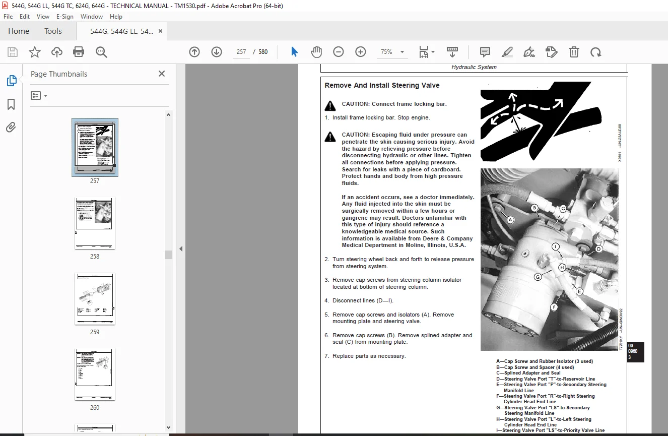
Remove And Install Steering Valve257
Disassemble Steering Valve259
Cross Section Of Steering Valve262
Assemble Steering Valve263
Remove And Install Steering Column266
Remove And Install Steering Cylinders267
Disassemble Steering Cylinder268
Cross Section Of Steering Cylinder271
Assemble Steering Cylinder271
Remove And Install Steering Cylinder Bushings276
Remove And Install Priority Valve277
Cross Section Of Priority Valve278
Disassemble And Assemble Priority Valve279
Service Brakes281
Active Elements283
Essential Tools283
Inspecting Service Brake Pads283
Remove And Install Brake Assembly285
Hydraulic System289
Service Tools And Equipment289
Specifications289
Remove And Install Brake Valve290
Disassemble And Assemble Brake Valve291
Remove And Install Brake Pump292
Disassemble Brake Pump293
Assemble Brake Pump298
Disassemble And Assemble Brake Pump Pressure Compensator303
Remove And Install Brake Accumulator304
Charge Brake Accumulator306
Hydraulic Brake Bleeding Procedure308
Remove And Install Pressure Reducing Valve Manifold309
Park Brake311
Active Elements313
Specifications313
Remove And Install Park Brake Pads314
Disassemble And Assemble Park Brake315
Adjust Park Brake316
Hydraulic System319
Specifications319
Remove And Install Park Brake Release Solenoid Valve320
Remove And Install Park Brake Pressure Switch321
Equipment Attaching323
Drawbar325
Specifications325
Install Counterweight/Drawbar325
Electrical Systems327
Batteries, Support And Cables329
Specifications329
Service Batteries Carefully330
Test Batteries Using Coolant And Battery Tester331
Test Batteries Using High Rate Discharge Test332
Charge Battery332
Remove And Install Batteries333
Remove And Install Battery Disconnect Switch335
Alternator, Regulator And Charging System Wiring337
Motorola 8EM And 8MR Alternator Repair—Use CTM77337
Specifications337
Remove And Install Alternator338
Lighting System339
Specifications339
Replace Halogen Bulbs339
Remove And Install Lights341
Wiring Harness And Switches343
Special Or Essential Tools343
Other Material344
Specifications344
Clutch Cut-Off Switch Adjustment345
Return-To-Dig Adjustment346
Boom Height Kickout Adjustment347
Remove And Install Brake Light Switch348
Remove And Install Brake Low Pressure Switch349
Remove And Install Hydraulic Oil Filter Restriction Switch350
Remove And Install Engine Coolant Level Switch351
Remove And Install Engine Oil Pressure Switch351
Remove And Install Air Filter Restriction Switch352
Remove And Install Transmission Oil Pressure Switch352
Replace DEUTSCH™ Connectors353
Install DEUTSCH™ Contact354
Replace WEATHER PACK™ Connector355
Install WEATHER PACK™ Contact355
Remove Connector Body From Blade Terminals356
Remove Blade Terminals From Fuse Block357
Motors And Actuators359
Starting Motor Repair—Use CTM77359
Special Or Essential Tools359
Specifications359
Remove And Install Starting Motor360
Frame Or Supporting Structure361
Frame Installation363
Specifications363
Welding Repair Of Major Structure364
Separate Engine And Loader Frame365
Remove And Install Upper Pivot Bearing And Seals369
Remove And Install Lower Pivot Bearing And Seals371
Frame Bottom Guards373
Specifications373
Remove And Install Guards374
Chassis Weights375
Specifications375
Remove And Install Counterweights376
Operator’s Station377
Removal And Installation379
Special Or Essential Tools379
Specifications379
Remove And Install Cab Or Canopy380
Operator Enclosure385
Special Or Essential Tools385
Other Material385
Specifications386
Remove And Install Windowpane And Molding387
Remove And Install Windshield Washer388
Remove, Disassemble, Assemble And Install Front Windshield Wiper389
Adjust Front Windshield Wiper390
Remove, Disassemble, Assemble And Install Rear Windshield Wiper391
Remove And Install Defroster Fan—(SN —545144)392
Remove And Install Defroster Fan—(SN 545145—)393
Remove And Install Door Handle And Door/Window Release394
Seat And Seat Belt397
Specifications397
Disassemble And Assemble Seat398
Disassemble And Assemble Seat Belt404
Heating And Air Conditioning405
Special Or Essential Tools405
Service Equipment And Tools410
Other Material410
Service Parts Kits For Compressor411
Specifications412
Proper Refrigerant Handling413
R12 And R134a Refrigerant Cautions413
R12 Component Oil Charge414
R12 Refrigerant Evacuation And Charging Station Installation Procedure415
Recover R12 System416
Evacuate R12 System417
Charge R12 System419
R134a Compressor Oil Information420
R134a Compressor Oil Charge Check420
R134a Compressor Oil Removal421
R134a Component Oil Charge422
R134a Refrigerant Recovery/Recycling And Charging Station Installation Procedures423
R134a Refrigerant Recovery424
Evacuate R134a System425
Charge R134a System427
Leak Testing428
Check And Adjust Compressor Belt Tension — 544G, 624G, 644G (SN —557738)428
Remove And Install Compressor And High Pressure Switch429
Volumetric Efficiency Test—R12430
Shaft Seal Leak Test432
Disassemble And Inspect Compressor433
Clutch Pulley, Bearing And Hub Inspection437
Replace Clutch Pulley Bearing437
Replace Shaft Seal Seat438
Assemble Compressor439
Remove And Install Condenser442
Remove And Install Evaporator And Expansion Valve444
Remove And Install Receiver/Dryer And Low Pressure Switch446
Remove And Install Condenser Fan Motors448
Freeze Control Temperature Cycling Switch Bench Test450
Disassemble And Assemble Blower Motor451
Remove And Install Heater Core452
Remove And Install Cab Heater Hoses And Controls453
Loader455
Bucket457
Specifications457
Remove And Install Bucket Tooth Shanks And Tips458
Remove And Install Bucket459
Replace Welded Bucket Cutting Edges460
Remove And Install Cutting Edges (for Bucket With Wear Plates)460
Repair Cracked Cutting Edge461
Frames463
Service Equipment And Tools463
Other Material463
Specifications464
Remove And Install Bucket Tilt Linkage—544G, 624G And 644G465
Remove And Install Bucket Linkage Seals And Bushings—544G, 624G And 644G466
Disassemble And Assemble Bucket Tilt Linkage—544G TC And 544G LL466
Disassemble And Assemble Tool Carrier—544G TC468
Remove And Install Boom Bushings And Shims—544G, 624G And 644G470
Remove And Install Boom Bushings And Shims—544G TC And 544G LL472
Hydraulic System473
Essential Tools473
Service Equipment And Tools473
Other Material474
Specifications475
Remove And Install Main Hydraulic Pump478
Disassemble, Inspect And Assemble Main Hydraulic Pump478
Remove And Install Loader Control Valve481
Disassemble And Assemble Loader Control Valve482
Disassemble And Assemble Boom Valve (All Units) And Bucket Section (544G TC And 544G LL)483
Disassemble And Assemble Auxiliary Valve (All Units) And Bucket Section (544G, 624G, And 644G)487
Disassemble And Assemble System Relief Valve490
Disassemble And Assemble Anti-Cavitation Valve491
Disassemble And Assemble Screw Adjustable Circuit Relief Valve492
Service Bucket And Boom Section Pilot Orifice Check Valve494
Remove And Install Boom Cylinder495
Remove And Install Bucket Cylinder496
Disassemble Boom Or Bucket Cylinder498
Assemble Boom Or Bucket Cylinder500
Remove And Install Bucket Or Boom Cylinder Bushings And Seals503
Remove And Install Hydraulic Reservoir504
Hydraulic Oil Clean-Up Procedure Using Portable Filter Caddy506
Remove And Install Pilot Control Valves (Two Lever Controller)507
Disassemble And Assemble Pilot Control Valve (Two-Lever Controller)510
Disassemble And Assemble Pilot Control Valve (Two Lever Controller)511
Remove And Install Pilot Controller (Single Lever Controller) — 544G, 624G, 644G (SN —563542)516
Disassemble Single Lever Pilot Controller — 544G, 624G, 644G (SN —563542)518
Assemble Single Lever Controller — 544G, 624G (SN —563542)522
Remove And Install Pilot Controller Valve (Single Lever Controller) — 644G (SN 563543—)528
Pilot Controller Valve (Single Lever Controller), Cross Section — 644G (SN 563543—)529
Disassemble And Assemble Valve (Single Lever Controller) — 644G (SN 563543—)529
Replacing Quickshift Switch In Controller Lever — 644G (SN 563543—)531
Replace Pilot Control Lever Boot (Joystick) — 644G (SN 536543—)534
Replace Pilot Control Lever Boot (Single Lever) — 644G (SN 563543— )535
Replace Universal Joint — 644G (SN 563543—)535
Replace Seals On Spool Retainers And Inspect Spool Assembly — 644G (SN 563543—)538
Pilot Control Valve Pressure Test (Bench) — 644G (SN 563543— )542
Remove And Install Pressure Reducing Valve545
Remove And Install Boom Down Solenoid Valve547
Disassemble And Assemble Pin Disconnect Cylinder—544G TC549
Disassemble And Assemble Pin Disconnect Solenoid Valve—544G TC550
Remove And Install Ride Control (If Equipped)551
Disassemble And Assemble Ride Control Valve553
Disassemble And Assemble Ride Control Valve Solenoid554
Disassemble And Assemble Ride Control Accumulator554
Charge Ride Control Accumulator558
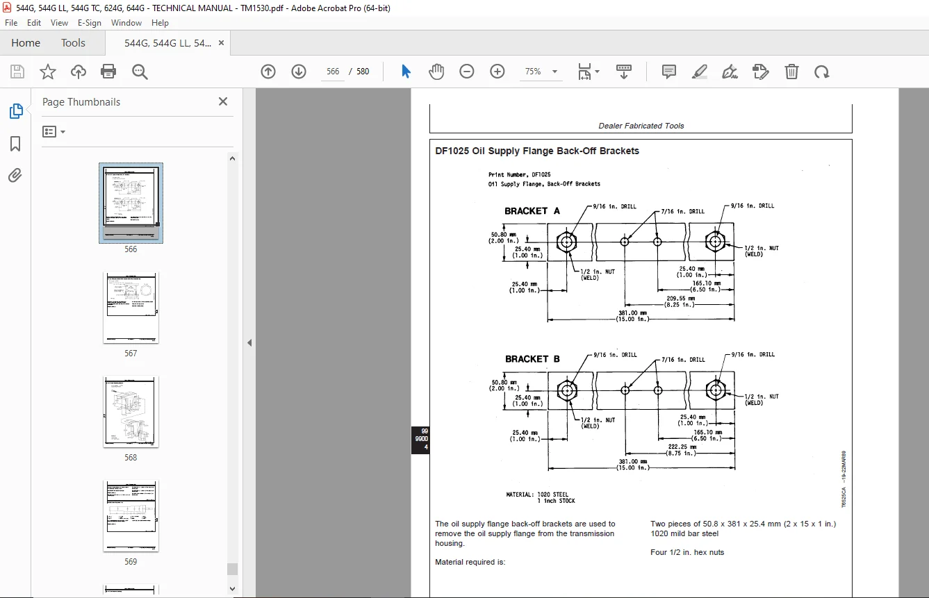
Dealer Fabricated Tools561
Dealer Fabricated Tools563
DF1055 And JD38002 Yoke Holding Tool563
DF1056 Input Pinion Shaft Adjusting Tool564
DF1057 Axle Adjusting Tool565
DF1025 Oil Supply Flange Back-Off Brackets566
DF1026 Pre-Load Clutch Pack Compression Ring Assembly Jig567
DF1027 Stand Mounting Bracket568
JDG588 Shaft Alignment Tool569
DF1044 Air Deflector Bushing570
DFT1118 Spanner Wrench571
DESCRIPTION:
John Deere 544G,544G LL,544G TC,624G,and 644G Loader Repair Technical Manual TM1530 – PDF DOWNLOAD
- Foreword:
- This manual is written for an experienced technician. Essential tools required in performing certain service work are identified in this manual and are recommended for use. Live with safety: Read the safety messages in the introduction of this manual and the cautions presented throughout the text of the manual.
- Operation and tests sections help you identify the majority of routine failures quickly. Information is organized in groups for the various components requiring service instruction. At the beginning of each group are summary listings of all applicable essential tools, service equipment and tools, other materials needed to do the job, service parts kits, specifications, wear tolerances, and torque values.
- Technical Manuals are concise guides for specific machines. They are on-the-job guides containing only the vital information needed for diagnosis, analysis, testing, and repair. Fundamental service information is available from other sources covering basic theory of operation, fundamentals of troubleshooting, general maintenance, and basic type of failures and their causes.
G.B 06/01/25