
John Deere 60D Excavator Operation & Test Technical Manual – PDF DOWNLOAD
$29.95
John Deere 60D Excavator Operation & Test Technical Manual – PDF DOWNLOAD
Description
John Deere 60D Excavator Operation & Test Technical Manual – PDF DOWNLOAD
FILE DETAILS:
John Deere 60D Excavator Operation & Test Technical Manual – PDF DOWNLOAD
Language : English
Pages :464
Downloadable : Yes
File Type : PDF
IMAGES PREVIEW OF THE MANUAL:
DESCRIPTION:
John Deere 60D Excavator Operation & Test Technical Manual – PDF DOWNLOAD
Foreword
- This manual is written for an experienced technician. Essential tools required in performing certain service work are identified in this manual and are recommended for use. Live with safety: Read the safety messages in the introduction of this manual and the cautions presented throughout the text of the manual. This is the safetyalert symbol. When you see this symbol on the machine or in this manual, be alert to the potential for personal injury. Technical manuals are divided in two parts:
- repair and operation and tests. Repair sections tell how to repair the components. Operation and tests sections help you identify the majority of routine failures quickly. Information is organized in groups for the various components requiring service instruction.
- At the beginning of each group are summary listings of all applicable essential tools, service equipment and tools, other materials needed to do the job, service parts kits, specifications, wear tolerances, and torque values. Technical Manuals are concise guides for specific machines.
- They are onthejob guides containing only the vital information needed for diagnosis, analysis, testing, and repair. Fundamental service information is available from other sources covering basic theory of operation, fundamentals of troubleshooting, general maintenance, and basic type of failures and their causes.
TABLE OF CONTENTS:
John Deere 60D Excavator Operation & Test Technical Manual – PDF DOWNLOAD
Contents 5
General Information 7
Safety 9
Recognize Safety Information 9
Follow Safety Instructions 9
Operate Only If Qualified 9
Wear Protective Equipment 10
Avoid Unauthorized Machine Modifications 10
Add Cab Guarding for Special Uses 10
Inspect Machine 10
Stay Clear of Moving Parts 11
Avoid High-Pressure Fluids 11
Beware of Exhaust Fumes 11
Prevent Fires 12
Prevent Battery Explosions 12
Handle Chemical Products Safely 12
Dispose of Waste Properly 13
Prepare for Emergencies 13
Use Steps and Handholds Correctly 13
Start Only From Operator’s Seat 13
Use and Maintain Seat Belt 14
Prevent Unintended Machine Movement 14
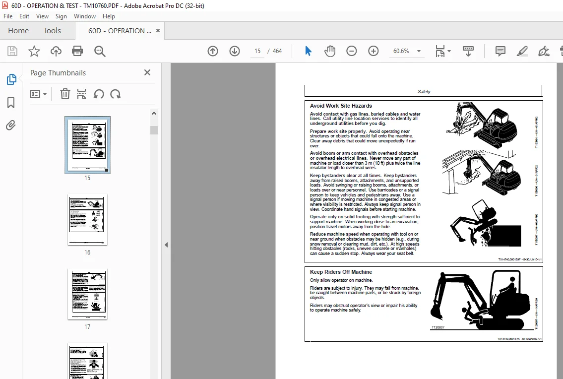
Avoid Work Site Hazards 15
Keep Riders Off Machine 15
Avoid Backover Accidents 16
Avoid Machine Tip Over 16
Use Special Care When Lifting Objects 17
Add and Operate Attachments Safely 17
Park and Prepare For Service Safely 17
Service Cooling System Safely 18
Remove Paint Before Welding or Heating 18
Make Welding Repairs Safely 18
Drive Metal Pins Safely 19
Diagnostics 22
Engine Control Unit (ECU) Diagnostic Trouble Codes 23
2900 — Spare Accelerator Sensor Upper Limit Error (P1226) 23
2901 — Spare Accelerator Sensor Lower Limit Error (P1225) 23
2902 — Spare Accelerator Sensor Intermittent Failure (P0224) 23
2903 — Spare Accelerator Sensor High Voltage Failure (P0223) 23
2904 — Spare Accelerator Sensor Low Voltage Failure (P0222) 23
2908 — Spare Accelerator Sensor Communication Error (P1227) 24
9100 — Accelerator Sensor Upper Limit Error (P1126) 24
9101 — Accelerator Sensor Lower Limit Error (P1125) 24
9102 — Accelerator Sensor Intermittent Failure (P0124) 24
9103 — Accelerator Sensor High Voltage Failure (P0123) 24
9104 — Accelerator Sensor Low Voltage Failure (P0122) 24
9700 — Oily Water Separator Mechanical Failure (P1151) 25
10001 — Oil Pressure Lower Limit Error (P1198) 25
10004 — Oil Pressure Switch Open Circuit Failure (P1192) 25
10700 — Air Cleaner Mechanical Failure (P1101) 25
10802 — Atmospheric Pressure Sensor Intermittent Failure (P2230 25
10803 — Atmospheric Pressure Sensor High Voltage Failure (P2229 25
10804 — Atmospheric Pressure Sensor Low Voltage Failure (P2228) 26
11000 — Engine Coolant Temperature Rise Error (P0217) 26
11002 — Engine Coolant Temperature Sensor Intermittent Failure 26
11003 — Engine Coolant Temperature Sensor High Voltage Failure 26
11004 — Engine Coolant Temperature Sensor Low Voltage Failure ( 26
16800 — Engine Control Unit (ECU) Supply Voltage Upper Limit Er 26
16801 — Engine Control Unit (ECU) Supply Voltage Lower Limit Er 27
19000 — Engine Overspeed (P0219) 27
63803 — Engine Fuel Rack Actuator High Output Failure (P1213) 27
63804 — Engine Fuel Rack Actuator Low Output Failure (P1212) 27
63807 — Engine Fuel Rack Actuator Mechanical Failure (P1211) 27
72902 — Air Heater Relay Intermittent Error (P1234) 27
72903 — Air Heater Relay Short Circuit Failure (P1233) 28
72904 — Air Heater Relay Open Circuit Failure (P1232) 28
107902 — Sensor 5V Intermittent Failure (P1644) 28
107903 — Sensor 5V High Voltage Failure (P0643) 28
107904 — Sensor 5V Low Voltage Failure (P0642) 28
113600 — Engine Control Unit (ECU) Internal Temperature Rise Er 28
113602 — Engine Control Unit (ECU) Internal Temperature Sensor 29
113603 — Engine Control Unit (ECU) Internal Temperature Sensor 29
113604 — Engine Control Unit (ECU) Internal Temperature Sensor 29
121003 — Engine Fuel Rack Position Sensor High Voltage Failure 29
121004 — Engine Fuel Rack Position Sensor Low Voltage Failure ( 29
148504 — Engine Control Unit (ECU) Main Relay Error (P0686) 30
204902 — Engine Fuel Rack Actuator Relay Intermittent Failure ( 30
204903 — Engine Fuel Rack Actuator Relay Short Circuit Failure 30
204904 — Engine Fuel Rack Actuator Relay Open Circuit Failure ( 30
205002 — Cold Start Device (CSD) Solenoid Valve Intermittent Fa 30
205003 — Cold Start Device (CSD) Solenoid Valve Short Circuit F 30
205004 — Cold Start Device (CSD) Solenoid Valve Open Circuit Fa 31
205903 — Exhaust Gas Recirculation (EGR) Step Motor A-Phase Sho 31
205904 — Exhaust Gas Recirculation (EGR) Step Motor A-Phase Ope 31
206003 — Exhaust Gas Recirculation (EGR) Step Motor B-Phase Sho 31
206004 — Exhaust Gas Recirculation (EGR) Step Motor B-Phase Ope 31
206103 — Exhaust Gas Recirculation (EGR) Step Motor C-Phase Sho 32
206104 — Exhaust Gas Recirculation (EGR) Step Motor C-Phase Ope 32
206203 — Exhaust Gas Recirculation (EGR) Step Motor D-Phase Sho 32
206204 — Exhaust Gas Recirculation (EGR) Step Motor D-Phase Ope 32
212200 — Engine Coolant Temperature Error (P1217) 32
212501 — Battery Charge Lower Limit Error (P1568) 33
212504 — Battery Charge Switch Open Circuit Failure (P1562) 33
220904 — Speed Sensor Low Voltage Failure (P0340) 33
221004 — Spare Speed Sensor Low Voltage Failure (P1340) 33
253012 — Engine Control Unit (ECU) Internal Flash ROM Error (P0 33
52272512 — CAN Communication Error (U0001) 33
52272612 — Engine Control Unit (ECU) Internal EEPROM Error (P06 34
52272712 — Engine Control Unit (ECU) Internal Sub CPU Cyclic Re 34
52272712 — Engine Control Unit (ECU) Internal Sub CPU ACKnowled 34
52272712 — Engine Control Unit (ECU) Internal Sub CPU Communica 34
52272812 — Engine Control Unit (ECU) Internal Map Format Error 34
Operational Checkout Procedure 35
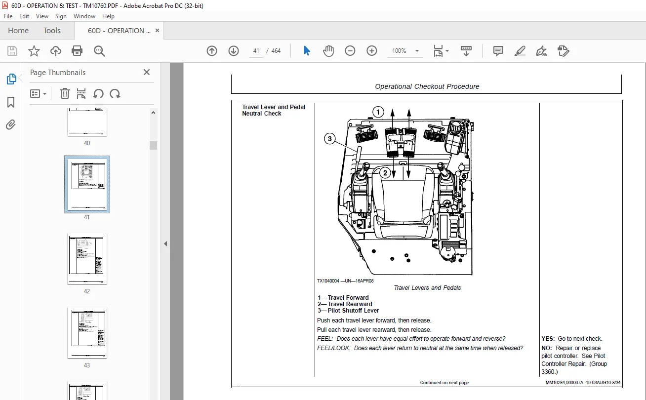
Operational Checkout Procedure 37
Operational Checkout 37
Operator Station Checks—Key Switch OFF, Engine OFF 37
Operator Station Checks—Key Switch ON, Engine OFF 38
Operational Checks—Key ON, Engine ON 44
Engine 67
Theory of Operation 69
Engine Component Location 69
Engine Fuel System Operation 72
Cooling System Operation 74
Engine Lubrication System Operation 75
Engine Intake and Exhaust System Operation 76
Exhaust Gas Recirculation (EGR) Operation 78
Engine Speed Control System Operation 80
Diagnostic Information 83
4TNV98 Yanmar 4-Cylinder Interim Tier IV Troubleshooting Manual 83
Diagnose Engine Malfunctions 83
Engine Cranks But Will Not Start 83
Engine Cranks But Will Not Start Diagnostic Procedure 83
Engine Misfires Or Runs Irregularly 84
Engine Misfires Or Runs Irregularly Diagnostic Procedure 84
Engine Does Not Develop Full Power 86
Engine Does Not Develop Full Power Diagnostic Procedure 86
Engine Overheats 88
Engine Overheats Diagnostics Procedure 88
Auto-Idle Does Not Work 89
Auto-Idle Does Not Work Diagnostics Procedure 89
Coolant Temperature Too Low 90
Coolant Temperature Too Low Diagnostics Procedure 90
Coolant in Oil or Oil in Coolant 91
Coolant in Oil or Oil in Coolant Diagnostics Procedure 91
Low Engine Oil Pressure 91
Low Engine Oil Pressure Diagnostics Procedure 91
High Engine Oil Pressure 92
High Engine Oil Pressure Diagnostics Procedure 92
Engine Uses Too Much Oil 93
Engine Uses Too Much Oil Diagnostics 93
Engine Uses Too Much Fuel 94
Engine Uses Too Much Fuel Diagnostic Procedure 94
Engine Emits Excessive White Exhaust Smoke 95
Engine Emits Excessive White Exhaust Smoke Diagnostic Procedure 95
Engine Emits Excessive Black or Gray Exhaust Smoke 96
Engine Emits Excessive Black or Gray Exhaust Smoke Diagnostic Pr 96
Fuel In Oil 98
Fuel In Oil Diagnostics Procedure 98
Tests 99
JT05801 Clamp-On Electronic Tachometer Installation 99
Fan Belt Check and Adjustment 99
Injection Pump Timing Check100
Fuel Injection Nozzle Test101
Engine Valve Lash (Clearance) Check and Adjust103
Engine Compression Pressure Test105
Engine Oil Pressure Test107
Electrical System110
System Information111
Electrical Diagram Information111
System Diagrams119
Explanation of Wire Markings119
Fuse and Relay Specifications119
System Functional Schematic, Component Location, and Wiring Diag122
System Functional Schematic125
Floor Harness (W1) Component Location136
Floor Harness (W1) Wiring Diagram139
Main Harness (W2) Component Location146
Main Harness (W2) Wiring Diagram151
Cab Harness (W4) Component Location153
Cab Harness (W4) Wiring Diagram155
Key Switch Harness (W5) Component Location157
Key Switch Harness (W5) Wiring Diagram157
Heater and Air Conditioner Harness (W6) Component Location158
Heater and Air Conditioner Harness (W6) Wiring Diagram159
Console Harness (W7) Component Location161
Console Harness (W7) Wiring Diagram162
Boom Light Harness (W8) Component Location163
Boom Light Harness (W8) Wiring Diagram164
Sub-System Diagnostics165
Starting and Charging Circuit Theory of Operation165
Monitor Controller Circuit Theory of Operation169
Engine Control Unit (ECU) Circuit Theory of Operation173
Travel Alarm Circuit Theory of Operation178
Pilot Shutoff Circuit Theory of Operation180
Windshield Wiper and Washer Circuit Theory of Operation182
Heater and Air Conditioner Circuit Theory of Operation185
Monitor Operation191
Monitor Menu Operation191
References193
Monitor Data Items193
Reading Engine Control Unit (ECU) Diagnostic Trouble Codes Using193
Engine Control Unit (ECU) Diagnostic Trouble Codes System Malfun194
Fuse Test196
Relay Test198
Pressure Sensor Test199
Solenoid Test199
Temperature Sensor Test200
Alternator Test201
Electrical Component Checks203
Component Checks203
Battery Remove and Install208
Engine Control Unit (ECU) Remove and Install209
Monitor Controller Remove and Install210
Key Switch Remove and Install211
Travel Alarm Remove and Install212
Right Console Remove and Install213
Disconnect Tab Retainer Connectors213
Disconnecting Spring Wire Clip Connectors214
Replace DEUTSCH DEUTSCH is a trademark of the Deutsch Co™ Conne214
Replace DEUTSCHDEUTSCH is a trademark of Deutsch Co™ Rectangula215
Install DEUTSCH DEUTSCH is a trademark of the Deutsch Co™ Conta216
Replace WEATHER PACK WEATHER PACK is a trademark of Packard Elec218
Install WEATHER PACK WEATHER PACK is a trademark of Packard Elec219
Replace (Pull Type) Metri-Pack™ Connectors220
Replace (Push Type) Metri-Pack™ Connectors221
Replace CINCHCINCH is a trademark of the Cinch Co™ Connectors221
Install CINCHCINCH is a trademark of the Cinch Co™ Contact223
Repair 32 and 48 Way CINCHCINCH is a trademark of the Cinch Co™224
Remove Connector Body from Blade Terminals226
Electrical Component Specifications227
Power Train229
Theory of Operation231
Track Adjuster and Recoil Spring Operation231
Travel Gearbox Operation232
Diagnostic Information233
Diagnose Undercarriage Components Malfunctions233
Noisy or Loose Track Chain233
Tight Track Chain233
Frequent Track Chain Sag Adjustment Required233
Excessive Oil Leakage From Front Idler, Track Rollers, or Carrie234
Bent Track Shoes (Steel Track)234
“Popping” Of Track235
Cracked Track Link235
Chipped Link Rails236
Individual Undercarriage Component Wear236
Measure Swing Bearing Wear237
Hydraulic System240
Theory of Operation241
Hydraulic System Operation241
Pilot System Operation241
Pilot Pump and Filter Operation242
Engine Speed Sensing Valve Operation243
Solenoid Valve Manifold Operation246
Pilot Control Valve Operation248
Control Lever Pattern Selector250
Travel Pilot Control Valve Operation252
Pilot Operation of Control Valve Operation255
Hydraulic Pump Operation258
Hydraulic Pump Regulator Operation259
Control Valve Operation265
Control Valve Check Valves Operation287
Main Relief Valve Operation291
Unload Valve Operation293
Control Valve Differential Pressure Reducing Valve Operation294
Circuit Relief and Anticavitation Valve Operation296
Flow Divider Valve Operation298
Swing Boom Make-Up Valve Operation299
Boom Reduced Leakage Valve Operation301
Blade Circuit Operation305
Swing Reduction Gearbox Operation308
Swing Motor Operation309
Swing Motor Crossover Relief Valve Operation310
Swing Motor Crossover Relief Valve Cushion Valve Operation312
Swing Motor Make-Up Check Valve Operation313
Swing Motor Park Brake Release Circuit Operation314
Center Joint Operation314
Travel Motor and Park Brake Valve Operation316
Travel Motor Speed Circuit Operation322
Hydraulic Cylinder Operation324
Return Filter Operation325
Diagnostic Information327
Diagnose Hydraulic System Malfunctions327
All Hydraulic Functions Slow327
Hydraulic Oil Overheats329
No Hydraulic Functions330
Poor Combined Operation331
Diagnose Pilot Circuit Malfunctions331
All Functions Cannot Be Operated331
Function Does Not Stop When Control Lever Released332
Some Functions Cannot Be Operated, All Others Are Normal333
All Functions Slow333
Some Functions Slow334
Function Moves in Opposite Direction335
Diagnose Dig Circuit Malfunctions336
All Dig Functions Slow or No Power336
Some Dig Functions Slow (Not All)336
Load Drifts Down When Control Valve Is In Neutral Position337
Load Falls When Control Valve Is Actuated To Raise Load With Eng338
Diagnose Swing Circuit Malfunctions339
Swing Speed Slow In Both Directions339
Swing Speed Slow or Does Not Operate In One Direction341
Upperstructure Drift With Swing Valve In Neutral342
Swing Function Does Not Operate342
Engine Stops During Combined Operation of Swing and Front Attach343
Diagnose Travel System Malfunctions343
Travel Park Brakes Do Not Apply343
Track Will Not Move In One Direction344
Track Will Not Move In Either Direction345
Machine Mistracks At All Speeds In Both Directions346
Slow Travel Speed Or Low Power347
Combined Travel And Dig Functions Slow Or No Power348
Travel Is “Jerky”349
Machine Will Not Hold Back And Park Brakes Engage And Disengage 350
Machine Will Not Turn Smoothly In One Direction Or Park Brake Gr350
Hydraulic Pump and Pilot Pump Line Identification351
Control Valve Line Identification355
Pilot Control Lever Pattern Selector Valve Line Connection358
Swing Motor Line Identification360
Travel System Component Location362
Travel Hydraulic System Line Connection365
Hydraulic System Schematic369
Hydraulic System Component Location385
Hydraulic System Pilot Line Connections389
Hydraulic System Main Line Connections393
Blade System Component Location397
Blade Hydraulic System Line Identification401
Tests405
JT05800 Digital Thermometer Installation405
JT02156A Digital Pressure/Temperature Analyzer Installation405
General Oil Cleanup Procedure Using Portable Filter Caddy406
Hydraulic Component Failure Cleanup Procedure Using Portable Fil408
Hydraulic Oil Warm-Up Procedure411
Pilot Pressure Regulating Valve Test and Adjustment412
Control Valve Spool Pilot Actuating Pressure Test414
Main Relief Valve Test and Adjustment415
Engine Speed Sensing Valve Test and Adjustment417
Unload Valve Test and Adjustment420
Control Valve Differential Reducing Valve Test and Adjustment423
Circuit Relief Valve Test and Adjustment425
Swing Motor Crossover Relief Valve Test and Adjustment428
Hydraulic Pump Regulator Test and Adjustment429
Pump Flow Test430
Swing Motor Leakage Test432
Travel Motor Leakage Test433
Cylinder Drift Test—Boom, Arm, Bucket, and Blade434
Heating and Air Conditioning437
Theory of Operation439
Air Conditioning System Cycle of Operation439
Diagnostic Information441
Diagnose Air Conditioning System Malfunctions441
Diagnose Heating System Malfunctions444
Heater and Air Conditioner Component Location446
Tests449
Refrigerant Cautions and Proper Handling449
Air Conditioner and Heater Operational Checks449
Visual Inspection Of Components449
Air Conditioner Compressor Clutch Test451
Refrigerant Leak Test451
Refrigerant Hoses and Tubing Inspection452
Air Conditioner Compressor Belt Check and Adjustment452
Operating Pressure Diagnostic Chart453
Page Number 5
Section 9000 7
Group 01 9
Section 9001 22
Group 10 23
Section 9005 35
Group 10 37
Section 9010 67
Group 05 69
Group 15 83
Group 25 99
Section 9015110
Group 05111
Group 10119
Group 15165
Group 16191
Group 20193
Section 9020229
Group 05231
Group 15233
Section 9025240
Group 05241
Group 15327
Group 25405
Section 9031437
Group 05439
Group 15441
Group 25449
S.M 4/1/25