John Deere 60D Excavator Repair TECHNICAL MANUAL TM10761- PDF DOWNLOAD
$27.95
John Deere 60D Excavator Repair TECHNICAL MANUAL TM10761- PDF DOWNLOAD
Description
John Deere 60D Excavator Repair TECHNICAL MANUAL TM10761- PDF DOWNLOAD
FILE DETAILS:
John Deere 60D Excavator Repair TECHNICAL MANUAL TM10761- PDF DOWNLOAD
Language : English
Pages :380
Downloadable : Yes
File Type : PDF
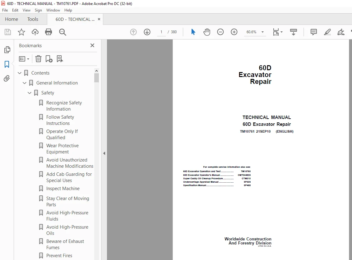
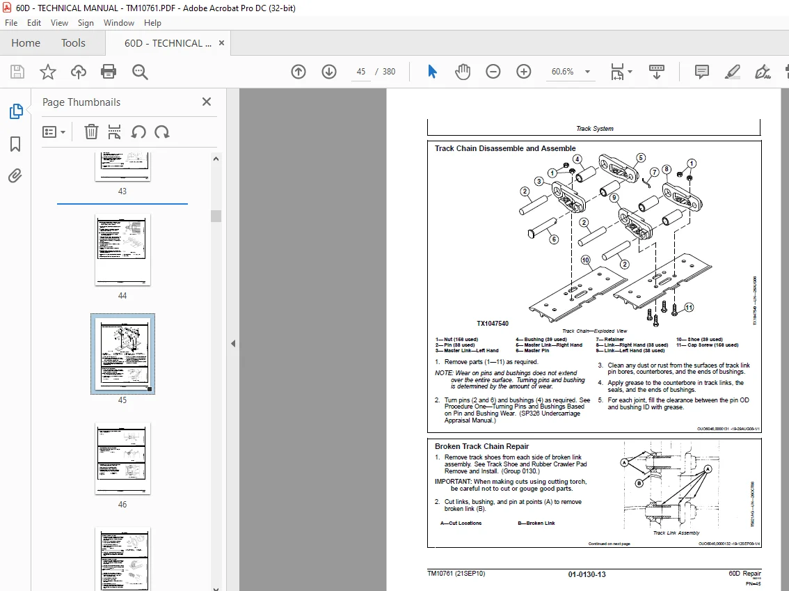
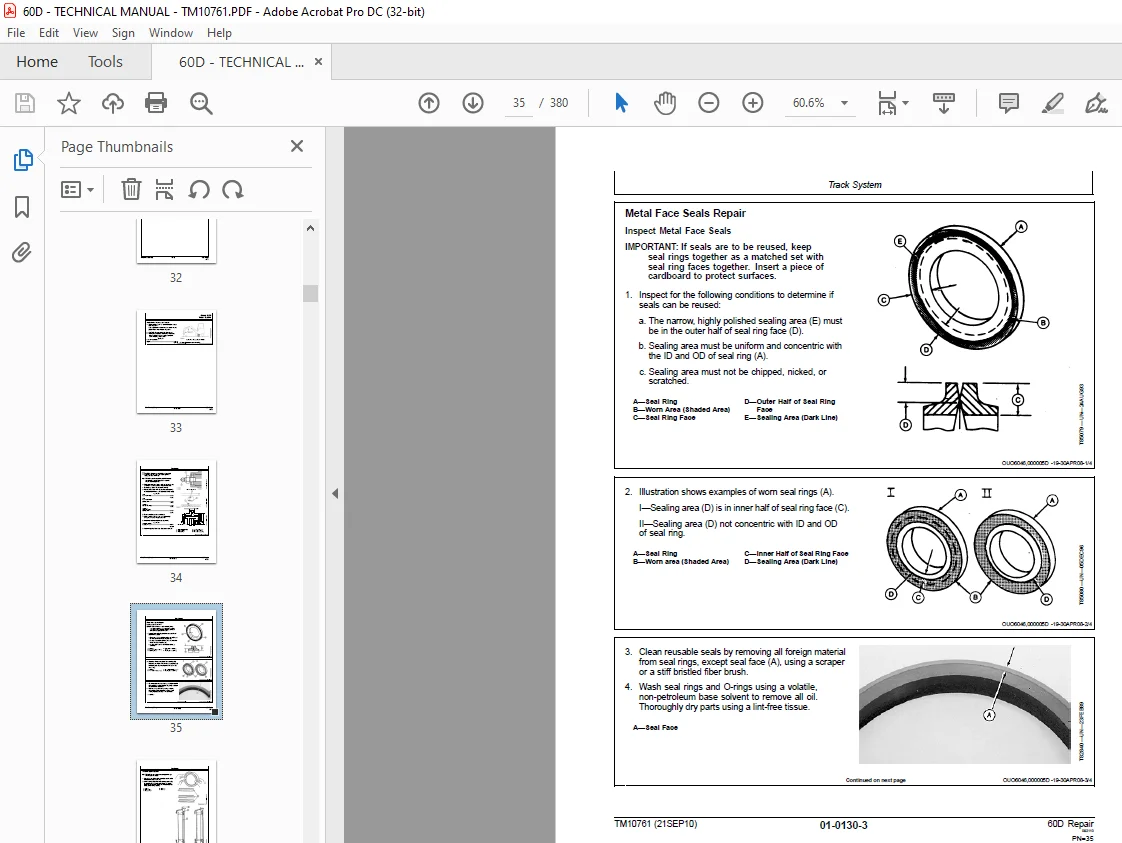
IMAGES PREVIEW OF THE MANUAL:
DESCRIPTION:
John Deere 60D Excavator Repair TECHNICAL MANUAL TM10761- PDF DOWNLOAD
Foreword
- This manual is written for an experienced technician. Essential tools required in performing certain service work are identified in this manual and are recommended for use. Live with safety: Read the safety messages in the introduction of this manual and the cautions presented throughout the text of the manual.
- This is the safetyalert symbol. When you see this symbol on the machine or in this manual, be alert to the potential for personal injury. Technical manuals are divided in two parts: repair and operation and tests. Repair sections tell how to repair the components. Operation and tests sections help you identify the majority of routine failures quickly. Information is organized in groups for the various components requiring service instruction.
- At the beginning of each group are summary listings of all applicable essential tools, service equipment and tools, other materials needed to do the job, service parts kits, specifications, wear tolerances, and torque values. Technical Manuals are concise guides for specific machines.
- They are onthejob guides containing only the vital information needed for diagnosis, analysis, testing, and repair. Fundamental service information is available from other sources covering basic theory of operation, fundamentals of troubleshooting, general maintenance, and basic type of failures and their causes.
TABLE OF CONTENTS:
John Deere 60D Excavator Repair TECHNICAL MANUAL TM10761- PDF DOWNLOAD
Contents 5
General Information 7
Safety 9
Recognize Safety Information 9
Follow Safety Instructions 9
Operate Only If Qualified 9
Wear Protective Equipment 10
Avoid Unauthorized Machine Modifications 10
Add Cab Guarding for Special Uses 10
Inspect Machine 10
Stay Clear of Moving Parts 11
Avoid High-Pressure Fluids 11
Avoid High-Pressure Oils 12
Beware of Exhaust Fumes 12
Prevent Fires 13
Prevent Battery Explosions 13
Handle Chemical Products Safely 13
Dispose of Waste Properly 14
Prepare for Emergencies 14
Use Steps and Handholds Correctly 14
Start Only From Operator’s Seat 14
Use and Maintain Seat Belt 15
Prevent Unintended Machine Movement 15
Avoid Work Site Hazards 16
Keep Riders Off Machine 16
Avoid Backover Accidents 17
Avoid Machine Tip Over 17
Use Special Care When Lifting Objects 18
Add and Operate Attachments Safely 18
Park and Prepare for Service Safely 18
Service Cooling System Safely 19
Remove Paint Before Welding or Heating 19
Make Welding Repairs Safely 19
Drive Metal Pins Safely 20
Torque Values 21
Unified Inch Bolt and Cap Screw Torque Values 21
Metric Bolt and Cap Screw Torque Values 22
Additional Metric Cap Screw Torque Values 23
Check Oil Lines and Fittings 24
Service Recommendations for O-Ring Boss Fittings 24
Service Recommendations For Flat Face O-Ring Seal Fittings 26
Service Recommendations for 37° Flare and 30° Cone Seat Connecto 27
Service Recommendations For Flared Connections—Straight or Taper 28
Service Recommendations For Inch Series Four Bolt Flange Fitting 29
Service Recommendations for Metric Series Four Bolt Flange Fitti 30
Tracks 31
Track System 33
Track Roller Remove and Install 33
Metal Face Seals Repair 35
Track Carrier Roller Remove and Install 37
Measure Rubber Track Lugs 38
Remove and Install Rubber Track 39
Metal Track Components Inspection 41
Track Shoe and Rubber Crawler Pad Remove and Install 43
Track Chain Remove and Install 43
Track Chain Disassemble and Assemble 45
Broken Track Chain Repair 45
Sprocket Remove and Install 47
Front Idler Remove and Install 47
Front Idler Disassemble and Assemble 48
Track Adjuster and Recoil Spring Remove and Install 50
Track Adjuster and Recoil Spring Disassemble and Assemble 51
Track Adjuster Cylinder Disassemble and Assemble 56
Axles, Differentials and Suspension Systems 59
Axle Shaft, Bearings, and Reduction Gears 61
Travel Gearbox Remove and Install 61
Travel Gearbox Disassemble and Assemble 63
Hydraulic System 69
Travel Motor and Park Brake Remove and Install 69
Travel Motor Disassemble and Assemble 70
Travel Motor Cover Disassemble and Assemble 76
Travel Motor and Park-Brake Start-Up Procedure 77
Engine 79
Removal and Installation 81
Engine Remove and Install 81
Exhaust Manifold Remove and Install 86
Valve Cover Remove and Install 87
Rocker Arm Assembly Remove and Install 88
Rocker Arm Assembly Disassemble and Assemble 88
Rocker Arm Assembly Inspection 90
Intake Manifold Remove and Install 93
Water Pump Remove and Install 94
Cylinder Head Remove and Install 95
Cylinder Head Disassemble and Assemble 98
Cylinder Head Inspection101
Crankshaft Front Seal Replace105
Timing Gear Cover Remove and Install106
Timing Gear Case Remove and Install108
Cylinder Block Disassemble and Assemble113
Cylinder Block Inspection114
Rear Oil Seal Remove and Install118
Camshaft Remove and Install119
Flywheel Remove and Install124
Flywheel Disassemble and Assemble124
Flywheel Housing Remove and Install125
Oil Pan Remove and Install126
Crankshaft Remove and Install127
Crankshaft Disassemble and Assemble130
Crankshaft Inspection131
Piston and Connecting Rod Remove and Install135
Piston and Connecting Rod Disassemble and Assemble139
Piston and Connecting Rod Inspection143
Oil Pump Remove and Install148
Oil Pump Inspection149
Thermostat Remove and Install151
Thermostat Inspection151
Fuel Injection Pump Remove and Install152
Fuel Injection Nozzles Remove and Install158
Fuel Injection Nozzles Disassemble and Assemble160
Muffler Remove and Install163
Starter Remove and Install164
Alternator Remove and Install165
Alternator Disassemble and Assemble166
Engine Auxiliary Systems169
Cooling System171
Radiator Remove and Install171
Hydraulic Oil Cooler Remove and Install174
Fan, Fan Guard, and Fan Shroud Remove and Install175
Alternator Belt Remove and Install177
Air Conditioning Belt Remove and Install177
Coolant Surge Tank Remove and Install178
Intake System179
Air Cleaner Remove and Install179
External Fuel Supply Systems181
Fuel Tank Remove and Install181
Primary Fuel Filter (Water Separator) Remove and Install182
Final Fuel Filter Remove and Install182
Dampener Drive (Flex Coupling)183
Elements185
Dampener Drive (Flex Coupling) Remove and Install185
Frame or Supporting Structure187
Frame Installation189
Welding On Machine189
Welding Repair of Major Structure189
Chassis Weights191
Counterweight Remove and Install191
Operators Station193
Removal and Installation195
Cab Remove and Install195
Operator Enclosure199
Windowpanes Dimensions199
Seat and Seat Belt203
Seat Remove and Install203
Seat Belt Remove and Install203
Left and Right Console Covers Remove and Install204
Heating and Air Conditioning System207
Refrigerant Cautions and Proper Handling207
Flush and Purge Air Conditioner System208
R134a Refrigerant Oil Information210
R134a Refrigerant Recovery / Recycling and Charging Station Inst211
Recover R134a Refrigerant211
Evacuate R134a System212
Charge R134a System213
Compressor Remove and Install214
Condenser Remove and Install215
Heater and Air Conditioner Remove and Install216
Receiver-Dryer Remove and Install217
Bulldozers (Blade)219
Blades221
Blade Remove and Install221
Blade Disassemble and Assemble223
Hydraulic System225
Blade Pilot Controller Remove and Install225
Blade Pilot Controller Disassemble and Assemble226
Blade Cylinder Remove and Install228
Blade Cylinder Disassemble and Assemble229
Excavator231
Buckets233
Bucket Remove and Install233
Bucket Pin-Up Data234
Frames237
Bucket Link Remove and Install237
Arm Remove and Install240
Boom Remove and Install244
Swing Boom Post Remove and Install247
Inspect Pins and Bushings—Front Attachment250
Bushing and Seal Remove and Install254
Hydraulic System255
Apply Vacuum to Hydraulic Oil Tank255
Hydraulic Oil Cleanup Procedure Using Portable Filter Caddy255
Hydraulic Pump Start-Up Procedure255
Hydraulic Pump Remove and Install256
Hydraulic Pump Disassemble257
Hydraulic Pump Assemble259
Hydraulic Pump Regulator Disassemble and Assemble262
Pilot Pump Remove and Install264
Pilot Pressure Regulating Valve Remove and Install265
Pilot Shutoff Solenoid Remove and Install265
Solenoid Valve Manifold Remove and Install266
Solenoid Valve Manifold Disassemble and Assemble267
Pilot Valve (Left and Right) Remove and Install269
Pilot Valve (Left and Right) Disassemble and Assemble272
Travel Pilot Valve Remove and Install274
Travel Pilot Valve Disassemble and Assemble275
Auxiliary Pilot Control Valve Remove and Install276
Auxiliary Pilot Control Valve Disassemble and Assemble277
Boom Swing Pilot Control Valve Remove and Install279
Boom Swing Pilot Control Valve Disassemble and Assemble280
Control Valve Remove and Install282
Control Valve Disassemble and Assemble283
Hydraulic Oil Tank Remove and Install314
Hydraulic Oil Tank Dissemble and Assemble316
Restriction Valve Remove and Install318
Hydraulic Oil Cooler Bypass Valve Remove and Install319
Boom Cylinder Remove and Install320
Boom Cylinder Disassemble and Assemble323
Arm Cylinder Remove and Install326
Arm Cylinder Disassemble and Assemble328
Bucket Cylinder Remove and Install331
Bucket Cylinder Disassemble and Assemble334
Boom Swing Cylinder Remove and Install337
Boom Swing Cylinder Disassemble and Assemble340
Hydraulic Cylinder Bleed Procedure343
Swing or Pivoting System345
Mechanical Drive Elements347
Swing Gearbox Remove and Install347
Swing Gearbox Disassemble and Assemble348
Swing Bearing Remove and Install352
Hydraulic System355
Center Joint Remove and Install355
Center Joint Disassemble and Assemble357
Center Joint Air Test358
Swing Motor and Park Brake Remove and Install358
Swing Motor and Park Brake Disassemble and Assemble359
Swing Motor and Park Brake Inspection361
Swing Motor Start-Up Procedure362
Crossover Relief Valve Disassemble and Assemble363
Make-Up Valve Disassemble and Assemble363
Dealer Fabricated Tools365
Dealer Fabricated Tools367
ST4920 Track Recoil Spring Disassembly and Assembly Tool367
DFT1087 Track Recoil Spring Disassembly and Assembly Guard Tool371
DFT1112A Spacer372
Page Number 5
Section 000 7
Group 0001 9
Group 0003 21
Section 01 31
Group 0130 33
Section 02 59
Group 0250 61
Group 0260 69
Section 04 79
Group 0400 81
Section 05169
Group 0510171
Group 0520179
Group 0560181
Section 07183
Group 0752185
Section 17187
Group 1740189
Group 1749191
Section 18193
Group 1800195
Group 1810199
Group 1821203
Group 1830207
Section 32219
Group 3201221
Group 3260225
Section 33231
Group 3302233
Group 3340237
Group 3360255
Section 43345
Group 4350347
Group 4360355
Section 99365
Group 9900367
S.M 4/1/25