John Deere 644J Loader Repair Parts Manual S.N.611232 PDF DOWNLOAD
$29.95
John Deere 644J Loader Repair Parts Manual S.N.611232 PDF DOWNLOAD
Description
John Deere 644J Loader Repair Parts Manual S.N.611232 PDF DOWNLOAD
FILE DETAILS:
John Deere 644J Loader Repair Parts Manual S.N.611232 PDF DOWNLOAD
Language : English
Pages : 474
Downloadable : Yes
File Type : PDF
IMAGES PREVIEW OF THE MANUAL:
TABLE OF CONTENTS:
John Deere 644J Loader Repair Parts Manual S.N.611232 PDF DOWNLOAD
Contents 5
General Information 9
Safety Information 11
Recognize Safety Information 11
Follow Safety Instructions 11
Operate Only If Qualified 12
Wear Protective Equipment 12
Avoid Unauthorized Machine Modifications 12
Add Cab Guarding For Special Uses 13
Inspect Machine 13
Stay Clear of Moving Parts 13
Avoid High-Pressure Fluids 14
Avoid High-Pressure Oils 14
Beware of Exhaust Fumes 15
Prevent Fires 15
Prevent Battery Explosions 15
Handle Chemical Products Safely 16
Dispose of Waste Properly 16
Prepare for Emergencies 16
Use Steps and Handholds Correctly 17
Start Only From Operator’s Seat 17
Use and Maintain Seat Belt 17
Prevent Unintended Machine Movement 18
Avoid Work Site Hazards 19
Use Special Care When Operating Loader 20
Keep Riders Off Machine 20
Avoid Backover Accidents 21
Avoid Machine Tip Over 21
Operating on Slopes 22
Operating or Traveling On Public Roads 22
Inspect and Maintain ROPS 23
Add and Operate Attachments Safely 23
Park And Prepare For Service Safely 24
Service Cooling System Safely 24
Remove Paint Before Welding or Heating 25
Make Welding Repairs Safely 26
Drive Metal Pins Safely 26
Wheels 27
Powered Wheels And Fasteners 29
Wheel Remove and Install 29
Tire Remove and Install 30
Axles And Suspension Systems 33
Removal And Installation 35
TeamMate™ IV Axles 35
Front Axle and Differential Remove and Install 35
Rear Axle and Differential Remove and Install 40
Axle Oscillating Supports Disassemble and Assemble 48
Input Drive Shafts and U-Joints 52
Universal Joint and Drive Shaft Remove and Install 52
Universal Joint and Drive Shaft Disassemble and Assemble 54
Axle Shaft, Bearings, and Reduction Gears 57
TeamMate™ IV Axles 57
Hydraulic System 59
Differential Lock Solenoid Valve Remove and Install 59
Axle Circulation System 62
Axle Oil Coolers Disassemble and Assemble 64
Transmission 65
Removal And Installation 67
Transmission Remove and Install 67
Gears, Shafts, Bearings And Power Shift Clutch 71
Torque Converter Remove and Install (Engine Removed) 71
Torque Converter and Housing Remove and Install 79
Clutches and Input and Output Shafts Remove and Install 88
Input Shaft Disassemble and Assemble114
Hydraulic System119
Transmission Pump Remove and Install119
Converter Minimum Pressure Regulator Valve Remove and Install125
Transmission Control Valve Remove and Install127
Transmission Control Valve Disassemble and Assemble131
Converter Relief Valve Repair146
Transmission Internal Oil Pipes and Tubes148
Remove and install148
Engine153
Removal and Installation155
PowerTech Plus™ 45 L (4045) and 68 L (6068) John Deere Engines155
Engine Remove and Install155
Engine Crankshaft Dampener Remove and Install164
Engine Auxiliary Systems167
Cold Weather Starting Aids169
Engine Coolant Heater Remove and Install169
Cooling System171
Serpentine Belt Remove and Install171
Fan and Fan Drive Motor Remove and Install173
Fan Drive and Axle Circulation Pump Remove and Install177
Intercooler Remove and Install178
Radiator Remove and Install180
Hydraulic Oil Cooler Remove and Install185
Transmission Oil Cooler Remove and Install186
Cooling Package Plenum Remove and Install188
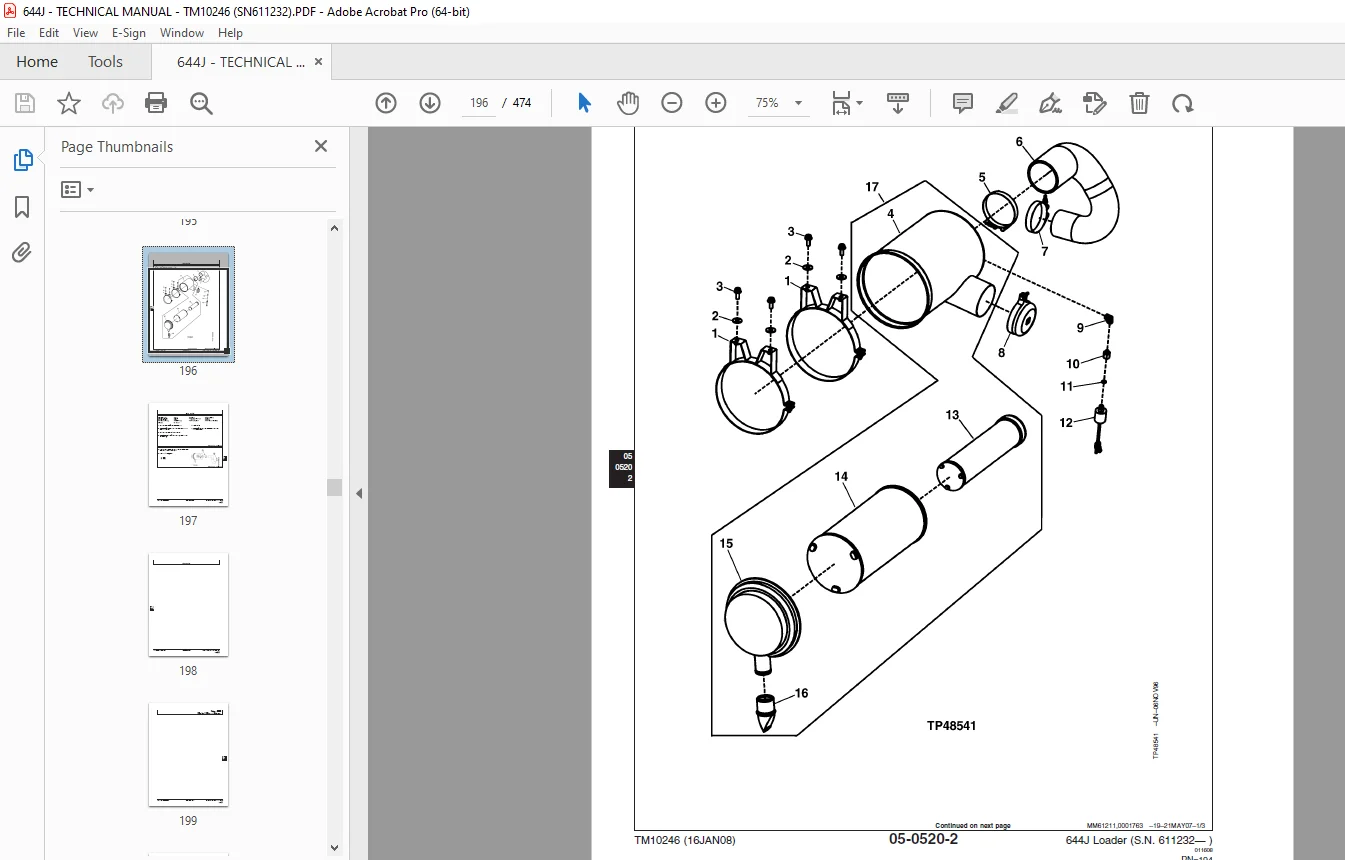
Intake System196
Air Cleaner Remove and Install196
External Exhaust System200
Muffler Remove and Install200
External Fuel Supply Systems203
Fuel Tank Remove and Install203
Dampener Drive207
Elements209
Output Dampener Remove and Install209
Steering System211
Hydraulic System213
Steering Valve Remove and Install213
Steering Column Remove and Install218
Steering Column Disassemble and Assemble219
Steering Cylinder Remove and Install (SN —618143)220
Steering Cylinder Remove and Install (SN 618144— )221
Steering Cylinder Bushings Remove and Install (SN —618143)222
Steering Cylinder Bushings Remove and Install (SN 618144— )223
Service Brakes225
Active Elements228
Brake Pedal and Linkage Disassemble and Assemble228
Brake Assembly Remove And Install230
Hydraulic System231
Brake Valve Remove and Install231
Brake Accumulator Remove and Install233
Park Brake235
Active Elements237
Park Brake Remove and Install237
Park Brake Disassemble and Assemble240
Hydraulic System245
Park Brake Release Solenoid Valve Remove and Install245
Park Brake Pressure Switch Remove and Install247
Frame Or Supporting Structure249
Frame Installation251
Engine and Loader Frame Separate251
Upper Pivot Bearing and Seals Remove and Install254
Lower Pivot Bearing and Seals Remove and Install256
Frame Bottom Guards259
Fuel Tank Guard Remove and Install259
Front Axle Guard Remove and Install259
Transmission Bottom Guard Remove and Install260
Chassis Weights261
Counterweights Remove and Install261
Rear Counterweight Remove and Install263
Operator’s Station265
Removal And Installation267
Cab Remove267
Cab Install273
Operator Enclosure275
Front Windshield Wiper Adjust275
Heating And Air Conditioning277
R134a Refrigerant Cautions277
R134a Compressor Oil Charge Check277
R134a Compressor Oil Removal278
R134a Component Oil Charge279
Leak Testing280
Refrigerant Hoses and Tubing Inspection280
R134a Refrigerant Recovery, Recycling and Charging Station Installation Procedure281
R134a System Recover282
R134a System Evacuate283
R134a System Charge285
Air Conditioner System Cleaning Procedures286
Air Conditioner System Purge287
Air Conditioner System Flush288
Air Conditioning Module With Heater/Evaporator Coil290
Heater/Evaporator Core Remove and Install292
Expansion Valve Remove and Install294
Freeze Control Switch Remove and Install294
Freeze Control Switch Bench Test296
Heater Control Valve Remove and Install297
Heater Control Valve Leak Check298
Main Blower Assembly Remove And Install299
Pressurizer Motor Assembly Remove and Install300
Receiver-Dryer and Condenser Remove and Install301
A/C Binary Pressure Switch Remove and Install302
Fresh Air Filter Remove and Install303
Recirculating Air Filter Remove and Install306
Compressor Remove and Install308
Compressor Clutch—R134a Disassemble and Assemble311
Clutch Hub Clearance—R134a Check312
Compressor Manifold—R134a Inspect313
Compressor—R134a Disassemble, Inspect, and Assemble314
Sheet Metal And Styling319
Hood or Engine Enclosure321
Hood Remove and Install321
Engine Side Shields Remove and Install322
Grille and Fan Housing325
Grille and Fan Housing Remove and Install325
Loader329
Bucket331
Bucket Remove and Install331
Welded-On Bucket Cutting Edges Remove and Install337
Bolt-On Cutting Edges and Wear Plates Remove and Install338
Cracked Cutting Edge Repair340
Frames341
NeverGrease™ Pin Joints341
Loader Bucket Tilt Linkage Remove and Install344
Bucket Linkage Seals and Bushings Remove and Install347
Loader Boom Bushings and Seals Remove and Install349
Boom Remove and Install352
Powerllel™ Leveling Link Disassemble and Assemble356
Powerllel™ Bellcrank Remove and Install360
Powerllel™ Bucket Cylinder Remove and Install364
Powerllel™ Bucket Link Disassemble and Assemble370
Powerllel™ Guide Links Remove and Install376
Powerllel™ Coupler Disassemble and Assemble380
Powerllel™ Loader Boom Disassemble and Assemble384
Hi-Vis Coupler Disassemble and Assemble390
Hydraulic System395
Hydraulic Oil Cleanup Procedure Using Portable Filter Caddy395
Hydraulic Pump Remove and Install395
Hydraulic Pump Disassemble and Assemble398
Hydraulic Pump Control Valve Remove and Install420
Hydraulic Pump Control Valve Disassemble and Assemble422
Loader Control Valve Remove and Install424
Loader Control Valve Disassemble and Assemble427
Auxiliary Valve Section and Bucket Section Disassemble and Assemble428
Boom Valve Section Disassemble and Assemble429
Relief Valve Disassemble and Assemble430
Bucket Circuit Relief Valve Disassemble and Assemble430
Load Sense Relief Valve Disassemble and Assemble431
Anti-Cavitation Relief Valve Disassemble and Assemble431
Boom Cylinder Remove and Install—185 Series432
Bucket Cylinder Remove and Install—185 Series435
Boom Cylinder Piston Wear Ring Configuration437
Boom and Bucket Cylinder Bushings and Seals Remove and Install438
Hydraulic Reservoir Remove and Install439
Pilot Control Valve Remove and Install441
Pilot Control Valve Disassemble and Assemble443
Boom Down Accumulator Remove and Install447
Pressure Reducing Valve Manifold Remove and Install449
Pressure Reducing Valve Manifold Disassemble and Assemble451
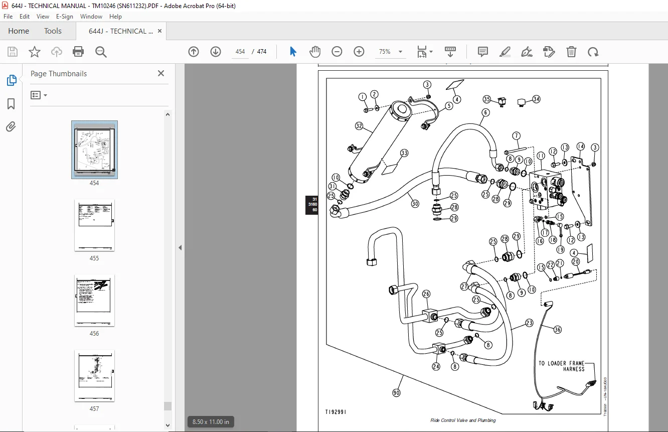
Ride Control Valve Remove and Install453
Ride Control Valve Disassemble and Assemble456
Pin Disconnect Valve Remove and Install459
Pin Disconnect Valve Disassemble and Assemble460
Dealer Fabricated Tools461
Dealer Fabricated Tools463
DFT1132 Hydraulic Pump Removal And Installation Tool463
DFT1149 Pre-Load Clutch Pack Compression Ring Tool464
DFT1158 Torque Converter Adapter Plate465
DFT1063 Lifting Bracket466
DFRW20 Compressor Holding Fixture467
DESCRIPTION:
John Deere 644J Loader Repair Parts Manual S.N.611232 PDF DOWNLOAD
Foreword :
- This manual is written for an experienced technician. Essential tools required in performing certain service work are identified in this manual and are recommended for use. Live with safety: Read the safety messages in the introduction of this manual and the cautions presented throughout the text of the manual.
- This is the safety-alert symbol. When you see this symbol on the machine or in this manual, be alert to the potential for personal injury. Technical manuals are divided in two parts: repair and operation and tests. Repair sections tell how to repair the components.
- Operation and tests sections help you identify the majority of routine failures quickly. Information is organized in groups for the various components requiring service instruction. At the beginning of each group are summary listings of all applicable essential tools, service equipment and tools, other materials needed to do the job, service parts kits, specifications, wear tolerances, and torque values.
- Technical Manuals are concise guides for specific machines. They are on-the-job guides containing only the vital information needed for diagnosis, analysis, testing, and repair. Fundamental service information is available from other sources covering basic theory of operation, fundamentals of troubleshooting, general maintenance, and basic type of failures and their causes.
G.B 06/01/25