Trusted Business
Verified & Licensed
Virus Free Files
100% Safe Downloads
Secure Payment
SSL Protected
Instant Delivery
Available Immediately
Technical Manual (Operation & Test) for John Deere 644K Loader PDF
$36.95
John Deere 644K 4WD Loader Operation & Test Technical Manual TM13116X19 – PDF DOWNLOAD
Instant PDF Download
Available immediately
Save to Your Device
Download & keep forever
Antivirus Scanned
100% virus-free
Trusted Worldwide
175,000+ customers
Description
John Deere 644K 4WD Loader Operation & Test Technical Manual TM13116X19 – PDF DOWNLOAD
FILE DETAILS:
John Deere 644K 4WD Loader Operation & Test Technical Manual TM13116X19 – PDF DOWNLOAD
Language : English
Pages : 1390
Downloadable : Yes
File Type : PDF
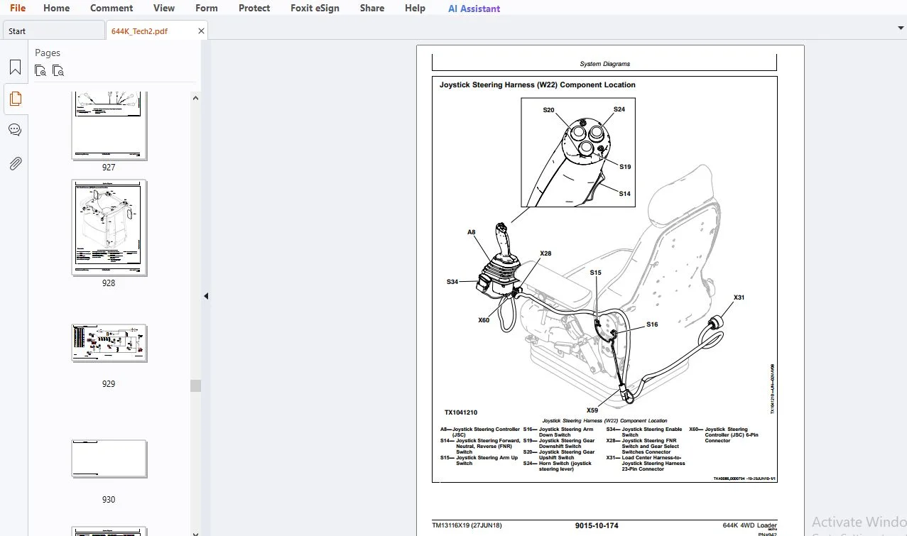
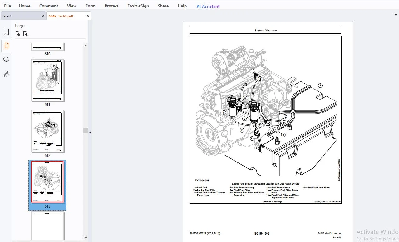
IMAGES PREVIEW OF THE MANUAL:
DESCRIPTION:
John Deere 644K 4WD Loader Operation & Test Technical Manual TM13116X19 – PDF DOWNLOAD
- READ THIS MANUAL carefully to learn how to operate and service your machine correctly. Failure to do so could result in personal injury or equipment damage.
- This manual and safety signs on your machine may also be available in other languages. (See your John Deere dealer to order.)
- THIS MANUAL SHOULD BE CONSIDERED a permanent part of your machine and should remain with the machine when you sell it.
- MEASUREMENTS in this manual are given in both metric and customary U.S. unit equivalents. Use only correct replacement parts and fasteners. Metric and inch fasteners may require a specific metric or inch wrench.
- RIGHT-HAND AND LEFT-HAND sides are determined by facing in the direction of forward travel.
- WRITE PRODUCT IDENTIFICATION NUMBERS (P.I.N.) in the Machine Numbers section. Accurately record all the numbers to help in tracing the machine should it be stolen. Your dealer also needs these numbers when you order parts. File the identification numbers in a secure place off the machine.
- WARRANTY is provided as part of John Deere’s support program for customers who operate and maintain their equipment as described in this manual. The warranty is explained on the warranty certificate or statement which you should have received from your dealer.
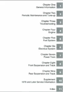
TABLE OF CONTENTS:
John Deere 644K 4WD Loader Operation & Test Technical Manual TM13116X19 – PDF DOWNLOAD
Contents........................................................................................................................   5
	General Information.........................................................................................................   7
		Safety..................................................................................................................   9
			Information for European Union Directives and Eurasian Economic Union Technical Regulations Compliance..............   9
			Recognize Safety Information........................................................................................  10
			Follow Safety Instructions..........................................................................................  11
			Operate Only If Qualified...........................................................................................  11
			Wear Protective Equipment...........................................................................................  11
			Avoid Unauthorized Machine Modifications............................................................................  12
			Inspect Machine.....................................................................................................  12
			Stay Clear of Moving Parts..........................................................................................  12
			Avoid High-Pressure Fluids..........................................................................................  13
			Avoid High-Pressure Oils............................................................................................  13
			Work In Ventilated Area.............................................................................................  13
			Prevent Fires.......................................................................................................  14
			Avoid Static Electricity Risk When Refueling........................................................................  14
			High Debris Applications............................................................................................  15
			Clean Debris from Machine...........................................................................................  15
			Prevent Battery Explosions..........................................................................................  15
			Handle Chemical Products Safely.....................................................................................  16
			Handle Starting Fluid Safely........................................................................................  16
			Decommissioning — Proper Recycling and Disposal of Fluids and Components............................................  17
			Prepare for Emergencies.............................................................................................  17
			In Case of Machine Fire.............................................................................................  18
			Add Cab Guarding for Special Uses...................................................................................  18
			Do Not Use Starting Fluid...........................................................................................  18
			Use Steps and Handholds Correctly...................................................................................  18
			Start Only From Operator's Seat.....................................................................................  19
			Use and Maintain Seat Belt..........................................................................................  19
			Prevent Unintended Machine Movement.................................................................................  19
			Avoid Work Site Hazards.............................................................................................  20
			Avoid Power Lines...................................................................................................  20
			Use Special Care When Operating Loader..............................................................................  21
			Keep Riders Off Machine.............................................................................................  21
			Avoid Backover Accidents............................................................................................  21
			Avoid Machine Tip Over..............................................................................................  22
			Operating on Slopes.................................................................................................  22
			Operating or Traveling On Public Roads..............................................................................  23
			Inspect and Maintain ROPS...........................................................................................  23
			Travel Safely.......................................................................................................  23
			Prevent Acid Burns..................................................................................................  24
			Add and Operate Attachments Safely..................................................................................  24
			Park and Prepare for Service Safely.................................................................................  25
			Service Machines Safely.............................................................................................  25
			Service Cooling System Safely.......................................................................................  25
			Service Tires Safely................................................................................................  26
			Remove Paint Before Welding or Heating..............................................................................  26
			Make Welding Repairs Safely.........................................................................................  27
			Drive Metal Pins Safely.............................................................................................  27
			Use Proper Lifting Equipment........................................................................................  27
	Diagnostics.................................................................................................................  46
		Engine Control Unit (ECU) Diagnostic Trouble Codes......................................................................  47
			Engine Control Unit (ECU) Diagnostic Trouble Codes..................................................................  47
			000091.03 — Accelerator Pedal Short to Power........................................................................  48
			000091.04 — Accelerator Pedal Open or Short.........................................................................  49
			000091.14 — Accelerator Pedal Sensor Invalid........................................................................  49
			000170.00 — Engine Air Filter Restricted............................................................................  49
				Engine Air Filter Restricted Diagnostic Procedure...............................................................  50
			000676.03 — Engine Heat Short to Power..............................................................................  51
			000676.05 — Engine Heat Open or Short...............................................................................  52
			001321.05 — Starter Relay Open Circuit..............................................................................  53
			001321.06 — Starter Relay High Current..............................................................................  54
			001321.09 — Starter Signal Invalid..................................................................................  55
			002003.09 — CAN Communication Lost for TCU..........................................................................  55
				CAN Communication Lost For TCU Diagnostic Procedure.............................................................  55
			002033.09 — CAN Communication Lost for VCU..........................................................................  57
				CAN Communication Lost for VCU Diagnostic Procedure.............................................................  57
		Transmission Control Unit (TCU) Diagnostic Trouble Codes................................................................  61
			Transmission Control Unit (TCU) Diagnostic Trouble Codes............................................................  61
			000091.09 — Timeout EEC2 Message....................................................................................  61
				Timeout EEC2 Message Diagnostic Procedure.......................................................................  61
			000161.00 — Engine Speed Extremely High.............................................................................  62
			000513.02 — Percent Torque Invalid..................................................................................  62
				Percent Torque Invalid Diagnostic Procedure.....................................................................  62
			000513.09 — Timeout EEC1 Message....................................................................................  63
				Timeout EEC1 Message Diagnostic Procedure.......................................................................  63
			000514.02 — Friction Invalid........................................................................................  64
				Friction Invalid Diagnostic Procedure...........................................................................  64
			000514.09 — Timeout EEC3 Message....................................................................................  65
				Time out EEC3 Message Diagnostic Procedure......................................................................  65
			000544.02 — Reference Torque Invalid................................................................................  66
				Reference Torque Invalid Diagnostic Procedure...................................................................  66
			000544.09 — Timeout Engine Configuration Message....................................................................  67
				Timeout Engine Configuration Message Diagnostic Procedure.......................................................  67
			000777.02 — Torque Converter Clutch Slippage........................................................................  68
				Torque Converter Clutch Slippage Diagnostic Procedure...........................................................  68
			000777.03 — Torque Converter Lockup Solenoid Short to Power.........................................................  70
				Torque Converter Lockup Solenoid Short to Power Diagnostic Procedure............................................  70
			000777.04 — Torque Converter Lockup Solenoid Short to Ground........................................................  71
				Torque Converter Lockup Solenoid Short to Ground Diagnostic Procedure...........................................  71
			000777.05 — Torque Converter Lockup Solenoid Open Circuit...........................................................  72
				Torque Converter Lockup Solenoid Open Circuit Diagnostic Procedure..............................................  72
			000928.03 — Axle Disconnect Solenoid Short to Power.................................................................  73
				Axle Disconnect Solenoid Short to Power Diagnostic Procedure....................................................  73
			000928.04 — Axle Disconnect Solenoid High Current...................................................................  74
				Axle Disconnect Solenoid High Current Diagnostic Procedure......................................................  74
			000928.05 — Axle Disconnect Solenoid Open Circuit...................................................................  76
				Axle Disconnect Solenoid Open Circuit Diagnostic Procedure......................................................  76
			001785.09 — Engine Speed Limit Function Does Not Work Properly......................................................  77
			002033.09 — Controller Area Network (CAN) Communication Lost for Vehicle Control Unit (VCU).........................  77
				Controller Area Network (CAN) Communication Lost for Vehicle Control Unit (VCU) Diagnostic Procedure............  77
			002141.09 — Controller Area Network (CAN) Communication Lost for Sealed Switch Module (SSM).........................  79
				Controller Area network (CAN) Communication Lost for Sealed Switch Module (SSM) Diagnostic Procedure............  79
			004201.03 — Converter Input Speed Sensor Open or Short..............................................................  81
			004201.04 — Converter Input Speed Sensor Short to Ground............................................................  82
			004201.12 — Converter Input Speed Sensor Fault......................................................................  83
			522344.00 — Torque Converter Overtemperature........................................................................  83
				Torque Converter Overtemperature Diagnostic Procedure...........................................................  83
			522350.15 — Transmission Input Torque Overload......................................................................  84
				Transmission Input Torque Overload Diagnostic Procedure.........................................................  84
			522364.07 — Transmission Clutch Calibration Failed..................................................................  85
				Transmission Clutch Calibration Failed Diagnostic Procedure.....................................................  85
			522364.13 — Transmission Clutch Calibration Fault...................................................................  86
				Transmission Clutch Calibration Fault Diagnostic Procedure......................................................  86
			522365.13 — Limp Home Mode..........................................................................................  87
				Limp Home Mode Diagnostic Procedure.............................................................................  87
			522366.13 — Application Invalid.....................................................................................  87
				Application Invalid Diagnostic Procedure........................................................................  88
			522367.13 — Transmission Control Unit (TCU) Configuration Invalid...................................................  88
				Transmission Control Unit (TCU) Configuration Invalid Diagnostic Procedure......................................  88
			522368.02 — Transmission Control Unit (TCU) Memory Failure..........................................................  89
				TCU Memory Failure Diagnostic Procedure.........................................................................  89
			522369.03 — Remote Display Short to Power...........................................................................  90
				Remote Display Short to Power Diagnostic Procedure..............................................................  90
			522370.02 — Transmission Control Unit (TCU) Valve Power Supply 2 Short Circuit......................................  91
				Transmission Control Unit (TCU) Valve Power Supply 2 Short Circuit Diagnostic Procedure.........................  91
			522371.02 — Transmission Control Unit (TCU) Valve Power Supply 1 Short Circuit......................................  92
				Transmission Control Unit (TCU) Valve Power Supply 1 Short Circuit Diagnostic Procedure.........................  93
			522373.03 — Power Supply High Voltage...............................................................................  93
				Power Supply High Voltage Diagnostic Procedure..................................................................  93
			522373.04 — Power Supply Low Voltage................................................................................  94
				Power Supply Low Voltage Diagnostic Procedure...................................................................  94
			522374.03 — Sensor Supply Short to Power............................................................................  95
				Sensor Supply Short to Power Diagnostic Procedure...............................................................  95
			522374.04 — Sensor Supply Short to Ground...........................................................................  96
				Sensor Supply Short to Ground Diagnostic Procedure..............................................................  96
			522375.00 — Transmission Oil Filter Restricted......................................................................  97
				Transmission Oil Filter Restricted Diagnostic Procedure.........................................................  98
			522376.00 — Transmission Oil Temperature Over Maximum Value.........................................................  99
				Transmission Oil Temperature Over Maximum Value Diagnostic Procedure............................................  99
			522379.03 — Park Brake Solenoid Short to Power...................................................................... 100
				Park Brake Solenoid Short to Power Diagnostic Procedure......................................................... 100
			522379.04 — Park Brake Solenoid Short to Ground..................................................................... 101
				Park Brake Solenoid Short to Ground Diagnostic Procedure........................................................ 101
			522379.05 — Park Brake Solenoid Open Circuit........................................................................ 102
				Park Brake Solenoid Open Circuit Diagnostic Procedure........................................................... 102
			522382.03 — Backup Alarm Short to Power............................................................................. 103
				Backup Alarm Short to Power Diagnostic Procedure................................................................ 103
			522382.04 — Backup Alarm Short to Ground............................................................................ 104
				Backup Alarm Short to Ground Diagnostic Procedure............................................................... 104
			522383.02 — Transmission Clutch KR Slippage......................................................................... 106
				Transmission Clutch KR Slippage Diagnostic Procedure............................................................ 106
			522383.03 — Transmission Clutch Reverse Solenoid Short to Power..................................................... 108
				Transmission Clutch Reverse Solenoid Short to Power Diagnostic Procedure........................................ 108
			522383.04 — Transmission Clutch Reverse Solenoid Short to Ground.................................................... 109
				Transmission Clutch Reverse Solenoid Short to Ground Diagnostic Procedure....................................... 109
			522383.05 — Transmission Clutch Reverse Solenoid Open Circuit....................................................... 111
				Transmission Clutch Reverse Solenoid Open Circuit Diagnostic Procedure.......................................... 111
			522386.02 — Transmission Clutch KV Slippage......................................................................... 112
				Transmission Clutch KV Slippage Diagnostic Procedure............................................................ 112
			522386.03 — Transmission Clutch Forward Solenoid Short to Power..................................................... 114
				Transmission Clutch Forward Solenoid Short to Power Diagnostic Procedure........................................ 114
			522386.04 — Transmission Clutch Forward Solenoid Short to Ground.................................................... 116
				Transmission Clutch Forward Solenoid Short to Ground Diagnostic Procedure....................................... 116
			522386.05 — Transmission Clutch Forward Solenoid Open Circuit....................................................... 117
				Transmission Clutch Forward Solenoid Open Circuit Diagnostic Procedure.......................................... 117
			522389.02 — Transmission Clutch K4 Slippage......................................................................... 119
				Transmission Clutch K4 Slippage Diagnostic Procedure............................................................ 119
			522389.03 — Transmission Clutch K4 Solenoid Short to Power.......................................................... 120
				Transmission Clutch K4 Solenoid Short to Power Diagnostic Procedure............................................. 121
			522389.04 — Transmission Clutch K4 Solenoid Short to Ground......................................................... 122
				Transmission Clutch K4 Solenoid Short to Ground Diagnostic Procedure............................................ 122
			522389.05 — Transmission Clutch K4 Solenoid Open Circuit............................................................ 124
				Transmission Clutch K4 Solenoid Open Circuit Diagnostic Procedure............................................... 124
			522392.02 — Transmission Clutch K3 Slippage......................................................................... 125
				Transmission Clutch K3 Slippage Diagnostic Procedure............................................................ 125
			522392.03 — Transmission Clutch K3 Solenoid Short to Power.......................................................... 127
				Transmission Clutch K3 Solenoid Short to Power Diagnostic Procedure............................................. 127
			522392.04 — Transmission Clutch K3 Solenoid Short to Ground......................................................... 128
				Transmission Clutch K3 Solenoid Short to Ground Diagnostic Procedure............................................ 128
			522392.05 — Transmission Clutch K3 Solenoid Open Circuit............................................................ 130
				Transmission Clutch K3 Solenoid Open Circuit Diagnostic Procedure............................................... 130
			522395.02 — Transmission Clutch K2 Slippage......................................................................... 131
				Transmission Clutch K2 Slippage Diagnostic Procedure............................................................ 131
			522395.03 — Transmission Clutch K2 Solenoid Short to Power.......................................................... 133
				Transmission Clutch K2 Solenoid Short to Power Diagnostic Procedure............................................. 133
			522395.04 — Transmission Clutch K2 Solenoid Short to Ground......................................................... 134
				Transmission Clutch K2 Solenoid Short to Ground Diagnostic Procedure............................................ 134
			522395.05 — Transmission Clutch K2 Solenoid Open Circuit............................................................ 136
				Transmission Clutch K2 Solenoid Open Circuit Diagnostic Procedure............................................... 136
			522399.02 — Transmission Clutch K1 Slippage......................................................................... 137
				Transmission Clutch K1 Slippage Diagnostic Procedure............................................................ 137
			522399.03 — Transmission Clutch K1 Solenoid Short to Power.......................................................... 139
				Transmission Clutch K1 Solenoid Short to Power Diagnostic Procedure............................................. 139
			522399.04 — Transmission Clutch K1 Solenoid Short to Ground......................................................... 140
				Transmission Clutch K1 Solenoid Short to Ground Diagnostic Procedure............................................ 140
			522399.05 — Transmission Clutch K1 Solenoid Open Circuit............................................................ 142
				Transmission Clutch K1 Solenoid Open Circuit Diagnostic Procedure............................................... 142
			522401.02 — Transmission Output Shaft Speed Sensor Fault............................................................ 143
				Transmission Output Shaft Speed Sensor Fault Diagnostic Procedure............................................... 143
			522401.03 — Transmission Output Shaft Open or Short to Power........................................................ 144
				Transmission Output Shaft Open or Short to Power Diagnostic Procedure........................................... 144
			522401.04 — Transmission Output Shaft Short to Ground............................................................... 146
				Transmission Output Shaft Short to Ground Diagnostic Procedure.................................................. 147
			522401.12 — Transmission Output Shaft Fault......................................................................... 148
				Transmission Output Shaft Fault Diagnostic Procedure............................................................ 148
			522401.15 — Transmission Output Shaft Overspeed..................................................................... 149
				Transmission Output Shaft Overspeed Diagnostic Procedure........................................................ 149
			522402.03 — Clutch Speed Sensor Open or Short....................................................................... 150
				Transmission Clutch Speed Sensor Open or Short Diagnostic Procedure............................................. 150
			522402.04 — Transmission Clutch Speed Sensor Short to Ground........................................................ 151
				Transmission Clutch Speed Sensor Short to Ground Diagnostic Procedure........................................... 151
			522402.12 — Transmission Clutch Speed Sensor Fault.................................................................. 152
				Transmission Clutch Speed Sensor Fault Diagnostic Procedure..................................................... 153
			522403.03 — Torque Converter Output Speed Sensor Open or Short to Power............................................. 153
				Torque Converter Output Speed Sensor Open or Short to Power Diagnostic Procedure................................ 153
			522403.04 — Torque Converter Output Speed Sensor Short to Ground.................................................... 155
				Torque Converter Output Speed Sensor Short to Ground Diagnostic Procedure....................................... 155
			522403.12 — Torque Converter Output Speed Sensor Fault.............................................................. 156
				Torque Converter Output Speed Sensor Fault Diagnostic Procedure................................................. 156
			522404.03 — Torque Converter Input Speed Sensor Open or Short to Power.............................................. 157
				Torque Converter Input Speed Sensor Open or Short to Power Diagnostic Procedure................................. 157
			522404.04 — Torque Converter Input Speed Sensor Short to Ground..................................................... 159
				Torque Converter Input Speed Sensor Short to Ground Diagnostic Procedure........................................ 159
			522404.12 — Torque Converter Input Speed Fault...................................................................... 160
				Torque Converter Input Speed Sensor Fault Diagnostic Procedure.................................................. 160
			522406.03 — Transmission Oil Temperature Sensor Open or Short to Power.............................................. 161
				Transmission Oil Temperature Sensor Open or Short to Power Diagnostic Procedure................................. 161
			522406.04 — Transmission Oil Temperature Sensor Short to Ground..................................................... 163
				Transmission Oil Temperature Sensor Short to Ground Diagnostic Procedure........................................ 163
			522407.03 — Transmission Clutch Cut-Off Sensor Short to Power....................................................... 165
				Transmission Clutch Cut-Off Sensor Short to Power Diagnostic Procedure.......................................... 165
			522407.04 — Transmission Clutch Cut-Off Sensor Open or Short to Ground.............................................. 165
				Transmission Clutch Cut-Off Sensor Open or Short to Ground Diagnostic Procedure................................. 166
			522409.05 — 2nd FNR (Pilot Control Joystick FNR) Open Circuit....................................................... 167
				2nd FNR (Pilot Control Joystick FNR) Open Circuit Diagnostic Procedure.......................................... 167
				2nd FNR (Pilot Control Joystick FNR) Open Circuit Diagnostic Procedure.......................................... 169
			522409.12 — 2nd FNR (Pilot Control Joystick FNR) Multiple Inputs.................................................... 170
				2nd FNR (Pilot Control Joystick FNR) Multiple Inputs Diagnostic Procedure....................................... 170
				2nd FNR Multiple Inputs Diagnostic Procedure (Joystick Steering FNR)............................................ 172
			522411.05 — 1st FNR Open Circuit.................................................................................... 174
				1st FNR (Steering Column FNR) Open Circuit Diagnostic Procedure................................................. 174
				1st FNR (Pilot Control Joystick FNR) Open Circuit Diagnostic Procedure.......................................... 175
			522411.12 — 1st FNR Multiple Inputs................................................................................. 176
				1st FNR (Steering Column FNR) Multiple Inputs Diagnostic Procedure.............................................. 176
				1st FNR Multiple Inputs (Pilot Control Joystick FNR) Diagnostic Procedure....................................... 177
			522412.12 — Gear Selection Error.................................................................................... 179
				Gear Selection Error Diagnostic Procedure....................................................................... 179
			522419.02 — Transmission Clutch Cut-Off Disabled.................................................................... 181
				Clutch Cut-off Disabled Diagnostic Procedure.................................................................... 181
			522420.02 — Manual Down Shift Disabled.............................................................................. 182
				Manual Downshift Disabled Diagnostic Procedure.................................................................. 182
			522421.02 — Automatic to 1st Disabled............................................................................... 183
				Automatic to 1st Disabled Diagnostic Procedure.................................................................. 183
			524048.00 — Transmission Output Torque Exceeded..................................................................... 183
				Transmission Output Torque Exceeded Diagnostic Procedure........................................................ 183
			524049.00 — Transmission Input Torque Exceeded...................................................................... 184
				Transmission Input Torque Exceeded Diagnostic Procedure......................................................... 184
			524287.00 — Configure Machine Model................................................................................. 184
				Configure Machine Model Diagnostic Procedure.................................................................... 184
			524287.02 — Communication Error..................................................................................... 185
		Vehicle Control Unit (VCU) Diagnostic Trouble Codes..................................................................... 187
			Vehicle Control Unit (VCU) Diagnostic Trouble Codes................................................................. 187
			000075.00 — Front Axle Oil High Temperature......................................................................... 187
				Front Axle Oil High Temperature Diagnostic Procedure............................................................ 187
			000075.04 — Front Axle Oil Temp Sensor Short to Ground.............................................................. 188
				Front Axle Oil Temp Sensor Short to Ground Diagnostic Procedure................................................. 188
			000096.04 — Fuel Level Short to Ground.............................................................................. 189
				Fuel Level Short to Ground Diagnostic Procedure................................................................. 189
			000096.05 — Fuel Level Open or Short................................................................................ 190
				Fuel Level Open or Short Diagnostic Procedure................................................................... 190
			000167.16 — Alternator High Voltage................................................................................. 192
				Alternator High Voltage Diagnostic Procedure.................................................................... 192
			000167.18 — Alternator Low Voltage.................................................................................. 192
				Alternator Low Voltage Diagnostic Procedure..................................................................... 193
			000168.16 — High Battery Voltage.................................................................................... 193
				High Battery Voltage Diagnostic Procedure....................................................................... 193
			000171.04 — Ambient Air Short to Ground............................................................................. 195
			000234.02 — Invalid Transmission Control Unit (TCU) Software Revision............................................... 195
				Invalid TCU Software Revision Diagnostic Procedure.............................................................. 195
			000237.02 — Vehicle Identification Number (VIN) Messages Mismatch................................................... 196
			000237.13 — Vehicle Identification Number (VIN) Options Not Learned................................................. 196
			000237.31 — Vehicle Identification Number (VIN) Messages Null or Missing............................................ 197
			000444.18 — Battery Voltage Imbalance............................................................................... 197
				Battery Voltage Imbalance Diagnostic Procedure.................................................................. 197
			000521.00 — Brake Pedal High Voltage................................................................................ 198
				Brake Pedal High Voltage Diagnostic Procedure................................................................... 198
			000578.00 — Rear Axle Oil High Temperature.......................................................................... 198
				Rear Axle Oil High Temperature Diagnostic Procedure............................................................. 199
			000578.04 — Rear Axle Oil Temp Sensor Short to Ground............................................................... 199
				Rear Axle Oil Temp Sensor Short to Ground Diagnostic Procedure.................................................. 199
			000628.12 — Controller Not Programmed............................................................................... 201
				Controller Not Programmed Diagnostic Procedure.................................................................. 201
			000629.12 — Vehicle Control Unit (VCU) Watchdog Time Out............................................................ 201
				Vehicle Control Unit (VCU) Watchdog Time Out Diagnostic Procedure............................................... 201
			000639.12 — Vehicle Control Unit (VCU) Controller Area Network (CAN) Failure........................................ 202
				Vehicle Control Unit (VCU) Controller Area Network (CAN) Failure Diagnostic Procedure........................... 202
			000639.14 — Vehicle Control Unit (VCU) Controller Area Network (CAN) 1 Bus Off...................................... 202
				Vehicle Control Unit (VCU) Controller Area Network (CAN) 1 Bus Off Diagnostic Procedure......................... 202
			000746.03 — Differential Lock Solenoid Short to Power............................................................... 203
				Differential Lock Solenoid Short to Power Diagnostic Procedure.................................................. 203
			000746.05 — Differential Lock Solenoid Open......................................................................... 204
				Differential Lock Solenoid Open Diagnostic Procedure............................................................ 204
			000746.06 — Differential Lock Solenoid High Current................................................................. 206
				Differential Lock Solenoid High Current Diagnostic Procedure.................................................... 206
			000785.03 — Pilot Solenoid Short to Power........................................................................... 207
				Pilot Solenoid Short to Power Diagnostic Procedure.............................................................. 207
			000785.05 — Pilot Solenoid Open or Short............................................................................ 208
				Pilot Solenoid Open or Shorted Diagnostic Procedure............................................................. 208
			000785.06 — Pilot Solenoid High Current............................................................................. 210
				Pilot Solenoid High Current Diagnostic Procedure................................................................ 210
			000880.03 — Brake Lights Short to Power............................................................................. 212
				Brake Lights Shorted to Power Diagnostic Procedure.............................................................. 212
			000880.05 — Brake Lights Open or Short.............................................................................. 213
				Brake Lights Open or Short Diagnostic Procedure................................................................. 213
			000880.06 — Brake Lights High Current............................................................................... 214
				Brake Lights High Current Diagnostic Procedure.................................................................. 214
			000920.03 — Alarm Short to Power.................................................................................... 216
			000920.05 — Alarm Open Circuit...................................................................................... 217
			000920.06 — Alarm Short to Ground................................................................................... 218
			000977.03 — Reversing Fan Solenoid Short to Power................................................................... 218
				Reversing Fan Solenoid Short to Power Diagnostic Procedure...................................................... 218
			000977.05 — Reversing Fan Solenoid Open or Short.................................................................... 219
				Reversing Fan Solenoid Open or Short Diagnostic Procedure....................................................... 219
			000977.06 — Reversing Fan Solenoid High Current..................................................................... 221
				Reversng Fan Solenoid High Current Diagnostic Procedure......................................................... 221
			001069.02 — Tire Size Incorrect..................................................................................... 222
				Tire Size Incorrect Diagnostic Procedure........................................................................ 222
			001071.03 — Proportional Fan Solenoid High Side (HS) Short to Power................................................. 223
				Proportional Fan Solenoid High Side (HS) Short to Power Diagnostic Procedure.................................... 223
			001071.05 — Proportional Fan Solenoid High Side (HS) Open or Short.................................................. 224
				Proportional Fan Solenoid High Side (HS) Open or Short Diagnostic Procedure..................................... 224
			001071.06 — Proportional Fan Solenoid High Side (HS) High Current................................................... 226
				Proportional Fan Solenoid High Side (HS) High Current Diagnostic Procedure...................................... 226
			001071.13 — Proportional Fan Solenoid Out of Calibration............................................................ 227
			001071.16 — Proportional Fan Solenoid Low Side (LS) High Current.................................................... 227
				Proportional Fan Solenoid Low Side (LS) High Current Diagnostic Procedure....................................... 227
			001071.17 — Proportional Fan Solenoid Low Side (LS) Open or Short................................................... 229
				Proportional Fan Solenoid Low Side (LS) Open or Short Diagnostic Procedure...................................... 229
			001071.18 — Proportional Fan Solenoid Low Side (LS) Short to Power.................................................. 231
				Proportional Fan Solenoid Low Side (LS) Short to Power Diagnostic Procedure..................................... 231
			001231.12 — Vehicle Control Unit (VCU) Controller Area Network (CAN) 2 Failure...................................... 232
				Vehicle Control Unit (VCU) Controller Area Network (CAN) 2 Failure Diagnostic Procedure......................... 232
			001231.14 — Vehicle Control Unit (VCU) Controller Area Network (CAN) 2 Bus Off...................................... 233
				Vehicle Control Unit (VCU) Controller Area Network (CAN) 2 Bus Off Diagnostic Procedure......................... 233
			001503.04 — Arm Rest Down Switch Short to Ground.................................................................... 234
				Arm Rest Down Switch Short to Ground Diagnostic Procedure....................................................... 234
			001503.11 — Arm Rest Position Undetermined.......................................................................... 235
				Arm Rest Position Undetermined Diagnostic Procedure............................................................. 235
			001550.03 — Air Conditioner Clutch Short to Power................................................................... 238
				Air Conditioner Clutch Short to Power Diagnostic Procedure...................................................... 238
			001550.06 — Air Conditioner Clutch High Current..................................................................... 239
				Air Conditioner Clutch High Current Diagnostic Procedure........................................................ 239
			001565.04 — Arm Rest Up Switch Short to Ground...................................................................... 240
				Arm Rest Up Switch Short to Ground Diagnostic Procedure......................................................... 240
			001638.00 — Hydraulic Oil High Temperature.......................................................................... 241
				Hydraulic Oil High Temperature Diagnostic Procedure............................................................. 242
			001638.04 — Hydraulic Oil Temperature Short to Ground............................................................... 242
				Hydraulic Oil Temperature Sensor Short to Ground Diagnostic Procedure........................................... 242
			001639.02 — Fan Speed Sensor Out of Synchronization................................................................. 244
				Fan Speed Sensor Out of Synchronization Diagnostic Procedure.................................................... 244
			001639.04 — Fan Speed Sensor Short to Ground........................................................................ 245
				Fan Speed Sensor Short to Ground Diagnostic Procedure........................................................... 245
			001639.05 — Fan Speed Sensor Open Circuit........................................................................... 246
				Fan Speed Sensor Open Circuit................................................................................... 246
			001639.07 — Fan Speed Did Not Lower During Reversal................................................................. 248
			001639.08 — Fan Speed Sensor No Signal.............................................................................. 249
				Fan Speed Sensor No Signal Diagnostic Procedure................................................................. 249
			001639.10 — Fan Speed Sensor Fault.................................................................................. 250
				Fan Speed Sensor Fault Diagnostic Procedure..................................................................... 250
			001639.13 — Fan Speed Sensor Out of Calibration..................................................................... 251
			001713.01 — Hydraulic Oil Filter Restricted......................................................................... 251
				Hydraulic Oil Filter Restricted Diagnostic Procedure............................................................ 251
			001762.03 — Hydraulic Pressure Sensor Short to Power................................................................ 252
				Hydraulic Pressure Sensor Short to Power Diagnostic Procedure................................................... 252
			001762.04 — Hydraulic Pressure Sensor Open or Short................................................................. 253
				Hydraulic Pressure Sensor Open or Shorted Diagnostic Procedure.................................................. 253
			001841.03 — Blackout Brake Lights Short to Power.................................................................... 255
				Blackout Brake Lights Short to Power Diagnostic Procedure....................................................... 255
			001841.05 — Blackout Brake Lights Open or Short..................................................................... 256
				Blackout Brake Lights Open or Short Diagnostic Procedure........................................................ 256
			001841.06 — Blackout Brake Lights High Current...................................................................... 258
				Blackout Brake Lights High Current Diagnostic Procedure......................................................... 258
			001842.03 — Blackout Lights Short to Power.......................................................................... 259
				Blackout Lights Short to Power Diagnostic Procedure............................................................. 259
			001842.05 — Blackout Lights Open or Short........................................................................... 260
				Blackout Lights Open or Short Diagnostic Procedure.............................................................. 260
			001842.06 — Blackout Lights High Current............................................................................ 263
				Blackout Lights High Current Diagnostic Procedue................................................................ 263
			002000.09 — Controller Area Network (CAN) Communication Lost for Engine Control Unit (ECU).......................... 265
				Controller Area Network (CAN) Communication Lost for Engine Control Unit (ECU) Diagnostic Procedure............. 265
			002003.09 — Controller Area Network (CAN) Communication Lost for Transmission Control Unit (TCU).................... 267
				Controller Area Network (CAN) Communication Lost for Transmission Control Unit (TCU) Diagnostic Procedure....... 267
			002040.09 — Controller Area Network (CAN) Communication Lost for Advanced Displaying Unit (ADU)..................... 269
				Controller Area Network (CAN) Communication Lost for Advanced Displaying Unit (ADU) Diagnostic Procedure........ 269
			002051.09 — Controller Area Network (CAN) Communication Lost for Tire Pressure Monitoring System (TPMS)............. 270
				CAN Communication Lost for TPMS Diagnostic Procedure............................................................ 270
			002052.09 — Controller Area Network (CAN) Communication Lost for Joystick Steering Controller (JSC)................. 272
				Controller Area Network (CAN) Communication Lost for Joystick Steering Controller (JSC) Diagnostic Procedure.... 272
			002129.09 — Controller Area Network (CAN) Communication Lost for Joystick Steering Valve (JSV)...................... 273
				Controller Area Network (CAN) Communication Lost for Joystick Steering Valve (JSV) Diagnostic Procedure......... 273
			002132.09 — Controller Area Network (CAN) Communication Lost for Radar Object Detection (ROD)....................... 275
				Controller Area Network (CAN) Communication Lost for Radar Object Detection (ROD) Diagnostic Procedure.......... 275
			002141.09 — Controller Area Network (CAN) Communication Lost for Sealed Switch Module (SSM)......................... 276
				Controller Area Network (CAN) Communication Lost for Sealed Switch Module (SSM) Diagnostic Procedure............ 276
			002169.09 — Controller Area Network (CAN) Communication Lost for Ground Speed Radar (RDR)........................... 278
				Controller Area Network (CAN) Communication Lost for Ground Speed Radar (RDR) Diagnostic Procedure.............. 278
			002251.09 — Controller Area Network (CAN) Lost for JDlink........................................................... 280
			002350.03 — Drive Lamps Short to Power.............................................................................. 280
				Drive Lamps Short to Power Diagnostic Procedure................................................................. 280
			002350.05 — Drive Lamps Open or Short............................................................................... 281
				Drive Lamps Open or Short Diagnostic Procedure.................................................................. 281
			002350.06 — Drive Lamps High Current................................................................................ 283
				Drive Lamps High Current Diagnostic Procedure................................................................... 283
			002355.03 — Front Work Lights Short to Power........................................................................ 284
				Front Work Lights Shorted to Power.............................................................................. 284
			002355.05 — Front Work Lights Open or Short......................................................................... 285
				Front Work Lights Open or Short Diagnostic Procedure............................................................ 285
			002355.06 — Front Work Lights High Current.......................................................................... 287
				Front Work Lights High Current Diagnostic Procedure............................................................. 287
			002356.03 — Front Work Lights Short to Power........................................................................ 288
				Front Work Lights Short to Power Diagnostic Procedure........................................................... 288
			002356.05 — Front Work Lights Open or Short......................................................................... 289
				Front Work Lights Open or Short Diagnostic Procedure............................................................ 289
			002356.06 — Front Work Lights High Current.......................................................................... 291
				Front Work Lights High Current Diagnostic Procedure............................................................. 291
			002359.03 — Machine Work Lights Short to Power...................................................................... 292
				Machine Work Lights Short to Power Diagnostic Procedure......................................................... 292
			002359.05 — Machine Work Lights Open or Short....................................................................... 293
				Machine Work Lights Open or Short Diagnostic Procedure.......................................................... 293
			002359.06 — Machine Work Lights High Current........................................................................ 295
				Machine Work Lights High Current Diagnostic Procedure........................................................... 295
			002362.03 — Rear Work Lights Short to Power......................................................................... 296
				Rear Work Lights Short to Power Diagnostic Procedure............................................................ 297
			002362.05 — Rear Work Lights Open or Short.......................................................................... 297
				Rear Work Lights Open or Shorted Diagnostic Procedure........................................................... 298
			002362.06 — Rear Work Lights High Current........................................................................... 299
				Rear Work Lights High Current Diagnostic Procedure.............................................................. 299
			002367.04 — Left Turn Switch Short to Ground........................................................................ 300
				Left Turn Switch Short to Ground Diagnostic Procedure........................................................... 301
			002368.03 — Left Turn Lights Short to Power......................................................................... 302
				Left Turn Lights Short to Power Diagnostic Procedure............................................................ 302
			002368.05 — Left Turn Lights Open or Short.......................................................................... 303
				Left Turn Lights Open or Short Diagnostic Procedure............................................................. 303
			002368.06 — Left Turn Lights High Current........................................................................... 305
				Left Turn Lights High Current Diagnostic Procedure.............................................................. 305
			002369.04 — Right Turn Switch Short to Ground....................................................................... 307
				Right Turn Switch Short to Ground Diagnostic Procedure.......................................................... 307
			002370.03 — Right Turn Lights Short to Power........................................................................ 308
				Right Turn Lights Short to Power Diagnostic Procedure........................................................... 308
			002370.05 — Right Turn Lights Open or Short......................................................................... 309
				Right Turn Lights Open or Short Diagnostic Procedure............................................................ 309
			002370.06 — Right Turn Lights High Current.......................................................................... 311
				Right Turn Lights High Current Diagnostic Procedure............................................................. 311
			002378.03 — Marker/Tail Lights Short to Power....................................................................... 313
				Marker/Tail Lights Short to Power Diagnostic Procedure.......................................................... 313
			002378.05 — Marker/Tail Lights Open Circuit......................................................................... 315
			002378.06 — Marker/Tail Lights High Current......................................................................... 316
				Marker/Tail Lights High Current Diagnostic Procedure............................................................ 316
			002386.03 — Beacon Light Short to Power............................................................................. 317
				Beacon Light Short to Power Diagnostic Procedure................................................................ 317
			002386.05 — Beacon Light Open Circuit............................................................................... 319
			002386.06 — Beacon Light High Current............................................................................... 319
				Beacon Light High Current Diagnostic Procedure.................................................................. 319
			002650.03 — Lockout Fan Solenoid Short to Power..................................................................... 320
				Lockout Fan Solenoid Short to Power Diagnostic Procedure........................................................ 320
			002650.05 — Lockout Fan Solenoid Open or Short...................................................................... 321
				Lockout Fan Solenoid Open or Short Diagnostic Procedure......................................................... 321
			002650.06 — Lockout Fan Solenoid High Current....................................................................... 323
				Lockout Fan Solenoid High Current Diagnostic Procedure.......................................................... 323
			002680.03 — Return-to-Carry (RTC)/Float Detent Short to Power....................................................... 324
				Return-to-Carry (RTC)/Float Detent Short to Power Diagnostic Procedure.......................................... 325
			002680.06 — Return-to-Carry (RTC)/Float Detent High Current......................................................... 325
				Return-to-Carry (RTC)/Float Detent High Current Diagnostic Procedure............................................ 325
			002697.02 — Timeout Joystick Steering Controller (JSC) Message...................................................... 327
				Timeout Joystick Steering Controller (JSC) Message Diagnostic Procedure......................................... 327
			002717.03 — Return-to-Dig (RTD) Detent Short to Power............................................................... 328
				Return-to-Dig (RTD) Detent Short to Power Diagnostic Procedure.................................................. 328
			002717.06 — Return-to-Dig (RTD) Detent High Current................................................................. 329
				Return-to-Dig (RTD) Detent High Current Diagnostic Procedure.................................................... 329
			002754.03 — Boom Height Kickout (BHKO) Detent Short to Power........................................................ 330
				Boom Height Kickout (BHKO) Detent Short to Power Diagnostic Procedure........................................... 330
			002754.06 — Boom Height Kickout (BHKO) Detent High Current.......................................................... 331
				Boom Height Kickout (BHKO) Detent High Current Diagnostic Procedure............................................. 331
			002873.04 — Engine Light Switch Short to Ground..................................................................... 332
				Engine Light Switch Short to Ground Diagnostic Procedure........................................................ 332
			002873.18 — Engine Light Switch Short to Ground..................................................................... 333
				Engine Light Switch Short to Ground Diagnostic Procedure........................................................ 333
			002875.04 — Hazard Wakeup Short to Ground........................................................................... 335
				Hazard Wakeup Shorted to Ground Diagnostic Procedure............................................................ 335
			003509.04 — Vehicle Control Unit (VCU) Sensor 1 Voltage Low......................................................... 336
				Vehicle Control Unit (VCU) Sensor 1 Voltage Low Diagnostic Procedure............................................ 336
			003510.04 — Vehicle Control Unit (VCU) Sensor 2 Voltage Low......................................................... 337
				Vehicle Control Unit (VCU) Sensor 2 Voltage Low Diagnostic Procedure............................................ 337
			003511.04 — Vehicle Control Unit (VCU) Sensor 3 Voltage Low......................................................... 338
				Vehicle Control Unit (VCU) Sensor 3 Voltage Low Diagnostic Procedure............................................ 339
			003598.02 — 7 V Supply Voltage Low.................................................................................. 340
				7 V Supply Voltage Low Diagnostic Procedure..................................................................... 340
			004086.03 — HPM Sensor Short to Power............................................................................... 340
				Hydraulic Power Management (HPM) Pressure Sensor Short to Power Diagnostic Procedure............................ 340
			004086.04 — HPM Sensor Open or Short................................................................................ 341
				Hydraulic Power Management (HPM) Pressure Sensor (B65) Open or Short Diagnostic Procedure....................... 341
			520194.02 — Invalid Vehicle Identification Number (VIN)............................................................. 343
			521379.00 — Hydraulic Tank Pressure High............................................................................ 344
			521379.03 — Hydraulic Tank Pressure Short to Power.................................................................. 345
			521379.04 — Hydraulic Tank Pressure Short to Ground................................................................. 346
			521379.17 — Hydraulic Tank Pressure Low............................................................................. 347
			521379.31 — Hydraulic Tank Pressure Low............................................................................. 348
			521948.02 — Engine Tier Level Invalid............................................................................... 348
				Engine Tier Level Invalid Diagnostic Procedure.................................................................. 349
			521985.04 — Central Processing Unit (CPU) Switched Power Voltage Low................................................ 349
				Central Processing Unit (CPU) Switched Power Voltage Low Diagnostic Procedure................................... 349
			521986.04 — Unswitched Power Voltage Low............................................................................ 351
				Unswitched Power Voltage Low Diagnostic Procedure............................................................... 351
			522280.01 — Brake Pressure Low...................................................................................... 352
				Brake Pressure Low Diagnostic Procedure......................................................................... 352
			522341.03 — Heated Mirror Short to Power............................................................................ 353
				Heated Mirror Short to Power Diagnostic Procedure............................................................... 353
			522341.05 — Heated Mirror Open Circuit.............................................................................. 354
				Heated Mirror Open Circuit Diagnostic Procedure................................................................. 354
			522341.06 — Heated Mirror High Current.............................................................................. 356
				Heated Mirror High Current Diagnostic Procedure................................................................. 356
			522426.04 — Rear Wiper Park Short to Ground......................................................................... 357
				Rear Wiper Park Short to Ground Diagnostic Procedure............................................................ 357
			522427.04 — Front Wiper Park Short to Ground........................................................................ 358
				Front Wiper Park Short to Ground Diagnostic Procedure........................................................... 358
			522431.02 — Memory Test Failure..................................................................................... 359
				Memory Test Failure Diagnostic Procedure........................................................................ 359
			522432.03 — Rear Wiper High Speed Shorted to Power.................................................................. 360
				Rear Wiper High Speed Shorted to Power Diagnostic Procedure..................................................... 360
			522432.05 — Rear Wiper High Speed Open Circuit...................................................................... 361
				Rear Wiper High Speed Open Circuit.............................................................................. 361
			522432.06 — Rear Wiper High Speed High Current...................................................................... 362
				Rear Wiper High Speed High Current Diagnostic Procedure......................................................... 363
			522433.03 — Rear Wiper Low Speed Short to Power..................................................................... 364
				Rear Wiper Low Speed Short to Power Diagnostic Procedure........................................................ 364
			522433.05 — Rear Wiper Low Speed Open Circuit....................................................................... 365
				Rear Wiper Low Speed Open Circuit Diagnostic Procedure.......................................................... 365
			522433.06 — Rear Wiper Low Speed High Current....................................................................... 366
				Rear Wiper Low Speed High Current Diagnostic Procedure.......................................................... 367
			522434.03 — Front Wiper Low Speed Short to Power.................................................................... 368
				Front Wiper Low Speed Short to Power Diagnostic Procedure....................................................... 368
			522434.05 — Front Wiper Low Speed Open Circuit...................................................................... 369
				Front Wiper Low Speed Open Circuit Diagnostic Procedure......................................................... 369
			522434.06 — Front Wiper Low Speed High Current...................................................................... 370
				Front Wiper Low Speed High Current Diagnostic Procedure......................................................... 371
			522435.03 — Front Wiper High Speed Short to Power................................................................... 372
				Front Wiper High Speed Short to Power Diagnostic Procedure...................................................... 372
			522435.05 — Front Wiper High Speed Open Circuit..................................................................... 373
				Front Wiper High Speed Open Circuit Diagnostic Procedure........................................................ 373
			522435.06 — Front Wiper High Speed High Current..................................................................... 374
				Front Wiper High Speed High Current Diagnostic Procedure........................................................ 375
			522436.03 — Bucket Position Short to Power.......................................................................... 376
				Bucket Position Short to Power Diagnostic Procedure............................................................. 376
			522436.04 — Bucket Position Open or Short........................................................................... 377
				Bucket Position Open or Short Diagnostic Procedure.............................................................. 377
			522437.04 — Return-to-Dig (RTD) Switch Short to Ground.............................................................. 379
				Return-to-Dig (RTD) Switch Short to Ground Diagnostic Procedure................................................. 379
			522438.03 — Pin Disconnect Solenoid Short to Power.................................................................. 380
				Pin Disconnect Solenoid Short to Power Diagnostic Procedure..................................................... 380
			522438.05 — Pin Disconnect Solenoid Open Circuit.................................................................... 381
				Pin Disconnect Solenoid Open or Short Diagnostic Procedure...................................................... 381
			522438.06 — Pin Disconnect Solenoid High Current.................................................................... 383
				Pin Disconnect Solenoid High Current Diagnostic Procedure....................................................... 383
			522543.03 — Boom Cylinder Rod Pressure Sensor Open or Short......................................................... 384
				Boom Cylinder Rod Pressure Sensor Open or Short Diagnostic Procedure............................................ 384
			522543.04 — Boom Cylinder Rod Pressure Sensor Short to Ground....................................................... 385
				Boom Cylinder Rod Pressure Sensor Short to Ground Diagnostic Procedure.......................................... 385
			522544.03 — Boom Cylinder Head Pressure Sensor Open or Short........................................................ 386
				Boom Cyl Head Press Open or Short Diagnostic Procedure.......................................................... 387
			522544.04 — Boom Cylinder Head Pressure Sensor Short to Ground...................................................... 388
				Boom Cylinder Head Pressure Sensor Short to Ground Diagnostic Procedure......................................... 388
			522620.03 — Vehicle Horn Short to Power............................................................................. 389
				Vehicle Horn Short to Power Diagnostic Procedure................................................................ 389
			522620.06 — Vehicle Horn High Current............................................................................... 390
				Vehicle Horn High Current Diagnostic Procedure.................................................................. 390
			522796.03 — Rear Washer Pump Short to Power......................................................................... 391
				Rear Washer Pump Short to Power Diagnostic Procedure............................................................ 391
			522796.05 — Rear Washer Pump Open Circuit........................................................................... 392
				Rear Washer Pump Open or Short Diagnostic Procedure............................................................. 392
			522796.06 — Rear Washer Pump High Current........................................................................... 394
				Rear Washer Pump High Current Diagnostic Procedure.............................................................. 394
			522797.03 — Front Washer Pump Short to Power........................................................................ 395
				Front Washer Pump Short to Power Diagnostic Procedure........................................................... 395
			522797.05 — Front Washer Pump Open Circuit.......................................................................... 396
				Front Washer Pump Open or Short Diagnostic Procedure............................................................ 396
			522797.06 — Front Washer Pump High Current.......................................................................... 398
				Front Washer Pump High Current Diagnostic Procedure............................................................. 398
			523137.01 — Steering System Pressure Low............................................................................ 399
				Steering Pressure Low Diagnostic Procedure...................................................................... 400
			523137.03 — Steering Pressure Sensor Short to Power................................................................. 400
				Steering Pressure Sensor Short to Power Diagnostic Procedure.................................................... 400
			523137.04 — Steering Pressure Sensor Short to Ground................................................................ 401
				Steering Pressure Sensor Open or Short Diagnostic Procedure..................................................... 401
			523137.05 — Steering Pressure Sensor Open Circuit................................................................... 403
				Steering Pressure Sensor Open or Short Diagnostic Procedure..................................................... 403
			523137.12 — Steering Pressure Sensor Invalid........................................................................ 405
				Steering Pressure Sensor Invalid Diagnostic Procedure........................................................... 405
			523219.04 — Switched Power Voltage Low.............................................................................. 406
				Switched Power Voltage Low Diagnostic Procedure................................................................. 406
			523440.04 — Unswitched Power Voltage Low............................................................................ 407
				Unswitched Power Voltage Low Diagnostic Procedure............................................................... 407
			523489.03 — Engine Light Short to Power............................................................................. 409
				Engine Light Short to Power Diagnostic Procedure................................................................ 409
			523489.05 — Engine Light Open Circuit............................................................................... 409
				Engine Light Open Circuit Diagnostic Procedure.................................................................. 410
			523489.06 — Engine Light Short to Ground............................................................................ 411
				Engine Light Short to Ground Diagnostic Procedure............................................................... 411
			523560.03 — Tank Light Short to Power............................................................................... 413
			523560.05 — Tank Light Open Circuit................................................................................. 414
			523560.06 — Tank Light Short to Ground.............................................................................. 415
			523577.03 — Secondary Steering Pump Shorted to Power................................................................ 415
				Secondary Steering Pump Shorted to Power Diagnostic Procedure................................................... 415
			523577.05 — Secondary Steering Pump Open Circuit.................................................................... 416
				Secondary Steering Pump Open or Short Diagnostic Procedure...................................................... 417
			523577.06 — Secondary Steering Pump High Current.................................................................... 418
				Secondary Steering Pump High Current Diagnostic Procedure....................................................... 418
			523689.04 — Differential Lock Switch Short to Ground................................................................ 420
				Differential Lock Switch Short to Ground Diagnostic Procedure................................................... 420
			523767.04 — Joystick Steering Activation Switch Short to Ground..................................................... 421
				Joystick Steering Activation Switch Short to Ground Diagnostic Procedure........................................ 421
			523767.10 — Joystick Steering Activation Switch Button Stuck........................................................ 422
				Joystick Steering Activation Switch Button Stuck Diagnostic Procedure........................................... 422
			523786.03 — Boom Position Sensor Short to Power..................................................................... 423
				Boom Position Sensor Short to Power Diagnostic Procedure........................................................ 424
			523786.06 — Boom Position Sensor Short to Ground.................................................................... 424
			523795.03 — Joystick Steering Valve (JSV) Power Short to Power...................................................... 426
				JSV Power Short Diagnostic Procedure............................................................................ 426
			523795.05 — Joystick Steering Valve (JSV) Power Open or Shorted..................................................... 426
				JSV Power Open or ShortDiagnostic Procedure..................................................................... 427
			523795.06 — Joystick Steering Valve (JSV) High Current.............................................................. 428
				JSV High Current Diagnostic Procedure........................................................................... 428
			523837.01 — Brake Pressure Low—Rear................................................................................. 429
				Brake Pressure Low—Rear Diagnostic Procedure.................................................................... 429
			523837.03 — Rear Brake Pressure Sensor Short to Power............................................................... 430
				Rear Brake Pressure Sensor Short to Power Diagnostic Procedure.................................................. 430
			523837.04 — Rear Brake Pressure Open or Short....................................................................... 431
				Rear Brake Pressure Open or Short Diagnostic Procedure.......................................................... 431
			523840.01 — Brake Pressure Low—Front................................................................................ 432
				Brake Pressure Low—Front Diagnostic Procedure................................................................... 432
			523840.03 — Front Brake Pressure Sensor Short to Power.............................................................. 433
				Front Brake Pressure Sensor Short to Power Diagnostic Procedure................................................. 433
			523840.04 — Front Brake Pressure Sensor Open or Short............................................................... 434
				Front Brake Pressure Sensor Open or Short Diagnostic Procedure.................................................. 434
			523865.04 — Add Truck Switch Short to Ground........................................................................ 436
				Add Truck Switch Short to Ground Diagnostic Procedure........................................................... 436
			523867.04 — Counter Switch Short to Ground.......................................................................... 437
				Counter Switch Short to Ground Diagnostic Procedure............................................................. 437
			523868.04 — Add Bucket Switch Short to Ground....................................................................... 438
				Add Bucket Switch Short to Ground Diagnostic Procedure.......................................................... 438
			523911.03 — Hydraulic Power Management Solenoid High Side Short to Power............................................ 439
				Hydraulic Power Management Solenoid High Side Short to Power Diagnostic Procedure............................... 440
			523911.05 — Hydraulic Power Management Solenoid High Side Open Circuit.............................................. 441
				Hydraulic Power Management Solenoid High Side Open Circuit Diagnostic Procedure................................. 441
			523911.06 — Hydraulic Power Management Solenoid High Side High Current.............................................. 442
				Hydraulic Power Management Solenoid High Side High Current Diagnostic Procedure................................. 443
			523911.13 — Hydraulic Power Management System Out of Calibration.................................................... 444
			523911.16 — Hydraulic Power Management Solenoid Low Side High Current............................................... 444
				Hydraulic Power Management Solenoid Low Side High Current Diagnostic Procedure.................................. 444
			523911.17 — Hydraulic Power Management Solenoid Low Side Open Circuit............................................... 445
				Hydraulic Power Management Solenoid Low Side Open Circuit Diagnostic Procedure.................................. 445
			523911.18 — Hydraulic Power Management Solenoid Low Side Short to Power............................................. 447
				Hydraulic Power Management Solenoid Low Side Short to Power Diagnostic Procedure................................ 447
			523948.03 — Ride Control Solenoid Short to Power.................................................................... 448
				Ride Control Solenoid Short to Power Diagnostic Procedure....................................................... 449
			523948.05 — Ride Control Solenoid Open Circuit...................................................................... 449
				Ride Control Solenoid Open Circuit Diagnostic Procedure......................................................... 449
			523948.06 — Ride Control Solenoid High Current...................................................................... 451
				Ride Control Solenoid High Current Diagnostic Procedure......................................................... 451
			524044.01 — Axle Oil Filter Restricted.............................................................................. 452
				Axle Oil Filter Restricted Diagnostic Procedure................................................................. 452
			524044.03 — Axle Oil Filter Short to Power.......................................................................... 453
				Axle Oil Filter Short to Power Diagnostic Procedure............................................................. 453
			524250.31 — Inspect Park Brake...................................................................................... 454
				Inspect Park Brake Diagnostic Procedure......................................................................... 454
			524265.19 — Checksum Error.......................................................................................... 455
				Check Sum Error Diagnostic Procedure............................................................................ 455
		Sealed Switch Module (SSM) Diagnostic Trouble Codes..................................................................... 457
			Sealed Switch Module (SSM) Diagnostic Trouble Codes................................................................. 457
			000629.12 — Sealed Switch Module (SSM) Watchdog Time Out............................................................ 457
				SSM Watchdog Time Out Diagnostic Procedure...................................................................... 457
			002033.09 — Controller Area Network (CAN) Communication Lost For Vehicle Control Unit (VCU)......................... 457
				SSM Lost Communications Diagnostic Procedure.................................................................... 458
			002634.04 — Sealed Switch Module (SSM) Ignition Relay Signal Short to Ground........................................ 459
				Sealed Switch Module (SSM) Ignition Relay Signal Short to Ground Diagnostic Procedure........................... 459
			002634.05 — Sealed Switch Module (SSM) Ignition Relay Signal Open Circuit........................................... 460
				Sealed Switch Module (SSM) Ignition Relay Signal Open Circuit Diagnostic Procedure.............................. 460
			520752.04 — Button 17 Keypad Stuck.................................................................................. 461
				Button 17 Keypad Stuck Diagnostic Procedure..................................................................... 461
			520752.09 — Button 17 Light-Emitting Diode (LED) Message............................................................ 462
				Button 17 Light-Emitting Diode (LED) Message Diagnostic Procedure............................................... 462
			520753.04 — Front Washer Keypad Stuck............................................................................... 464
				Front Washer Keypad Stuck Diagnostic Procedure.................................................................. 464
			520753.09 — Lost Front Washer Light-Emitting Diode (LED) Message.................................................... 465
			520754.04 — Front Wiper Keypad Stuck................................................................................ 465
				Front Wiper Keypad Stuck Diagnostic Procedure................................................................... 465
			520754.09 — Lost Front Wiper Light-Emitting Diode (LED) Message..................................................... 466
				Lost Front Wiper Light-Emitting Diode (LED) Message Diagnostic Procedure........................................ 466
			520755.04 — Drive Lights Keypad Stuck............................................................................... 467
				Drive Lights Keypad Stuck Diagnostic Procedure.................................................................. 467
			520755.09 — Lost Drive Lights Light-Emitting Diode (LED) Message.................................................... 468
				Lost Drive Lights Light-Emitting Diode (LED) Message Diagnostic Procedure....................................... 468
			523335.04 — Work Lights Keypad Stuck................................................................................ 470
				Work Lights Keypad Stuck Diagnostic Procedure................................................................... 470
			523335.09 — Lost Work Lights Light-Emitting Diode (LED) Message..................................................... 470
				Lost Work Lights Light-Emitting Diode (LED) Message Diagnostic Procedure........................................ 471
			523336.04 — Rear Wiper Keypad Stuck................................................................................. 472
				Rear Wiper Keypad Stuck Diagnostic Procedure.................................................................... 472
			523336.09 — Lost Rear Wiper Light-Emitting Diode (LED) Message...................................................... 473
				Lost Rear Wiper Light-Emitting Diode (LED) Message Diagnostic Procedure......................................... 473
			523338.04 — Rear Washer Keypad Stuck................................................................................ 474
				Rear Washer Keypad Stuck Diagnostic Procedure................................................................... 474
			523338.09 — Lost Rear Washer Light-Emitting Diode (LED) Message..................................................... 475
			523339.04 — Axle Disconnect Keypad Stuck............................................................................ 475
				Axle Disconnect Keypad Stuck Diagnostic Procedure............................................................... 476
			523339.09 — Lost Axle Disconnect Light-Emitting Diode (LED) Message................................................. 476
				Lost Axle Disconnect Light-Emitting Diode (LED) Message Diagnostic Procedure.................................... 476
			523340.04 — Button 21 Keypad Stuck.................................................................................. 478
				Button 21 Keypad Stuck Diagnostic Procedure..................................................................... 478
			523340.09 — Button 21 Light-Emitting Diode (LED) Message............................................................ 479
				Button 21 Light-Emitting Diode (LED) Message Diagnostic Procedure............................................... 479
			523849.04 — Air Conditioner Keypad Stuck............................................................................ 480
				Air Conditioner Keypad Stuck Diagnostic Procedure............................................................... 480
			523349.09 — Lost Air Conditioner Light-Emitting Diode (LED) Message................................................. 481
				Lost Air Conditioner Light-Emitting Diode (LED) Message Diagnostic Procedure.................................... 481
			523850.04 — Pin Disconnect Keypad Stuck............................................................................. 482
				Pin Disconnect Keypad Stuck Diagnostic Procedure................................................................ 482
			523850.09 — Lost Pin Disconnect Light-Emitting Diode (LED) Message.................................................. 483
				Lost Pin Disconnect Light-Emitting Diode (LED) Message Diagnostic Procedure..................................... 483
			523852.04 — Spin Control Keypad Stuck............................................................................... 485
				Spin Control Keypad Stuck Diagnostic Procedure.................................................................. 485
			523852.09 — Lost Spin Control Light-Emitting Diode (LED) Message.................................................... 485
				Lost Spin Control Light-Emitting Diode (LED) Message Diagnostic Procedure....................................... 486
			523854.04 — Differential Lock Keypad Stuck.......................................................................... 487
				Differential Lock Keypad Stuck Diagnostic Procedure............................................................. 487
			523854.09 — Lost Differential Lock Light-Emitting Diode (LED) Message............................................... 488
				Lost Differential Lock Light-Emitting Diode (LED) Message Diagnostic Procedure.................................. 488
			523855.04 — Return To Carry Keypad Stuck............................................................................ 489
				Return-to-Carry Keypad Stuck Diagnostic Procedure............................................................... 489
			523855.09 — Lost Return To Carry Light-Emitting Diode (LED) Message................................................. 490
				Lost Return To Carry Light-Emitting Diode (LED) Message Diagnostic Procedure.................................... 490
			523856.04 — Boom Height Kick Out Keypad Stuck....................................................................... 492
				Boom Height Kickout Keypad Stuck Diagnostic Procedure........................................................... 492
			523856.09 — Lost Boom Height Kick Out Light-Emitting Diode (LED) Message............................................ 492
				Lost Boom Height Kickout Light-Emitting Diode (LED) Message Diagnostic Procedure................................ 493
			523857.04 — Clutch Cut-Off Keypad Stuck............................................................................. 494
				Clutch Cut-Off Keypad Stuck Diagnostic Procedure................................................................ 494
			523857.09 — Lost Clutch Cut-Off Light-Emitting Diode (LED) Message.................................................. 495
				Lost Clutch Cut-Off Light-Emitting Diode (LED) Message Diagnostic Procedure..................................... 495
			523858.04 — Ride Control Keypad Stuck............................................................................... 496
				Ride Control Keypad Stuck Diagnostic Procedure.................................................................. 496
			523858.09 — Lost Ride Control Light-Emitting Diode (LED) Message.................................................... 497
				Lost Ride Control Light-Emitting Diode (LED) Message Diagnostic Procedure....................................... 497
			523860.04 — Auto Transmission Keypad Stuck.......................................................................... 499
				Auto Transmission Keypad Stuck Diagnostic Procedure............................................................. 499
			523860.09 — Lost Auto Transmission Light-Emitting Diode (LED) Message............................................... 499
				Lost Auto Transmission Light-Emitting Diode (LED) Message Diagnostic Procedure.................................. 500
			523861.04 — Return To Dig Keypad Stuck.............................................................................. 501
				Return-to-Dig Keypad Stuck Diagnostic Procedure................................................................. 501
			523861.09 — Lost Return To Dig Light-Emitting Diode (LED) Message................................................... 502
				Lost Return To Dig Light-Emitting Diode (LED) Message Diagnostic Procedure...................................... 502
			523862.04 — Park Brake Keypad Stuck................................................................................. 503
				Park Brake Keypad Stuck Diagnostic Procedure.................................................................... 503
			523862.09 — Lost Park Brake Light-Emitting Diode (LED) Message...................................................... 504
				Lost Park Brake Light-Emitting Diode (LED) Message Diagnostic Procedure......................................... 504
			523863.04 — Pilot Enable Keypad Stuck............................................................................... 506
				Pilot Enable Keypad Stuck Diagnostic Procedure.................................................................. 506
			523863.09 — Lost Pilot Enable Light-Emitting Diode (LED) Message.................................................... 506
				Lost Pilot Enable Light-Emitting Diode (LED) Message Diagnostic Procedure....................................... 507
			523864.04 — Hazards Keypad Stuck.................................................................................... 508
				Hazards Keypad Stuck Diagnostic Procedure....................................................................... 508
			523864.09 — Lost Hazard Light-Emitting Diode (LED) Message.......................................................... 509
				Lost Hazard Light-Emitting Diode (LED) Message Diagnostic Procedure............................................. 509
			523865.04 — Beacon Light Keypad Stuck............................................................................... 510
				Beacon Light Keypad Stuck Diagnostic Procedure.................................................................. 510
			523865.09 — Lost Beacon Light-Emitting Diode (LED) Message.......................................................... 511
				Lost Beacon Light-Emitting Diode (LED) Message Diagnostic Procedure............................................. 511
			523867.04 — Ignition Off Keypad Stuck............................................................................... 513
				Ignition Off Keypad Stuck Diagnostic Procedure.................................................................. 513
			523867.09 — Lost Ignition Off Light-Emitting Diode (LED) Message.................................................... 514
			523868.04 — Ignition On Keypad Stuck................................................................................ 514
				Ignition On Keypad Stuck Stuck Diagnostic Procedure............................................................. 514
			523868.09 — Lost Ignition On Light-Emitting Diode (LED) Message..................................................... 515
				Lost Ignition On Light-Emitting Diode (LED) Message Diagnostic Procedure........................................ 515
		Advanced Display Unit (ADU) Diagnostic Trouble Codes.................................................................... 517
			Advanced Display Unit (ADU) Diagnostic Trouble Codes................................................................ 517
			000158.03 — Switched Power Voltage High............................................................................. 517
				Switched Power Voltage High Diagnostic Procedure................................................................ 517
			000158.04 — Switched Power Voltage Low.............................................................................. 518
				Switched Power Voltage Low Diagnostic Procedure................................................................. 518
			000168.03 — High Battery Voltage.................................................................................... 519
				High Battery Voltage Diagnostic Procedure....................................................................... 519
			000168.04 — Low Battery Voltage..................................................................................... 520
				Low Battery Voltage Diagnostic Procedure........................................................................ 520
			000442.00 — Display Temp High....................................................................................... 521
				Display Temp High Diagnostic Procedure.......................................................................... 522
			000442.01 — Display Temp Low........................................................................................ 522
				Display Temp Low Diagnostic Procedure........................................................................... 522
			001491.11 — LCD Backlight Failure................................................................................... 523
				LCD Backlight Failure Diagnostic Procedure...................................................................... 523
			003597.02 — 5 Volt Power Supply Invalid............................................................................. 523
				5 Volt Power Supply Invalid Diagnostic Procedure................................................................ 523
			003598.02 — 1.5 Volt Power Supply Invalid........................................................................... 524
				1.5 Volt Power Supply Invalid Diagnostic Procedure.............................................................. 524
			003599.02 — 3.3 Volt Power Supply Invalid........................................................................... 524
				3.3 Volt Power Supply Invalid Diagnostic Procedure.............................................................. 524
			523436.14 — ADU Watchdog Time Out................................................................................... 525
				ADU Watchdog Time Out Diagnostic Procedure...................................................................... 525
			523438.31 — Memory Error............................................................................................ 525
				Memory Error Diagnostic Procedure............................................................................... 525
			523651.02 — Memory Stack Overflow................................................................................... 526
				Memory Stack Overflow Diagnostic Procedure...................................................................... 526
			523773.03 — CAN HIGH Voltage High................................................................................... 526
				CAN HIGH Voltage High Diagnostic Procedure...................................................................... 526
			523773.04 — CAN HIGH Voltage Low.................................................................................... 527
				CAN HIGH Voltage Low Diagnostic Procedure....................................................................... 527
			523774.03 — CAN LOW Voltage High.................................................................................... 528
				CAN LOW Voltage High Diagnostic Procedure....................................................................... 528
			523774.04 — CAN LOW Voltage Low..................................................................................... 528
				CAN LOW Voltage Low Diagnostic Procedure........................................................................ 528
			524076.10 — Information Button Stuck................................................................................ 529
				Information Button Stuck Diagnostic Procedure................................................................... 529
			524077.10 — Back Key Button Stuck................................................................................... 530
				Back Key Button Stuck Diagnostic Procedure...................................................................... 530
			524078.10 — Menu Select Button Stuck................................................................................ 530
				Menu Select Button Stuck Diagnostic Procedure................................................................... 530
			524080.10 — Down Arrow Button Stuck................................................................................. 531
				Down Arrow Button Stuck Diagnostic Procedure.................................................................... 531
			524082.10 — Up Arrow Button Stuck................................................................................... 532
				Up Arrow Button Stuck Diagnostic Procedure...................................................................... 532
		Radar Object Detection (ROD) Diagnostic Trouble Codes................................................................... 533
			Radar Object Detection (ROD) Diagnostic Trouble Codes............................................................... 533
			000896.12 — ROD Unit Failure........................................................................................ 533
				ROD Unit Failure Diagnostic Procedure........................................................................... 533
		Ground Speed Radar (RDR) Diagnostic Trouble Codes....................................................................... 535
			Ground Speed Radar (RDR) Diagnostic Trouble Codes................................................................... 535
			000628.12 — Controller Not Programmed............................................................................... 535
				Controller Not Programmed Diagnostic Procedure.................................................................. 535
			523456.18 — Degraded Mode........................................................................................... 535
				Degraded Mode Diagnostic Procedure.............................................................................. 535
		Joystick Steering Valve (JSV) Diagnostic Trouble Codes.................................................................. 537
			Joystick Steering Valve (JSV) Diagnostic Trouble Codes.............................................................. 537
			000627.03 — Supply  High Voltage.................................................................................... 537
				Power Supply Voltage High Diagnostic Procedure.................................................................. 537
			000627.04 — Supply Voltage Low...................................................................................... 537
				Supply Voltage Low Diagnostic Procedure......................................................................... 537
			000628.12 — Memory Error............................................................................................ 538
				Memory Error Diagnostic Procedure............................................................................... 538
			000630.12 — Memory Error............................................................................................ 539
				Memory Error Diagnostic Procedure............................................................................... 539
			000638.12 — Memory Error............................................................................................ 539
				Memory Error Diagnostic Procedure............................................................................... 539
			298965.12 — Control ASIC............................................................................................ 540
				Control ASIC Diagnostic Procedure............................................................................... 540
			298970.02 — Invalid Option.......................................................................................... 540
				Invalid Option Diagnostic Procedure............................................................................. 540
			298971.02 — Invalid Valve State..................................................................................... 540
				Invalid Valve State Diagnostic Procedure........................................................................ 540
			298972.02 — Invalid Valve State..................................................................................... 541
				Invalid Valve State Diagnostic Procedure........................................................................ 541
			298973.02 — Port Flow Greater Than 100%............................................................................. 541
				Port Flow Greater Than 100% Diagnostic Procedure................................................................ 541
			298974.02 — Port Flow Error Float................................................................................... 542
				Port Flow Error Float Diagnostic Procedure...................................................................... 542
			298975.02 — Port Flow Error Block................................................................................... 542
				Port Flow Error Block Diagnostic Procedure...................................................................... 542
			298976.02 — Invert Port Error....................................................................................... 542
				Invert Port Error Diagnostic Procedure.......................................................................... 542
			298977.02 — Shape Error............................................................................................. 543
			298978.02 — Invalid Slope Command................................................................................... 543
				Invalid Slope Command Diagnostic Procedure...................................................................... 543
			298979.02 — Dead Band Error......................................................................................... 543
			298980.02 — Invalid Float Command................................................................................... 543
				Program Controller.............................................................................................. 543
			298981.02 — Invalid Ramps Command................................................................................... 544
				Invalid Ramps Command Diagnostic Procedure...................................................................... 544
			298982.02 — Invalid Scale Command................................................................................... 544
				Invalid Scale Command Diagnostic Procedure...................................................................... 544
			298983.02 — Flow Command Error...................................................................................... 545
				Flow Command Error Diagnostic Procedure......................................................................... 545
			298984.02 — CAN ID Invalid.......................................................................................... 545
				CAN ID Invalid Diagnostic Procedure............................................................................. 545
			298985.19 — CAN Communication Lost For VCU.......................................................................... 545
				CAN Communication Lost for VCU Diagnostic Procedure............................................................. 546
			298986.07 — Spool Fail Float Position............................................................................... 547
				Spool Fail Float Position Diagnostic Procedure.................................................................. 547
			298987.07 — Spool Position Wrong Direction.......................................................................... 547
				Spool Position Wrong Direction Diagnostic Procedure............................................................. 548
			298988.07 — Spool Position Greater Than Reference................................................................... 548
				Spool Position Greater Than Reference Diagnostic Procedure...................................................... 548
			298989.07 — Spool Not at Neutral.................................................................................... 548
				Spool Not at Neutral Diagnostic Procedure....................................................................... 548
			298990.07 — Spool Float Position Error.............................................................................. 549
				Spool Float Position Error Diagnostic Procedure................................................................. 549
			298991.07 — Main Spool Stuck........................................................................................ 549
				Main Spool Stuck Diagnostic Procedure........................................................................... 549
			298992.11 — Self Test Failure....................................................................................... 549
				Self Test Failure Diagnostic Procedure.......................................................................... 549
			298993.11 — Component Failure....................................................................................... 550
				Component Failure Diagnostic Procedure.......................................................................... 550
			298994.11 — Memory Error............................................................................................ 550
				Memory Error Diagnostic Procedure............................................................................... 550
			298994.12 — LVDT Wiring Error....................................................................................... 551
				LVDT Wiring Error Diagnostic Procedure.......................................................................... 551
			298995.11 — Memory Test Failure..................................................................................... 551
				Memory Test Failure Diagnostic Procedure........................................................................ 551
			298998.13 — Invalid Mechanical Spool Values......................................................................... 551
				Invalid Mechanical Spool Values Diagnostic Procedure............................................................ 551
			298999.13 — Memory Error............................................................................................ 552
			299001.12 — Memory Error............................................................................................ 552
				Memory Error Diagnostic Procedure............................................................................... 552
			299002.11 — Software Error.......................................................................................... 552
				Software Error Diagnostic Procedure............................................................................. 552
			299003.11 — Software Error.......................................................................................... 553
				Software Error Diagnostic Procedure............................................................................. 553
			299004.11 — Software Error.......................................................................................... 553
				Software Error Diagnostic Procedure............................................................................. 554
			299006.12 — Software Error.......................................................................................... 554
			299007.12 — Memory Test Failure..................................................................................... 554
				Memory Test Failure Diagnostic Procedure........................................................................ 554
		Joystick Steering Controller (JSC) Diagnostic Trouble Codes............................................................. 555
			Joystick Steering Controller (JSC) Diagnostic Trouble Codes......................................................... 555
			002697.03 — Joystick Position Sensor Voltage Above Normal........................................................... 555
				Joystick Position Sensor Voltage Above Normal Diagnostic Procedure.............................................. 555
			002697.04 — Joystick Position Sensor Voltage Below Normal........................................................... 555
				Joystick Position Sensor Voltage Below Normal Diagnostic Procedure.............................................. 555
			002697.13 — Joystick Out of Calibration............................................................................. 555
				Joystick Out of Calibration Diagnostic Procedure................................................................ 556
			002697.14 — Joystick Redundant Sensor Failure....................................................................... 556
				Joystick Redundant Sensor Failure Diagnostic Procedure.......................................................... 556
		Tire Pressure Monitoring (TPM) System Diagnostic Trouble Codes.......................................................... 557
			Tire Pressure Monitoring (TPM) System Diagnostic Trouble Codes...................................................... 557
			000108.12 — Ambient Pressure Fault.................................................................................. 557
				Ambient Pressure Fault Diagnostic Procedure..................................................................... 557
			000241.01 — Second Level Alarm Low Pressure......................................................................... 558
				Second Level Alarm Low Pressure Diagnostic Procedure............................................................ 558
			000241.16 — First Level Alarm High Pressure......................................................................... 560
				First Level Alarm High Pressure Diagnostic Procedure............................................................ 560
			000241.18 — First Level Alarm Low Pressure.......................................................................... 561
				First Level Alarm Low Pressure Diagnostic Procedure............................................................. 562
			000242.16 — Tire High Temperature................................................................................... 563
				Tire High Temperature Diagnostic Procedure...................................................................... 563
			000929.12 — Sensor Fault............................................................................................ 565
				Sensor Fault Diagnostic Procedure............................................................................... 565
			000929.31 — Memory Error............................................................................................ 566
				Memory Error Diagnostic Procedure............................................................................... 566
			001697.04 — TPM Sensor Low Battery.................................................................................. 566
				TPM Sensor Low Battery Diagnostic Procedure..................................................................... 566
	Operational Checkout Procedure.............................................................................................. 569
		Operational Checkout Procedure.......................................................................................... 571
			Operational Checkout................................................................................................ 571
				Diagnostic Trouble Code Check................................................................................... 571
				Operational Checks—Ignition OFF, Engine OFF Checks.............................................................. 571
				Operational Checks—Ignition ON, Engine OFF Checks............................................................... 571
				Operational Checks—Ignition ON, Engine ON Checks................................................................ 578
	Engine...................................................................................................................... 605
		Theory of Operation..................................................................................................... 607
			John Deere Engine................................................................................................... 607
			Cold Start Aid System Theory of Operation........................................................................... 607
			Fast Fill Fuel System Theory of Operation........................................................................... 608
		System Diagrams......................................................................................................... 611
			Engine Cooling System Component Location............................................................................ 611
			Engine Fuel System Component Location............................................................................... 612
			Engine Intake and Exhaust Component Location........................................................................ 620
		Diagnostic Information.................................................................................................. 623
			John Deere Engine................................................................................................... 623
			Engine Cranks/Will Not Start........................................................................................ 623
				Engine Cranks/Will Not Start Diagnostic Procedure............................................................... 623
			Engine Misfires/Runs Irregularly.................................................................................... 624
				Engine Misfires/Runs Irregularly Diagnostic Procedure........................................................... 624
			Engine Does Not Develop Full Power.................................................................................. 624
				Engine Does Not Develop Full Power Diagnostic Procedure......................................................... 624
			Engine Emits Excessive White Exhaust Smoke.......................................................................... 625
				Engine Emits Excessive White Exhaust Smoke Diagnostic Procedure................................................. 625
			Engine Emits Excessive Black or Gray Exhaust Smoke.................................................................. 625
			Engine Will Not Crank............................................................................................... 626
				Engine Will Not Crank Diagnostic Procedure...................................................................... 626
			Engine Idles Poorly................................................................................................. 626
			Abnormal Engine Noise............................................................................................... 627
				Abnormal Engine Noise Diagnostic Procedure...................................................................... 627
			Low Pressure Fuel System Check...................................................................................... 627
			Excessive Fuel Consumption.......................................................................................... 627
			Fuel in Oil......................................................................................................... 627
				Fuel in Oil Diagnostic Procedure................................................................................ 627
			Fast Fill Fuel System Underfill..................................................................................... 627
				Fast Fill Fuel System Underfill Diagnostic Procedure............................................................ 627
			Fast Fill Fuel System Overfill...................................................................................... 628
				Fast Fill Fuel System Overfill Diagnostic Procedure............................................................. 628
			Fast Fill Fuel System Nozzle Leaks at Receiver...................................................................... 629
				Fast Fill Fuel System Nozzle Leaks at Receiver Diagnostic Procedure............................................. 629
		Tests................................................................................................................... 631
			John Deere Engine................................................................................................... 631
			Fluid Sampling Procedure............................................................................................ 632
			Intake Manifold Pressure Test—Turbocharger Boost—6068HDW83.......................................................... 636
			Engine Idle Speeds and Auto Shutdown Check.......................................................................... 637
			Engine Slow Idle Speed Adjustment................................................................................... 638
	Electrical System........................................................................................................... 641
		Theory of Operation..................................................................................................... 643
			Start and Charge Circuits Theory of Operation....................................................................... 643
			Controller Area Network (CAN) Circuit Theory of Operation........................................................... 649
			Engine Control Unit (ECU) Circuit Theory of Operation............................................................... 665
			Vehicle Control Unit (VCU) Circuit Theory of Operation.............................................................. 679
			Transmission Control Unit (TCU) Circuit Theory of Operation......................................................... 717
			Park Brake Circuit Theory of Operation.............................................................................. 733
			Advanced Display Unit (ADU) Circuit Theory of Operation............................................................. 739
			Joystick Steering Circuit Theory of Operation....................................................................... 743
			Radar Object Detection (ROD) Circuit Theory of Operation............................................................ 747
			Auto-Differential Lock Circuit Theory of Operation.................................................................. 751
			Embedded Payload Scale (EPS) Circuit Theory of Operation............................................................ 755
			Tire Pressure Monitoring (TPM) System Theory of Operation........................................................... 761
			JDLink™ Circuit Theory of Operation................................................................................. 765
		System Diagrams......................................................................................................... 769
			Electrical Diagram Information...................................................................................... 769
			Electrical Schematic Symbols........................................................................................ 775
			Fuse and Relay Specifications....................................................................................... 778
			System Functional Schematic, Wiring Diagram, and Component Location Master Legend................................... 780
			System Functional Schematic......................................................................................... 786
			Power and Ground Cables (W1) Component Location..................................................................... 790
			Loader Frame Harness (W2) Component Location........................................................................ 791
			Loader Frame Harness (W2) Wiring Diagram............................................................................ 793
			Load Center Harness (W3) Component Location......................................................................... 801
			Load Center Harness (W3) Wiring Diagram............................................................................. 809
			Front Console Harness (W4) Component Location....................................................................... 876
			Front Console Harness (W4) Wiring Diagram........................................................................... 877
			Engine Frame Harness (W5) Component Location........................................................................ 879
			Engine Frame Harness (W5) Wiring Diagram............................................................................ 882
			Engine Harness (W6) Component Location.............................................................................. 890
			Engine Harness (W6) Wiring Diagram.................................................................................. 895
			Electric Fuel Transfer Pump Harness (W7) Component Location––If Equipped............................................ 901
			Electric Fuel Transfer Pump Harness (W7) Wiring Diagram............................................................. 902
			Beacon Light Harness (W8) Component Location........................................................................ 905
			Beacon Light Harness (W8) Wiring Diagram............................................................................ 906
			Glow Plugs Harness (W9) Component Location.......................................................................... 907
			Glow Plugs Harness (W9) Wiring Diagram.............................................................................. 908
			Transmission Harness (W10) Component Location....................................................................... 910
			Transmission Harness (W10) Wiring Diagram........................................................................... 913
			Rear Frame Harness (W13) Component Location......................................................................... 916
			Rear Frame Harness (W13) Wiring Diagram............................................................................. 919
			License Plate Light and Backup Light Harness (W14) Component Location............................................... 921
			License Plate Light and Backup Light Harness (W14) Wiring Diagram................................................... 923
			Secondary Steering Harness (W17) Component Location................................................................. 926
			Secondary Steering Harness (W17) Wiring Diagram..................................................................... 927
			Cab Roof Harness (W19) Component Location........................................................................... 928
			Cab Roof Harness (W19) Wiring Diagram............................................................................... 929
			Heater and Air Conditioner Harness (W20) Component Location......................................................... 932
			Heater and Air Conditioner Harness (W20) Wiring Diagram............................................................. 934
			Radar Object Detection (ROD) Harness (W21) Component Location....................................................... 936
			Radar Object Detection (ROD) Harness (W21) Wiring Diagram........................................................... 939
			Joystick Steering Harness (W22) Component Location.................................................................. 942
			Joystick Steering Harness (W22) Wiring Diagram...................................................................... 943
			Radio Harness (W23) Component Location.............................................................................. 947
			Radio Harness (W23) Wiring Diagram.................................................................................. 950
			Ground Speed Radar (RDR) Harness (W31) Component Location........................................................... 950
			Ground Speed Radar (RDR) Harness (W31) Wiring Diagram............................................................... 951
			Tire Pressure Monitoring (TPM) System Harness (W35) Component Location.............................................. 952
			Tire Pressure Monitoring (TPM) System Harness (W35) Wiring Diagram.................................................. 953
			Auxiliary Radio Input Harness (W41) Component Location—............................................................. 954
			Auxiliary Radio Input Harness (W41) Wiring Diagram.................................................................. 955
			Satellite Radio Harness (W44) Component Location.................................................................... 956
			Satellite Radio Harness (W44) Wiring Diagram........................................................................ 956
			Starter Excitation Jumper Harness (W52) Component Location.......................................................... 956
			Starter Excitation Jumper Harness (W52) Wiring Diagram.............................................................. 957
			Modular Telematics Gateway (MTG) and Satellite (SAT) Harnesses (W6002 and W6003) Component Location................. 958
			Modular Telematics Gateway (MTG) Harness (W6002) Wiring Diagram..................................................... 960
			Satellite (SAT) Harness (W6003) Wiring Diagram...................................................................... 962
		Diagnostic Information.................................................................................................. 965
			Service ADVISOR™ Diagnostic Application............................................................................. 965
			Service ADVISOR™ Connection Procedure............................................................................... 965
			Reading Diagnostic Trouble Codes with Service ADVISOR™ Diagnostic Application....................................... 967
			Diagnostic Trouble Codes—After Machine Repair....................................................................... 970
			JDLink™ Connection Procedure........................................................................................ 970
			Intermittent Diagnostic Trouble Code (DTC) Diagnostics.............................................................. 970
			Embedded Payload Scale (EPS) Diagnostics............................................................................ 971
				EPS Diagnostics................................................................................................. 971
			TPM—SmartWave® Advanced Maintenance Tool Diagnostics................................................................ 973
		Monitor Operation....................................................................................................... 975
			Advanced Display Unit (ADU)—Lock Up Clutch—If Equipped.............................................................. 975
			Advanced Display Unit (ADU)—Service Mode............................................................................ 975
			Advanced Display Unit (ADU)—Clear Codes............................................................................. 976
			Advanced Display Unit (ADU)—Auto Idle............................................................................... 976
			Advanced Display Unit (ADU)—Auto Shutdown........................................................................... 977
			Advanced Display Unit (ADU)—Enable Options.......................................................................... 977
			Advanced Display Unit (ADU)—Tire Size............................................................................... 977
			Advanced Display Unit (ADU)—Fan Speed............................................................................... 978
			Advanced Display Unit (ADU)—Tire Pressure Monitor––If Equipped...................................................... 978
			Advanced Display Unit (ADU)—Maximum High Gear....................................................................... 978
			Advanced Display Unit (ADU)—Transmission Clutch Calibration......................................................... 979
			Advanced Display Unit (ADU)—Hydraulic Power Management (HPM) Calibration............................................ 979
			Advanced Display Unit (ADU)—Low Idle Adjust......................................................................... 980
			Advanced Display Unit (ADU)—Main Menu............................................................................... 980
		Diagnostic Test Box..................................................................................................... 981
			Setup and Functional Test........................................................................................... 981
			Two Wire Sensor Circuit Check—Out of Range High..................................................................... 986
			Two Wire Sensor Circuit Check—Out of Range Low...................................................................... 988
			Three Wire Sensor Circuit Check—Out of Range High................................................................... 989
			Three Wire Sensor Circuit Check—Out of Range Low.................................................................... 991
		Adjustments............................................................................................................. 993
			Hydraulic Power Management (HPM) Calibration........................................................................ 993
			Boom Height Kickout (BHKO) Adjustment............................................................................... 993
			Boom Height Kickout/Return-to-Carry (BHKO/RTC) Position Sensor Calibration.......................................... 994
			Return-to-Carry (RTC) Adjustment.................................................................................... 995
			Return-to-Dig (RTD) Adjustment—Z-Bar Linkage........................................................................ 996
			Return-to-Dig (RTD) Adjustment—Powerllel Linkage.................................................................... 998
			Change Backup Alarm Volume.......................................................................................... 998
			TPM—Activating Tire Pressure Monitoring System...................................................................... 999
			TPM—Programming Sensors with SmartWave® Advanced Maintenance Tool................................................... 999
			TPM—Programming Using Sensor Identification Numbers.................................................................1001
			TPM—Cold Inflation Pressure Setup...................................................................................1001
			TPM—Alarm Setup.....................................................................................................1002
			TPM—Delete Sensors..................................................................................................1002
		Tests...................................................................................................................1003
			Electrical Component Specifications.................................................................................1003
			CAN Circuit Test....................................................................................................1009
				Controller Area Network (CAN) Diagnostics ......................................................................1009
			Alternator Test.....................................................................................................1014
			Hydraulic Pressure Sensor Test......................................................................................1015
				Hydraulic Pressure Sensor Diagnostic Procedure..................................................................1015
			Transmission Control Valve Solenoid Check...........................................................................1017
			Clutch Cut-Off Sensor Check.........................................................................................1018
			Connector Terminal Test.............................................................................................1019
				Connector Terminal Test Diagnostic Procedure....................................................................1019
	Power Train.................................................................................................................1022
		Theory of Operation.....................................................................................................1023
			TeamMate™ Axles.....................................................................................................1023
			Power Train Operation...............................................................................................1023
			Standard Torque Converter Operation.................................................................................1024
			Torque Converter With Lockup Clutch Operation.......................................................................1026
			Transmission Operation..............................................................................................1027
			Transmission Operation—First Gear Forward...........................................................................1028
			Transmission Clutch Pack Engagement and Solenoids Activated.........................................................1032
			Transmission Filter Bypass Valve Operation..........................................................................1033
			Clutch Pack Operation...............................................................................................1035
			Transmission Hydraulic System.......................................................................................1036
			Transmission Control Valve Component Operation......................................................................1037
			Transmission Clutch Modulation Operation............................................................................1040
			Thermal Bypass Valve Operation......................................................................................1042
			Standard Differential Operation.....................................................................................1043
			Differential Lock Operation.........................................................................................1043
			Axle Circulation Dual Pump Operation................................................................................1044
			Park Brake Operation................................................................................................1046
		System Diagrams.........................................................................................................1049
			Transmission System Schematic—First Forward.........................................................................1049
			Transmission System Schematic—First Forward Lockup Torque Converter.................................................1053
			Power Train Component Location......................................................................................1057
			Power Train Cooling System Component Location.......................................................................1061
			Transmission Component Location.....................................................................................1068
		Diagnostic Information..................................................................................................1071
			Transmission Clutch Slippage........................................................................................1071
				Transmission Clutch Slippage Diagnostic Procedure...............................................................1071
			Machine Will Not Move in Either Direction...........................................................................1072
				Machine Will Not Move in Either Direction Diagnostic Procedure..................................................1072
			Machine Will Not Shift Correctly....................................................................................1076
				Machine Will Not Shift Correctly Diagnostic Procedure...........................................................1076
			Transmission System Pressure Is Low in Neutral......................................................................1079
				Transmission System Pressure Is Low in Neutral Diagnostic Procedure.............................................1079
			Transmission Pressure Is Low (One or Two Gear Ranges)...............................................................1080
				Transmission Pressure Is Low (One or Two Gear Ranges) Diagnostic Procedure......................................1080
			Transmission Shifts Too Slow........................................................................................1081
				Transmission Shifts Too Slow Diagnostic Procedure...............................................................1081
			Transmission Shifts Too Fast........................................................................................1083
				Transmission Shifts Too Fast Diagnostic Procedure...............................................................1083
			Machine Creeps in Neutral...........................................................................................1084
				Machine Creeps in Neutral Diagnostic Procedure..................................................................1085
			Transmission Hydraulic System Overheats.............................................................................1086
				Transmission Hydraulic System Overheats Diagnostic Procedure....................................................1086
			Transmission Excessive Noise........................................................................................1088
				Transmission Excessive Noise Diagnostic Procedure...............................................................1088
			Oil Aerated.........................................................................................................1089
				Oil Aerated Diagnostic Procedure................................................................................1090
			Oil Ejected from Filler Tube........................................................................................1090
				Oil Ejected from Filler Tube Diagnostic Procedure...............................................................1090
			Machine Vibrates....................................................................................................1090
				Machine Vibrates Diagnostic Procedure...........................................................................1091
			Machine Power and Acceleration Low..................................................................................1091
				Machine Power and Acceleration Low Diagnostic Procedure.........................................................1092
			Torque Converter Stall RPM..........................................................................................1092
				Torque Converter Stall RPM Diagnostic Procedure.................................................................1093
			Differential Lock Will Not Engage...................................................................................1094
				Differential Lock Will Not Engage Diagnostic Procedure..........................................................1094
			Differential Lock Slips and Chatters................................................................................1095
				Differential Lock Slips and Chatters Diagnostic Procedure.......................................................1095
			Differential Lock Will Not Disengage................................................................................1095
				Differential Lock Will Not Disengage Diagnostic Procedure.......................................................1096
			Differential Oil Level Rises........................................................................................1096
				Differential Oil Level Rises Diagnostic Procedure...............................................................1096
			Differential Oil Level Low..........................................................................................1097
				Differential Oil Level Low Diagnostic Procedure.................................................................1097
			Differential and Axle Noise Excessive...............................................................................1097
				Differential and Axle Noise Excessive Diagnostic Procedure......................................................1097
			Axle Wheel Hub Face Seal Leaking....................................................................................1099
				Axle Wheel Hub Face Seal Leaking Diagnostic Procedure...........................................................1099
			Axle Overheats......................................................................................................1099
				Axle Overheats Diagnostic Procedure.............................................................................1099
			Service Brakes Poor or Do Not Apply.................................................................................1101
				Service Brakes Poor or Do Not Apply Diagnostic Procedure........................................................1101
			Service Brakes Aggressive...........................................................................................1102
				Service Brakes Aggressive Diagnostic Procedure..................................................................1102
			Service Brakes Dragging.............................................................................................1103
				Service Brakes Dragging Diagnostic Procedure....................................................................1103
			Service Brakes Lock Up..............................................................................................1104
				Service Brakes Lock Up Diagnostic Procedure.....................................................................1104
			Service Brakes Chatter..............................................................................................1105
				Service Brakes Chatter Diagnostic Procedure.....................................................................1105
			Service Brake Warning Light On......................................................................................1106
				Service Brake Warning Light On Diagnostic Procedure.............................................................1106
			Driveline Excessive Vibration or Noise..............................................................................1107
				Driveline Excessive Vibration or Noise Diagnostic Procedure.....................................................1107
			Park Brake Will Not Hold............................................................................................1109
				Park Brake Will Not Hold Diagnostic Procedure...................................................................1109
			Park Brake Will Not Release.........................................................................................1110
				Park Brake Will Not Release Diagnostic Procedure................................................................1110
			Park Brake Overheats................................................................................................1112
				Park Brake Overheats Diagnostic Procedure.......................................................................1112
			Park Brake Light Flashes When Shifting From Forward to Reverse......................................................1113
				Park Brake Light Flashes When Shifting From Forward to Reverse Diagnostic Procedure.............................1113
			Park Brake Light Flashes During Each Shift..........................................................................1113
				Park Brake Light Flashes During Each Shift Diagnostic Procedure.................................................1113
			Park Brake Light Does Not Come On...................................................................................1114
				Park Brake Light Does Not Come On Diagnostic Procedure..........................................................1114
			Park Brake Will Not Apply...........................................................................................1116
				Park Brake Will Not Apply Diagnostic Procedure..................................................................1116
		Adjustments.............................................................................................................1117
			Service Brake Bleeding Procedure....................................................................................1117
			External Service Brake Inspection...................................................................................1118
			Transmission Control Unit (TCU)—Electronic Clutch Calibration.......................................................1120
		Tests...................................................................................................................1121
			Transmission Oil Sampling Procedure.................................................................................1121
			Transmission Oil Warm-Up Procedure..................................................................................1121
			Park Brake Pressure Test............................................................................................1122
			Park Brake Drag Test................................................................................................1123
			Transmission Pump Flow Test.........................................................................................1125
			Transmission System Pressure Test...................................................................................1126
			Transmission Clutch Pressure Test...................................................................................1128
			Transmission Element Leakage Test...................................................................................1130
			Transmission Lube Pressure Test.....................................................................................1132
			Torque Converter—In Pressure Test...................................................................................1134
			Torque Converter—Out Pressure Test..................................................................................1135
			Torque Converter Relief Pressure Test...............................................................................1137
			Torque Converter—Out Flow Test......................................................................................1139
			Torque Converter Stall Speed Test...................................................................................1141
			Lockup Torque Converter (LUTC) Pressure Test........................................................................1142
			Transmission Oil Cooler Thermal Bypass Valve Temperature Test.......................................................1144
			Transmission Oil Cooler Thermal Bypass Valve Pressure Test..........................................................1146
			Transmission Oil Cooler Restriction Test............................................................................1147
			Axle Circulation Pump Flow Test.....................................................................................1149
			Axle Oil Cooler Restriction Test....................................................................................1150
			Axle Breather Test..................................................................................................1152
			Differential Lock Pressure Test.....................................................................................1153
	Hydraulic System............................................................................................................1157
		Theory of Operation.....................................................................................................1159
			Loader Hydraulic System Operation...................................................................................1159
			Main Hydraulic Pump Operation.......................................................................................1160
			Hydraulic Pump Manifold Operation...................................................................................1164
			Hydraulic Fan Pump Operation........................................................................................1167
			Hydraulic Fan Operation.............................................................................................1169
			Hydraulic Reversing Fan Operation...................................................................................1171
			Orbital Steering System Component Operation.........................................................................1174
			Orbital Steering Valve Operation....................................................................................1175
			Joystick Steering Valve Operation...................................................................................1176
			Secondary Steering System Operation.................................................................................1178
			Secondary Steering Valve Operation..................................................................................1179
			Pilot Pressure Reducing Valve Operation.............................................................................1181
			Service Brake Hydraulic System Operation............................................................................1181
			Service Brake Accumulator Operation.................................................................................1182
			Service Brake Valve Operation.......................................................................................1183
			Pin Disconnect Operation............................................................................................1184
			Pilot Control Lever Operation.......................................................................................1186
			Control Valve Pilot Orifice Check Valve Operation...................................................................1187
			Loader Control Valve Operation......................................................................................1188
			Boom Section Operation—Boom Down and Steering.......................................................................1190
			Bucket Section Operation—Boom Raise and Bucket Dump.................................................................1192
			Auxiliary Section—Operating and Boom Raise..........................................................................1194
			Auxiliary Section—Spool Stroke Adjuster Operation...................................................................1196
			Loader Control Valve—Outlet Section Operation.......................................................................1197
			Load Sense Circuit Operation—Neutral................................................................................1199
			Load Sense Circuit Operation—Steering...............................................................................1200
			Load Sense Circuit Operation—Steering and Boom Down.................................................................1201
			Load Sense Circuit Operation—Boom Raise and Bucket Dump.............................................................1202
			Main Relief Valve Operation.........................................................................................1203
			Load Sense Relief Valve Operation...................................................................................1204
			Circuit Relief With Anticavitation Valve Operation..................................................................1205
			Anticavitation Valve Operation......................................................................................1207
			Hydraulic Return Filter Operation...................................................................................1208
			Ride Control Operation..............................................................................................1210
		System Diagrams.........................................................................................................1214
			Hydraulic System Schematic..........................................................................................1214
			Steering and Hydraulic Cooling Fan Circuit Component Location.......................................................1217
			Steering and Hydraulic Cooling Fan Circuit Line Identification......................................................1225
			Loader and Hydraulic Cooling Circuit Component Location.............................................................1233
			Loader and Hydraulic Cooling Circuit Line Identification............................................................1237
			Ride Control, Pin Disconnect, and Hydraulic Filter Circuit Component Location.......................................1241
			Ride Control, Pin Disconnect, and Hydraulic Filter Circuit Line Identification......................................1245
			Service Brake, Park Brake, Differential Lock, and Axle Cooling Circuit Component Location...........................1249
			Hydraulic Pump Manifold.............................................................................................1252
		Diagnostic Information..................................................................................................1255
			No Hydraulic Functions..............................................................................................1255
				No Hydraulic Functions Diagnostic Procedure.....................................................................1255
			Hydraulic Functions Slow............................................................................................1255
				Hydraulic Functions Slow Diagnostic Procedure...................................................................1255
			Main Hydraulic Pump Noisy...........................................................................................1258
				Main Hydraulic Pump Noisy Diagnostic Procedure..................................................................1258
			No Orbital Steering Function........................................................................................1259
				No Orbital Steering Function Diagnostic Procedure...............................................................1259
			Boom Float Function Not Working.....................................................................................1260
				Boom Float Function Not Working Diagnostic Procedure............................................................1260
			One Hydraulic Function Not Working..................................................................................1261
				One Hydraulic Function Not Working Diagnostic Procedure.........................................................1261
			Hydraulic Function Drifts Down......................................................................................1263
				Hydraulic Function Drifts Down Diagnostic Procedure.............................................................1263
			Boom Down Does Not Work (Engine Off)................................................................................1264
				Boom Down Does Not Work (Engine Off) Diagnostic Procedure.......................................................1264
			Ride Control Not Working............................................................................................1265
				Ride Control Not Working Procedure..............................................................................1265
			Oil Overheats.......................................................................................................1266
				Oil Overheats Diagnostic Procedure..............................................................................1266
			Hydraulic Oil Foams.................................................................................................1267
				Hydraulic Oil Foams Diagnostic Procedure........................................................................1267
			Pin Disconnect Cylinders Will Not Retract...........................................................................1268
				Pin Disconnect Cylinders Will Not Retract Diagnostic Procedure..................................................1268
			Constant Steering Required to Maintain Straight Travel..............................................................1269
				Constant Steering Required to Maintain Straight Travel Diagnostic Procedure.....................................1269
			Slow Steering Wheel Movement Will Not Cause Frame Movement..........................................................1270
				Slow Steering Wheel Movement Will Not Cause Frame Movement Diagnostic Procedure.................................1270
			Steering Wheel Turns Without Resistance and Causes No Frame Movement................................................1270
				Steering Wheel Turns Without Resistance and Causes No Frame Movement Diagnostic Procedure.......................1270
			Steering Erratic....................................................................................................1270
				Steering Erratic Diagnostic Procedure...........................................................................1271
			Steering Wheel Free Play............................................................................................1271
				Steering Wheel Free Play Diagnostic Procedure...................................................................1271
			Orbital Steering Valve Binds or Locks Up............................................................................1271
				Orbital Steering Valve Binds or Locks Up Diagnostic Procedure...................................................1271
			Steering Wheel Turns by Itself......................................................................................1272
				Steering Wheel Turns by Itself Diagnostic Procedure.............................................................1272
			Machine Turns in Opposite Direction as Steering Wheel...............................................................1272
				Machine Turns in Opposite Direction as Steering Wheel Diagnostic Procedure......................................1272
			Steering Wheel Kickback.............................................................................................1272
				Steering Wheel Kickback Diagnostic Procedure....................................................................1273
			Orbital Steering Jerky..............................................................................................1273
				Orbital Steering Jerky Diagnostic Procedure.....................................................................1273
			No Joystick Steering Function.......................................................................................1273
				No Joystick Steering Function Diagnostic Procedure..............................................................1273
			Secondary Steering Motor Will Not Operate...........................................................................1274
				Secondary Steering Motor Will Not Operate Diagnostic Procedure..................................................1274
			Secondary Steering Pump Runs But Will Not Steer Machine.............................................................1275
				Secondary Steering Pump Runs But Will Not Steer Machine Diagnostic Procedure....................................1275
			Hydraulic Fan Does Not Reach Full Speed.............................................................................1275
				Hydraulic Fan Does Not Reach Full Speed Diagnostic Procedure....................................................1275
			Hydraulic Fan Runs at Full Speed Only...............................................................................1277
				Hydraulic Fan Runs at Full Speed Only Diagnostic Procedure......................................................1277
			Hydraulic Fan Does Not Spin.........................................................................................1277
				Hydraulic Fan Does Not Spin Diagnostic Procedure................................................................1277
			Hydraulic Fan Will Not Reverse Direction............................................................................1279
				Hydraulic Fan Will Not Reverse Direction Diagnostic Procedure...................................................1279
		Adjustments.............................................................................................................1281
			Pilot Control Lever Adjustment......................................................................................1281
			Auxiliary Pilot Control Lever Adjustment............................................................................1281
			Ride Control Accumulator Gas Charge Procedure.......................................................................1282
			Ride Control Accumulator Draining Procedure.........................................................................1283
			Auxiliary Valve Section—Stroke Adjustment...........................................................................1284
		Tests...................................................................................................................1285
			Hydraulic Oil Sampling Procedure....................................................................................1285
			Hydraulic Oil Warm-Up Procedure.....................................................................................1285
			Vacuum Pump Installation............................................................................................1286
			Hydraulic System Pressure and Accumulators Discharge................................................................1287
			JT02156A Digital Pressure and Temperature Analyzer Kit Installation.................................................1288
			Hydraulic System Operating and Standby Pressure Test................................................................1289
			Main Hydraulic Pump Control Valve Test and Adjustment...............................................................1290
			Main Hydraulic Pump Flow Test.......................................................................................1295
			Load Sense Relief Valve Pressure Test and Adjustment................................................................1299
			Main Hydraulic Pump Case Drain Test.................................................................................1299
			Hydraulic Power Management (HPM) Test...............................................................................1300
			Main Relief Valve Pressure Test.....................................................................................1302
			Circuit Relief With Anticavitation Valve Pressure Test..............................................................1305
			Loader Cylinder Drift Test..........................................................................................1307
			Boom, Bucket, and Steering Cylinder Leakage Test....................................................................1308
			Hydraulic Oil Cooler Restriction Test...............................................................................1309
			Steering Cylinder Drift Test........................................................................................1311
			Joystick Steering Valve Pressure Test...............................................................................1313
			Joystick Steering Circuit Relief Valve Pressure Test................................................................1315
			Secondary Steering Pump Pressure Relief Valve Test..................................................................1317
			Secondary Steering Valve—Hydraulic System Isolation Check Valve Leakage Test........................................1318
			Secondary Steering Valve—Secondary Steering Pump Isolation Check Valve Leakage Test.................................1320
			Pilot Control Valve Pressure Test...................................................................................1322
			Auxiliary Pilot Control Valve Pressure Test.........................................................................1326
			Pilot Pressure Reducing Valve Pressure Test.........................................................................1329
			Pilot Accumulator Gas Precharge Test................................................................................1331
			Cycle Time Test.....................................................................................................1332
			Service Brake Accumulator Gas Precharge and Low Brake Pressure Warning Test.........................................1333
			Service Brake Valve Leakage Test....................................................................................1335
			Service Brake Valve Pressure Test...................................................................................1337
			Service Brake Accumulator Inlet Check Valve Leakage Test............................................................1339
			Pin Disconnect Pressure Test........................................................................................1340
			Hydraulic Fan Pump Pressure Test....................................................................................1343
			Hydraulic Fan Motor Speed Sensor Test...............................................................................1345
			Hydraulic Fan Pump Flow Test........................................................................................1346
			Hydraulic Fan Motor Case Drain Test.................................................................................1348
			Hydraulic Reversing Fan Test........................................................................................1350
			Hydraulic Oil Filter Inspection Procedure...........................................................................1351
	Heating and Air Conditioning................................................................................................1353
		Theory of Operation.....................................................................................................1355
			Air Conditioning System Cycle of Operation..........................................................................1355
		System Diagrams.........................................................................................................1358
			Air Conditioner and Heater Component Location.......................................................................1358
		Diagnostic Information..................................................................................................1361
			Air Conditioning System Does Not Operate............................................................................1361
				Air Conditioning System Does Not Operate Diagnostic Procedure...................................................1361
			Air Conditioning Does Not Cool Interior of Cab......................................................................1363
				Air Conditioning Does Not Cool Interior of Cab Diagnostic Procedure.............................................1363
			Air Conditioning Runs Constantly, Too Cold..........................................................................1365
				Air Conditioning Runs Constantly, Too Cold Diagnostic Procedure.................................................1365
			Heating System Does Not Operate.....................................................................................1365
				Heating System Does Not Operate Diagnostic Procedure............................................................1366
			Heater Does Not Warm Interior of Cab................................................................................1367
				Heater Does Not Warm Interior of Cab Diagnostic Procedure.......................................................1367
			Interior Windows Continue to Fog....................................................................................1368
				Interior Windows Continue to Fog Diagnostic Procedure...........................................................1368
		Tests...................................................................................................................1369
			Refrigerant Cautions and Proper Handling............................................................................1369
			R134a Oil Charge Capacity...........................................................................................1369
			R134a Refrigerant Charge Capacity...................................................................................1369
			Refrigerant Hoses and Tubing Inspection.............................................................................1370
			R134a Air Conditioning System Test..................................................................................1371
			Operating Pressure Diagnostic Chart.................................................................................1372
			Air Conditioner High/Low Pressure Switch Test.......................................................................1374
			Air Conditioner Freeze Control Switch Test..........................................................................1375
			Refrigerant Leak Testing............................................................................................1375
Page Number.....................................................................................................................   5
	Section 9000................................................................................................................   7
		Group 01................................................................................................................   9
	Section 9001................................................................................................................  46
		Group 10................................................................................................................  47
		Group 20................................................................................................................  61
		Group 30................................................................................................................ 187
		Group 40................................................................................................................ 457
		Group 50................................................................................................................ 517
		Group 60................................................................................................................ 533
		Group 70................................................................................................................ 535
		Group 80................................................................................................................ 537
		Group 90................................................................................................................ 555
		Group 100............................................................................................................... 557
	Section 9005................................................................................................................ 569
		Group 10................................................................................................................ 571
	Section 9010................................................................................................................ 605
		Group 05................................................................................................................ 607
		Group 10................................................................................................................ 611
		Group 15................................................................................................................ 623
		Group 25................................................................................................................ 631
	Section 9015................................................................................................................ 641
		Group 05................................................................................................................ 643
		Group 10................................................................................................................ 769
		Group 15................................................................................................................ 965
		Group 16................................................................................................................ 975
		Group 17................................................................................................................ 981
		Group 20................................................................................................................ 993
		Group 25................................................................................................................1003
	Section 9020................................................................................................................1022
		Group 05................................................................................................................1023
		Group 10................................................................................................................1049
		Group 15................................................................................................................1071
		Group 20................................................................................................................1117
		Group 25................................................................................................................1121
	Section 9025................................................................................................................1157
		Group 05................................................................................................................1159
		Group 10................................................................................................................1214
		Group 15................................................................................................................1255
		Group 20................................................................................................................1281
		Group 25................................................................................................................1285
	Section 9031................................................................................................................1353
		Group 05................................................................................................................1355
		Group 10................................................................................................................1358
		Group 15................................................................................................................1361
		Group 25................................................................................................................1369
S.S 24/02/2025