John Deere 655B and 755B Crawler Loader Repair Manual TM1478 – PDF DOWNLOAD
$28.95
John Deere 655B and 755B Crawler Loader Repair Manual TM1478 – PDF DOWNLOAD
Description
John Deere 655B and 755B Crawler Loader Repair Manual TM1478 – PDF DOWNLOAD
FILE DETAILS:
John Deere 655B and 755B Crawler Loader Repair Manual TM1478 – PDF DOWNLOAD
Language : English
Pages :702
Downloadable : Yes
File Type : PDF
IMAGES PREVIEW OF THE MANUAL:
DESCRIPTION:
John Deere 655B and 755B Crawler Loader Repair Manual TM1478 – PDF DOWNLOAD
FOREWORD
- This manual is written for an experienced technician. Essential tools required in performing certain service work are identified in this manual and are recommended for use.
- Live with safety: Read the safety messages in the introduction of this manual and the cautions presented throughout the text of the manual. N This is the safety-alert symbol.
- When you see this symbol on the machine or in this manual, be alert to the potential for personal injury. Technical manuals are divided in two parts: repair and operation and tests. Repair sections tell how to repair the components. Operation and tests sections help you identify the majority of routine failures quickly. Information is organized in groups for the various components requiring service instruction.
- At the beginning of each group are summary listings of all applicable essential tools, service equipment and tools, other materials needed to do the job, service parts kits, specifications, wear tolerances, and torque values. Technical Manuals are concise guides for specific machines.
- They are on-the-job guides containing only the vital information needed for diagnosis, analysis, testing, and repair. Fundamental service information is available from other sources covering basic theory of operation, fundamentals of troubleshooting, general maintenance, and basic type of failures and their causes.
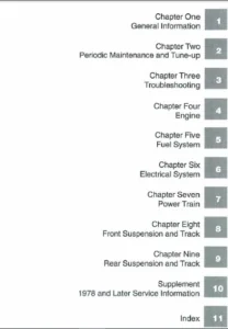
TABLE OF CONTENTS:
John Deere 655B and 755B Crawler Loader Repair Manual TM1478 – PDF DOWNLOAD
Contents 7
Introduction 4
General Information 11
Safety Information 13
Safety Signs 13
General Specifications 23
655B Crawler Loader Specifications 23
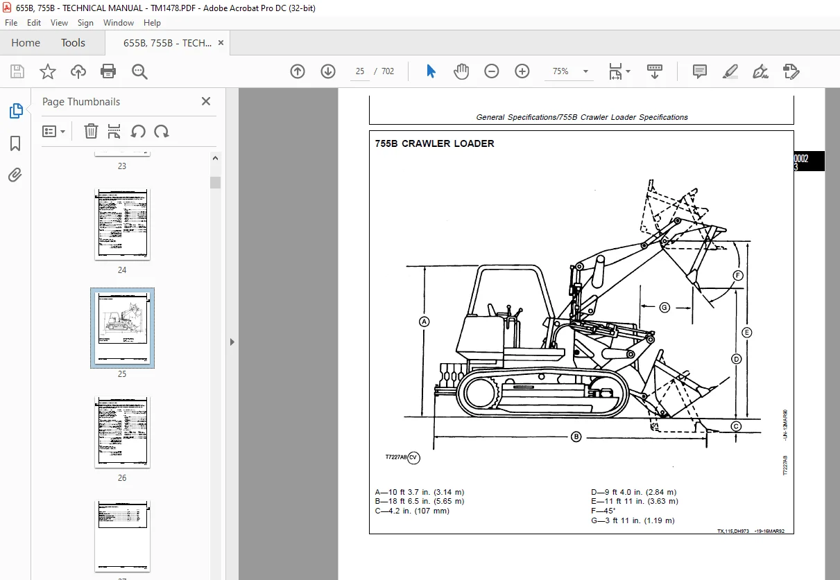
755B Crawler Loader Specifications 25
Capacities 27
Torque Values 29
Torque Values 29
Service Recommendations 33
O-Ring Boss Fittings 34
Flat Face O-Ring Seal Fittings 35
Straight or Tapered Fittings 36
Four-Bolt Flange Fittings 37
Track Shoe Bolt Torque 39
Master Link Track Shoe Bolt Torque 40
Fuels and Lubricants 43
Use Periodic Maintenance Chart 43
Fuel Specifications 43
Fuel Storage 43
Fuel Tank 44
Engine Oil 45
Hydraulic Oil 46
Splitter Gearbox Oil 46
Transmission Oil 47
Final Drive Oil 48
Roller and Idler Oil 48
Grease 49
Winch Oil 50
Engine Coolant 51
Alternative and Synthetic Lubricants 51
Lubricant Storage 51
Tracks 53
Track System 55
Essential Tools 55
Service Equipment and Tools 56
Other Materials 56
Specifications 57
Rock Guards and Track Guides 61
Remove and Install 61
Carrier Roller 62
Measure Wear 62
Remove and Install 62
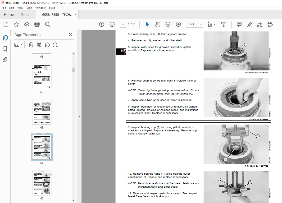
Disassemble 63
Assemble 65
Leakage Test 69
Track Roller 70
Measure Wear 70
Remove and Install 71
Disassemble 72
Cross Section 74
Assemble 75
Leakage Test 80
Track Shoes 80
Measure Grouser Wear 80
Remove and Install 82
Non-Lubricated Track Chain 84
Measure Track Pitch 84
Measure Bushing Outside Diameter 85
Measure Link Height 86
Exploded View 86
Remove 87
Install 88
Turn Pins and Bushings 89
Disassemble and Assemble 89
Replace Broken Part 90
Track Adjuster and Recoil Spring 92
Exlploded View 92
Remove 93
Install 95
Disassemble and Assemble Recoil Spring 97
Disassemble and Assemble Adjuster Cylinder 98
Track Frame100
Remove and Install100
Weld Track Frame101
Remove and Install Inner Guide Wear Strip102
Remove and Install Upper Wear Strip103
Remove and Install Lower Wear Strip105
Remove and Install Wear Strip Bar106
Front Idler108
Measure Wear108
Remove and Install109
Disassemble110
Inspect Metal Face Seals111
Exploded View112
Assemble113
Leakage Test118
Vertical Adjustment119
Horizontal Adjustment120
Sprocket120
Measure Wear120
Remove and Install121
Lubricated Track Chain122
Measure Link Height122
Measure Bushing Outside Diameter123
Measure Track Pitch124
Remove and Install124
Disassemble to Turn Bushing and Relubricate128
Assemble to Turn Bushing and Relubricate130
Turn Pins and Bushings and Not Relubricate137
Track Sag142
Adjustment142
Axles and Suspension Systems143
Drive Axle Housing and Support145
Essential Tools145
Other Material145
Specifications146
Drive Axle Housing and Support146
Remove146
Install150
Axle Shaft, Bearings and Reduction Gears153
Other Material153
Specifications154
Planetary Housing155
Remove and Install155
Planetary Housing and Final Drive158
Exploded View158
Disassemble and Assemble159
Final Drive and Sprocket Frame161
Remove and Install161
Metal Face Seals165
Inspect165
Final Drive and Sprocket Frame166
Disassemble166
Assemble167
Transmission171
Removal and Installation173
Essential Tools173
Other Material173
Specifications173
Hydrostatic Transmission174
Remove174
Install175
Hydrostatic Pump178
Remove178
Install180
Controls Linkage183
Service Equipment and Tools183
Other Material183
Specifications184
Steering Linkage185
Remove and Install185
Lower Steering Linkage188
Disassemble and Assemble (SN -731273)188
Disassemble and Assemble (SN731274- )190
Steering Linkage (SN -731273)192
Adjustment192
Steering Linkage (SN731274- )194
Adjustment194
Steering Pedals195
Remove and Install195
Control Head199
Remove and Install199
Disassemble and Assemble200
FNR Speed Control Head (SN -731273)202
Disassemble and Assemble202
FNR Speed Control Head (SN731274- )204
Disassemble and Assemble204
Neutral Lock (SN -731273)205
Remove and Install205
Neutral Lock (SN731274- )206
Remove and Install206
Return-to-Neutral Linkage (SN -731273)207
Remove and Install207
Return-to-Neutral Linkage (SN731274- )208
Remove and Install208
Speed Control Support209
Remove and Install209
Disassemble and Assemble209
Transmission Control Valve Linkage210
Remove and Install210
Input Drive Shafts And U-Joints211
Input Drive Shafts212
Remove and Install212
Disassemble and Assemble213
Hydraulic System (Hydrostatic Transmission)215
Essential Tools215
Service Equipment and Tools216
Other Material217
Specifications218
Hydrostatic Pump223
Disassemble223
Inspect235
Assemble238
Charge Pump – (SN -731273)251
Remove and Install251
Disassemble and Assemble252
Charge Pump – (SN731274- )253
Remove and Install253
Disassemble and Assemble (SN731274-757029)254
Disassemble and Assemble (SN757029- )256
Control Pump (SN731274- )257
Remove and Install257
Disassemble and Assemble258
Neutral Charge Relief Valve Housing (SN731274- )259
Disassemble and Assemble259
Pump Displacement Control Valve (PDCV)260
Remove and Install260
Disassemble261
Assemble266
Bypass Valve273
Remove and Install273
Disassemble and Assemble274
Hydrostatic Motor276
Disassemble276
Inspect289
Assemble292
Motor Displacement Control Valve (MDCV)305
Remove and Install305
Disassemble306
Assemble311
Manifold Valve317
Remove and Install317
Inspect319
Disassemble321
Assemble323
Transmission Control Valve325
Remove and Install325
Identification326
Disassemble P1 Over-Pressure Relief Valve328
Disassemble P2 Pressure Regulator Valve328
Disassemble Automatic Shut-Off Valve329
Disassemble Automatic Control Valve329
Disassemble Steering Valve Orifice331
Disassemble Automatic Control Valve Variable Orifice331
Disassemble Housing332
Disassemble Steering Valve – Bolt-On Lever Housing332
Disassemble Steering Valve – Screw-In Lever Housing334
Disassemble FNR Valve335
Disassemble Speed Control Valve336
Assemble Speed Control Valve337
Assemble FNR Valve338
Assemble Steering Valve – Bolt-On Lever Housing339
Assemble Steering Valve – Screw-In Lever Housing340
Assemble Housing341
Assemble Automatic Control Valve Variable Orifice342
Assemble Steering Valve Orifice343
Assemble Automatic Control Valve343
Assemble Automatic Shut-Off Valve345
Assemble P2 Pressure Regulator Valve346
Assemble P1 Over-Pressure Relief Valve346
Speed Control Valve Shim Pack Adjustment347
Oil Cooler347
Remove and Install347
Oil Cooler Bypass Valve348
Remove and Install348
Disassemble and Assemble349
Transmission Operating Pressure Valve (SN -731273)350
Remove and Install350
Disassemble and Assemble351
Hydrostatic Reservoir352
Remove and Install (SN -731273)352
Remove and Install (SN731274- )354
Transmission Filters355
Remove and Install (SN -731273)355
Remove and Install (SN731274- )356
Transmission Filter (SN731274- )360
Replace Element360
Engine363
Removal and Installation365
6414 John Deere Engine Repair365
6068T John Deere Engine Repair365
Electronic Fuel Injection System365
Special or Essential Tools365
Service Equipment and Tools367
Other Material367
Specifications368
Engine370
Remove and Install370
Oil Pan374
Remove and Install374
Stanadyne DM4 Fuel Injection Pump374
Remove374
Repair376
Install376
Stanadyne DB4 Fuel Injection Pump377
Remove377
Inspect Gear and Shaft381
Repair382
Install383
Injection Pump Timing386
Fuel Injection Nozzles386
Remove386
Install388
Bleed Fuel System389
Turbocharger391
Remove and Install391
Water Pump393
Remove and Install393
Thermostats395
Remove and Install395
Fuel Transfer Pump397
Remove and Install397
Fan Belt Tightener399
Remove, Disassemble, Assemble and Install399
Engine Auxiliary System401
Cold Weather Starting Aids403
Other Material403
Specifications403
Starting Aid Fluid Switch403
Remove and Install403
Starting Aid Solenoid404
Remove and Install404
Starting Aid Nozzle404
Remove and Install404
Engine Coolant Heater405
Remove and Install405
Cooling Systems407
Specifications407
Coolant Recovery Bottle408
Remove and Install408
Radiator and Oil Cooler (SN 751229)409
Remove and Install409
Disassemble and Assemble Radiator412
Radiator and Oil Cooler (SN751230- )413
Remove and Install413
Disassemble and Assemble Radiator416
Speed Controls417
Specifications417
Speed Control and Return-To-Neutral Linkage417
(SN -731273)417
(SN731274- )418
Engine Speed Control Linkage419
Remove and Install419
Automatic Control Valve Shut-Off Valve Linkage420
Remove and Install420
Intake System421
Special or Essential Tools421
Service Equipment and Tools421
Other Material421
Specifications422
Air Filter Elements422
Remove and Install422
Clean Dusty Element424
Clean Oily or Sooty Element424
Inspect425
Air Cleaner426
Remove and Install426
Test Air Intake System for Leaks427
External Exhaust System429
Specifications429
Muffler and Collar430
Remove and Install430
External Exhaust Supply System431
Other Material431
Specifications431
Fuel Tank Outlet Screen431
Remove and Install431
Fuel Tank432
Remove and Install432
Clutch (Cold Weather Disconnect)435
Controls Linkage437
Specifications437
Cold Weather Disconnect Linkage438
Remove and Install438
Elements439
Service Equipment and Tools439
Other Material439
Specifications439
Cold Weather Disconnect440
Remove and Install440
Pilot Bearing442
Remove and Install442
Connector Disk443
Remove and Install443
Splitter Drive445
Gears, Shafts and Bearings447
Service Equipment and Tools447
Other Material447
Specifications448
Splitter Housing449
Remove and Install449
Cross Section450
Disassemble and Assemble451
Park Brake457
Removal and Installation459
Park Brake459
Remove and Install459
Active Elements461
Service Equipment and Tools461
Other Material461
Specifications461
Park Brake462
Disassemble and Assemble462
Controls Linkage467
Specifications467
Park Brake Pedal Linkage468
Remove and Install (SN -731273)468
Remove and Install (SN731274- )469
Park Brake Valve Cable469
Remove and Install469
Park Brake Pedal470
Remove and Install470
Hydraulic System475
Specifications475
Park Brake Valve476
Remove and Install476
Disassemble and Assemble477
Equipment Attaching479
Drawbar481
Specifications481
Drawbar481
Remove and Install481
Towbar483
Specifications483
Pull Hook483
Remove and Install483
Electrical System485
Batteries, Support and Cables487
Specifications487
Batteries488
Battery Safety488
Check Electrolyte Level and Terminals489
Procedure for Testing490
Remove and Install491
Alternator, Regulator and Charging System Wiring493
Electronic Fuel and Injection System – Use CTM68493
Starting Motor and Actuators – Use CTM77493
Service Equipment and Tools493
Specifications494
Alternator495
Remove and Install (SN -791377)495
Remove and Install (SN791378- )496
Lighting System497
Other Materials497
Light Switch497
Remove and Install497
Work Lights497
Remove and Install Halogen Bulbs497
Adjustment499
Wiring Harness and Switches501
Special or Essential Tools501
Specifications501
Deutsch™ Connectors502
Replace502
Install Contact503
Weather Pack™ Connector504
Replace504
Install Contact505
Blade Terminals506
Battery Disconnect Switch507
Remove and Install507
Start Circuit Relay507
Remove and Install507
Key Switch508
Remove and Install508
Neutral Start Switch508
Remove and Install (SN -731273)508
Remove and Install (SN731274- )509
Fuses, AC Pressurizer, Dome Light, Rear Wiper509
Remove and Install509
Front Wiper Fuse510
Remove and Install510
Cab Relay510
Remove and Install (SN -741213)510
Remove and Install (SN741214- )511
Accessory Relay511
Remove and Install511
Circuit Breakers512
Remove and Install512
Switches, Start, Start Aid, Horn512
Remove and Install512
Ground Cables513
Remove and Install513
Front Wiper Switch514
Remove and Install514
Rear Wiper Switch514
Remove and Install514
System Controls515
Return-To-Dig Switch (SN -745056)515
Remove and Install515
Return-To-Dig Diode (SN -745056)515
Remove and Install515
Return-To-Dig Harness 655B – (SN745057- ) 755B – (SN745104- )516
Remove and Install516
Return-To-Dig Switch 655B – (SN745057- ) 755B – (SN745104- )517
Remove and Install517
Return-To-Dig Switch 655B – (SN745057- ) 755B – (SN745104- )518
Adjustment518
Instruments and Indicators519
Other Material519
Specifications519
Hour Meter Relay519
Remove and Install519
Indicator Lights and Hour Meter Relay Diodes520
Remove and Install520
Volt or Hour Meter520
Remove and Install520
Indicator Lights521
Remove and Install521
Transmission Oil Filter Restriction Indicator Switch521
Remove and Install (SN -731273)521
Remove and Install (SN731274- )522
Hydraulic Oil Filter Restriction Indicator Switch522
Remove and Install522
Transmission Oil Temperature Gauge Sender522
Remove and Install (SN731274- )522
Test Indicator Engine Oil Pressure Switch523
Remove and Install523
Engine Oil Pressure Gauge Sender523
Remove and Install (SN731274- )523
Pressure Gauges524
Remove and Install524
Motors and Actuators525
Specifications525
Starting Motor525
Starting Motor and Actuators – Use CTM77525
Remove and Install526
Frame, Chassis or Supporting Structure527
Frame Installation529
Welding Repair of Major Structures529
Frame Bottom Guards531
Front Bottom Guard531
Remove and Install531
Center Bottom Guard531
Remove and Install531
Rear Bottom Guard531
Remove and Install531
Chassis Weights533
Counterweight533
Remove and Install533
Operator’s Station535
Removal and Installation537
Service Equipment and Tools537
Specifications537
Cab538
Tilt or Remove and Install538
Operator Enclosure543
Special or Essential Tools543
Specifications543
Roll-Over Protective Structure Without Cab544
Remove and Install544
Windowpane and Molding545
Remove and Install545
Clean546
Dimensions547
Front Windshield Wiper Blade Assembly550
Remove and Install550
Front Windshield Wiper Motor551
Remove and Install551
Rear Wiper Motor552
Remove and Install552
Seat and Seat Belt553
Specifications553
Seat553
Remove and Install553
Disassemble and Assemble554
Heating and Air Conditioning561
Service Equipment and Tools561
Other Material561
Specifications562
Hose and Tubing Flare Connection Torques563
Hose and Tubing O-Ring Connections Torques563
Air Conditioning System564
Proper Refrigerant Handling564
Refrigerant Cautions564
Hoses and Tubing Inspection565
Leak Testing565
Servicing565
Compressor566
Remove and Install566
Compressor – R12567
Make Volumetric Efficiency Test567
Test Shaft Seal for Leaks568
Disassemble568
Assemble573
Compressor – R134a578
Disassemble and Assemble Compressor Clutch578
Check Clutch Hub Clearance579
Inspect Manifold579
Disassemble, Inspect and Assemble580
Condenser582
Remove and Install582
Leak Test583
Receiver-Dryer584
Remove and Install584
Temperature Control Switch585
Remove and Install585
Expansion Valve586
Remove and Install586
High and Low Pressure Switches587
Remove and Install587
Condenser Fan Motor587
Remove and Install587
Evaporator588
Remove588
Install589
Blower Motor590
Remove and Install590
Blower Switch590
Remove and Install590
Heater591
Remove and Install591
Sheet Metal and Styling593
Hood or Engine Enclosure595
Other Material595
Specifications595
Hood596
Remove and Install596
Cowl596
Remove and Install596
Engine Side Shields597
Remove and Install597
Grille and Grille Housing599
Other Material599
Specifications599
Grille Housing600
Remove and Install600
Disassemble601
Safety, Convenience and Miscellaneous603
Fire Extinguisher605
Fire Extinguisher605
Inspect605
Test605
Horn and Warning Devices607
Horn607
Remove and Install607
Reverse Warning Alarm607
Remove and Install607
Reverse Warning Alarm Switch608
Remove and Install608
Cigar Lighter609
Cigar Lighter or Resistor609
Remove and Install609
Loader611
Bucket613
Service Equipment and Tools613
Specifications613
Bucket614
Remove and Install614
Multi-Purpose Bucket616
Disassemble and Assemble616
General Purpose Bucket617
Disassemble and Assemble617
Bucket Tooth Tips618
Remove and Install618
Bucket Tooth Shanks618
Remove and Install618
Replace Cutting Edge620
Controls Linkage623
Other Material623
Control Linkage623
Remove and Install623
Frames625
Specifications625
Welding Repair of Major Structures626
Loader Boom627
Remove and Install627
Disassemble and Assemble628
Hydraulic System629
Essential Tools629
Service Equipment and Tools629
Other Material630
Specifications631
Hydraulic Pump (SN -742641)635
Remove and Install635
Disassemble636
Assemble638
Hydraulic Pump (SN742642- )639
Remove and Install639
Disassemble and Inspect640
Assemble640
Hydraulic Reservoir642
Remove and Install642
Hydraulic Oil Filter643
Remove and Install643
Control Valve644
Remove and Install644
Disassemble and Assemble (SN -733242)646
Boom Section646
Cross Section646
Disassemble and Assemble647
Bucket Section648
Cross Section648
Disassemble and Assemble649
Auxiliary Section650
Cross Section650
Disassemble and Assemble651
Disassemble and Assemble Monoblock 652
655B (SN733243-761834) 755B (SN733243-761920)652
System Relief Valve657
Circuit Relief Valve658
Circuit Relief Valve w/ Anticavitation659
655B (761835- ) 755B (761921- )662
System Relief Valve664
Circuit Relief Valve665
Boom Cylinder665
Remove and Install665
Bucket Cylinder668
Remove and Install668
Multi-Purpose Bucket Clam Cylinder670
Remove and Install670
Boom, Bucket or Clam Cylinders672
Disassemble672
Assemble677
Selector Valve680
Remove and Install680
Disassemble and Assemble681
Cushion Valve684
Remove and Install684
Disassemble and Assemble685
Dealer Fabricated Tools687
Dealer Fabricated Tools689
DSD301183 Special Spacer – 655B689
DSD311183 Special Spacer – 755B689
DSD140284 Hydrostatic Transmission Pump Repair Stand690
DSD130284 Hydrostatic Transmission Motor Repair Stand691
JT38032 Driver692
JT38035 Driver692
JT38039 Driver692
JT38040 Driver692
JT38041 Driver693
JT38043 Cardboard Template – 655B693
JT38044 Cardboard Template – 755B694
DF1041 Track Nut Removal Tool695
Liner Holding Tool696
DFT1078 Final Drive Lifting Fixture697
DFT1079 Adapter698
Index699
S.M 4/1/25