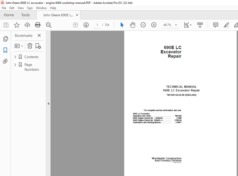
John Deere 690E LC Excavator Repair Technical Manual – PDF DOWNLOAD
Original price was: $89.95.$28.95Current price is: $28.95.
John Deere 690E LC Excavator Repair Technical Manual – PDF DOWNLOAD
Description
John Deere 690E LC Excavator Repair Technical Manual – PDF DOWNLOAD
DESCRIPTION:
John Deere 690E LC Excavator Repair Technical Manual – PDF DOWNLOAD
For complete service information also see:
690E LC Excavator
Operation and Tests . . . . . . . . . . . . . . . . . . . TM1508
6068 Engine (Serial No. —559602) . . . . . . . . CTM8
6068 Engine (Serial No. 559603—) . . . . . . . . CTM104
Alternators and Starting Motors. . . . . . . . . . CTM77
Foreword :
This manual is written for an experienced technician. Essential tools required in performing certain service work are identified in this manual and are recommended for use. Live with safety: Read the safety messages in the introduction of this manual and the cautions presented throughout the text of the manual.
- This is the safety-alert symbol. When you see this symbol on the machine or in this manual, be alert to the potential for personal injury. Technical manuals are divided in two parts: repair and operation and tests. Repair sections tell how to repair the components. Operation and tests sections help you identify the majority of routine failures quickly.
- Information is organized in groups for the various components requiring service instruction. At the beginning of each group are summary listings of all applicable essential tools, service equipment and tools, other materials needed to do the job, service parts kits, specifications, wear tolerances, and torque values.
- Technical Manuals are concise guides for specific machines. They are on-the-job guides containing only the vital information needed for diagnosis, analysis, testing, and repair. Fundamental service information is available from other sources covering basic theory of operation, fundamentals of troubleshooting, general maintenance, and basic type of failures and their causes.
TABLE OF CONTENTS:
John Deere 690E LC Excavator Repair Technical Manual – PDF DOWNLOAD
Contents……………………………………………………………………………. 5
General Information………………………………………………………………. 9
Safety………………………………………………………………………. 11
Follow Safe Procedures…………………………………………………….. 11
Prepare for Emergencies……………………………………………………. 11
Prevent Acid Burns………………………………………………………… 12
Handle Chemical Products Safely…………………………………………….. 13
Handle Fluids Safely—Avoid Fires……………………………………………. 13
Avoid High-Pressure Fluids…………………………………………………. 14
Warn Others of Service Work………………………………………………… 14
Support Machine Properly…………………………………………………… 15
Operate Only from Operator’s Seat…………………………………………… 15
Park Machine Safely……………………………………………………….. 15
Stay Clear of Moving Parts…………………………………………………. 16
Avoid Power Lines…………………………………………………………. 16
Use Handholds and Steps……………………………………………………. 16
Keep Riders Off Machine……………………………………………………. 17
Move and Operate Machine Safely…………………………………………….. 17
Wear Protective Clothing…………………………………………………… 17
Protect Against Flying Debris………………………………………………. 18
Protect Against Noise……………………………………………………… 18
Illuminate Work Area Safely………………………………………………… 18
Service Machines Safely……………………………………………………. 18
Remove Paint Before Welding or Heating………………………………………. 19
Avoid Heating Near Pressurized Fluid Lines…………………………………… 19
Beware of Exhaust Fumes……………………………………………………. 19
Use Proper Lifting Equipment……………………………………………….. 20
Service Cooling System Safely………………………………………………. 20
Dispose of Waste Properly………………………………………………….. 20
Work in a Clean Area………………………………………………………. 21
Use Tools Properly………………………………………………………… 21
Replace Safety Signs………………………………………………………. 21
Live With Safety………………………………………………………….. 22
General Specifications………………………………………………………… 23
690E LC………………………………………………………………….. 23
690E LC Long Front Specifications…………………………………………… 25
690E LC And 690E LC Long Front Drain And Refill Capacities…………………….. 26
Torque Values………………………………………………………………… 27
Unified Inch Bolt and Cap Screw Torque Values………………………………… 27
Metric Bolt and Cap Screw Torque Values……………………………………… 28
Additional Metric Cap Screw Torque Values……………………………………. 29
Service Recommendations for O-Ring Boss Fittings……………………………… 30
Service Recommendations for Flat Face O-Ring Seal Fittings…………………….. 32
Service Recommendations for 37° Flare and 30° Cone Seat Connectors……………… 33
Service Recommendations For Flared Connections—Straight or Tapered Threads………. 34
Service Recommendations For Inch Series Four Bolt Flange Fittings………………. 35
Service Recommendations for Metric Series Four Bolt Flange Fitting……………… 36
Fuels And Lubricants………………………………………………………….. 37
Diesel Fuel………………………………………………………………. 37
Do Not Use Galvanized Containers……………………………………………. 37
Storing Fuel……………………………………………………………… 38
Low Sulfur Diesel Fuel Conditioner………………………………………….. 38
Fuel Tank………………………………………………………………… 39
Diesel Engine Oil…………………………………………………………. 40
Hydraulic Oil…………………………………………………………….. 41
Propel Gearbox Oil………………………………………………………… 42
Track Roller, Front Idler, And Carrier Roller Oil…………………………….. 42
Track Adjuster, Working Tool Pivot, Swing Bearing, And Swing Bearing Gear Grease…. 43
Oil Filters………………………………………………………………. 43
Lubricant Storage…………………………………………………………. 44
Alternative and Synthetic Lubricants………………………………………… 44
Mixing of Lubricants………………………………………………………. 45
Tracks………………………………………………………………………….. 47
Track System…………………………………………………………………. 49
Service Equipment And Tools………………………………………………… 49
Other Material……………………………………………………………. 51
Specifications……………………………………………………………. 52
Track Guide………………………………………………………………. 54
Remove and Install…………………………………………………….. 54
Lower Track Roller………………………………………………………… 56
Measure Wear………………………………………………………….. 56
Remove and Install…………………………………………………….. 57
Disassemble and Assemble……………………………………………….. 59
Test for Oil Leakage…………………………………………………… 63
Metal Face Seals………………………………………………………….. 64
Inspect………………………………………………………………. 64
Upper Track Roller………………………………………………………… 65
Measure Wear………………………………………………………….. 65
Remove and Install…………………………………………………….. 66
Disassemble and Assemble……………………………………………….. 67
Track Shoe……………………………………………………………….. 70
Measure Grouser Wear…………………………………………………… 70
Remove and Install…………………………………………………….. 71
Track Chain………………………………………………………………. 72
Measure Wear………………………………………………………….. 72
Measure Track Chain Bushing Wear……………………………………………. 73
Measure Track Chain Pitch………………………………………………….. 74
Track Chain………………………………………………………………. 75
Remove……………………………………………………………….. 75
Install………………………………………………………………. 77
Disassemble and Assemble……………………………………………….. 78
Disassemble and Assemble to Replace Broken Part…………………………… 78
Track Sag………………………………………………………………… 80
Measure and Adjust…………………………………………………….. 80
Sprocket…………………………………………………………………. 82
Remove and Install…………………………………………………….. 82
Front Idler………………………………………………………………. 84
Measure Wear………………………………………………………….. 84
Remove and Install…………………………………………………….. 85
Disassemble…………………………………………………………… 87
Assemble……………………………………………………………… 88
Test for Oil Leakage…………………………………………………… 90
Track Adjuster Cylinder and Recoil Spring……………………………………. 91
Remove and Install…………………………………………………….. 91
Recoil Spring…………………………………………………………….. 92
Disassemble and Assemble……………………………………………….. 92
Track Adjuster Cylinder……………………………………………………. 95
Disassemble and Assemble……………………………………………….. 95
Axles And Suspension Systems………………………………………………………. 97
Axle Shaft, Bearings, And Reduction Gears……………………………………….. 99
Special Or Essential Tools…………………………………………………. 99
Service Equipment And Tools………………………………………………… 99
Other Material…………………………………………………………….101
Specifications…………………………………………………………….102
Towing Machine…………………………………………………………….102
Propel Gearbox and Brake Elements……………………………………………104
Replace……………………………………………………………….104
Propel Gearbox and Brake……………………………………………………106
Remove and Install……………………………………………………..106
Propel Gearbox…………………………………………………………….113
Disassemble……………………………………………………………113
Metal Face Seals…………………………………………………………..120
Inspect……………………………………………………………….120
Propel Gearbox…………………………………………………………….122
Assemble………………………………………………………………122
Propel Gearbox and Brake……………………………………………………130
Assemble Replacement Housing and Bearing Assembly………………………….130
Hydraulic System………………………………………………………………131
Service Equipment And Tools…………………………………………………131
Other Material…………………………………………………………….132
Specifications…………………………………………………………….133
Propel Motor………………………………………………………………133
Remove and Install……………………………………………………..133
Start-Up Procedure……………………………………………………..136
Disassemble……………………………………………………………138
Valve Housing and Cover…………………………………………………….144
Disassemble……………………………………………………………144
Propel Motor………………………………………………………………146
Assemble………………………………………………………………146
Counterbalance Valve……………………………………………………….154
Remove and Install……………………………………………………..154
Disassemble and Assemble………………………………………………..155
Supply Shuttle Valve……………………………………………………….156
Remove and Install……………………………………………………..156
Crossover Relief Valve……………………………………………………..158
Remove and Install……………………………………………………..158
Shuttle Valve……………………………………………………………..160
Remove and Install……………………………………………………..160
Low Speed Selector Valve……………………………………………………161
Remove and Install……………………………………………………..161
Brake Release Pressure Reducing Valve………………………………………..162
Remove and Install……………………………………………………..162
Propel Hydraulic Lines……………………………………………………..162
Remove and Install……………………………………………………..162
Rotary Manifold……………………………………………………………163
Remove and Install……………………………………………………..163
Disassemble and Assemble………………………………………………..168
Air Test………………………………………………………………169
Propel Speed Change Solenoid Valve…………………………………………..170
Remove and Install……………………………………………………..170
Disassemble and Assemble………………………………………………..173
Engine…………………………………………………………………………..175
Removal And Installation……………………………………………………….177
6068 John Deere Engine—Use CTM8……………………………………………..177
6068 John Deere Engine—Use CTM104……………………………………………177
Special Or Essential Tools………………………………………………….177
Service Equipment And Tools…………………………………………………181
Other Material…………………………………………………………….182
Specifications…………………………………………………………….183
Engine (SN -559602)………………………………………………………..185
Remove and Install……………………………………………………..185
Engine (SN 559603-)………………………………………………………..192
Remove and Install……………………………………………………..192
Oil Pan…………………………………………………………………..201
Remove and Install……………………………………………………..201
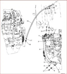
Fuel Injection Nozzles……………………………………………………..202
Remove and Install……………………………………………………..202
Injection Nozzle Bores……………………………………………………..205
Clean…………………………………………………………………205
DB4 Fuel Injection Pump (SN -559602)…………………………………………205
Remove………………………………………………………………..205
Install……………………………………………………………….208
DB4 Fuel Injection Pump (SN 559603-)…………………………………………211
Remove and Install……………………………………………………..211
JT07158 TIME TRAC Installation………………………………………………212
Fuel Filter (SN -559602)……………………………………………………213
Change………………………………………………………………..213
Final Fuel Filter (SN 559603-)………………………………………………213
Change………………………………………………………………..213
Primary Fuel Filter/Water Separator (SN 559603-)………………………………214
Change………………………………………………………………..214
Fuel Transfer Pump (SN -559602)……………………………………………..216
Remove and Install……………………………………………………..216
Fuel Transfer Pump (SN 559603-)……………………………………………..217
Remove and Install……………………………………………………..217
Fuel System (SN -559602)……………………………………………………218
Bleed…………………………………………………………………218
Fuel System (SN 559603-)……………………………………………………218
Bleed…………………………………………………………………218
Water Pump (SN -559602)…………………………………………………….219
Remove and Install……………………………………………………..219
Water Pump (SN 559603-)…………………………………………………….223
Remove and Install……………………………………………………..223
Thermostat (SN -559602)…………………………………………………….227
Remove and Install……………………………………………………..227
Thermostat (SN 559603-)…………………………………………………….229
Remove and Install……………………………………………………..229
Intake Manifold Tube (SN -559602)……………………………………………231
Remove and Install……………………………………………………..231
Intake Manifold Tube (SN 559603-)……………………………………………232
Remove and Install……………………………………………………..232
Exhaust Manifold (SN -559602)……………………………………………….233
Remove and Install……………………………………………………..233
Exhaust Manifold (SN 559603-)……………………………………………….235
Remove and Install……………………………………………………..235
Turbocharger (SN -559602)…………………………………………………..237
Remove and Install……………………………………………………..237
Turbocharger (SN 559603-)…………………………………………………..239
Remove and Install……………………………………………………..239
Oil Cooler (SN -559602)…………………………………………………….240
Remove and Install……………………………………………………..240
Oil Cooler (SN 559603-)…………………………………………………….241
Remove and Install……………………………………………………..241
Engine Valve Lash (Clearance) (SN -559602)……………………………………242
Check and Adjust……………………………………………………….242
Engine Valve Lash (Clearance) (SN 559603-)……………………………………244
Check and Adjust……………………………………………………….244
Starter (SN -559602)……………………………………………………….247
Remove and Install……………………………………………………..247
Starter (SN 559603-)……………………………………………………….248
Remove and Install……………………………………………………..248
Engine Auxiliary System……………………………………………………………249
Cold Weather Starting Aids……………………………………………………..251
Other Material…………………………………………………………….251
Specifications…………………………………………………………….251
Starting Aid Solenoid and Nozzle…………………………………………….252
Remove and Install……………………………………………………..252
Engine Coolant Heater………………………………………………………252
Remove and Install……………………………………………………..252
Cooling System………………………………………………………………..255
Specifications…………………………………………………………….255
Fan, Guards, and Shroud (SN -559602)…………………………………………256
Remove and Install……………………………………………………..256
Fan, Guards, and Shroud (SN 559603-)…………………………………………258
Remove and Install……………………………………………………..258
Radiator………………………………………………………………….260
Remove and Install……………………………………………………..260
Serpentine Belt (SN -559602)………………………………………………..263
Inspect……………………………………………………………….263
Serpentine Belt (SN 559603-)………………………………………………..264
Inspect……………………………………………………………….264
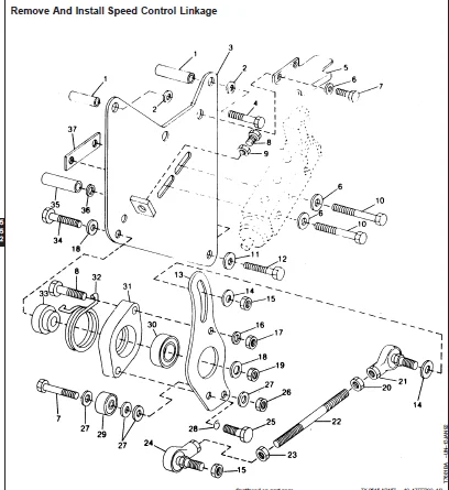
Speed Controls………………………………………………………………..265
Specifications…………………………………………………………….265
Speed Control Linkage………………………………………………………266
Remove and Install……………………………………………………..266
Adjust………………………………………………………………..267
Intake System…………………………………………………………………271
Special Or Essential Tools………………………………………………….271
Service Equipment And Tools…………………………………………………271
Specifications…………………………………………………………….272
Air Cleaner……………………………………………………………….273
Remove and Install……………………………………………………..273
Air Intake System………………………………………………………….274
Leakage Test…………………………………………………………..274
External Exhaust Systems……………………………………………………….275
Muffler…………………………………………………………………..275
Remove and Install……………………………………………………..275
External Fuel Supply Systems……………………………………………………277
Specifications…………………………………………………………….277
Other Material…………………………………………………………….277
Fuel Tank…………………………………………………………………278
Remove and Install……………………………………………………..278
Water Separator (SN -559602)………………………………………………..280
Remove and Install……………………………………………………..280
Primary Fuel Filter (Water Separator) (SN 559603-)…………………………….281
Remove and Install……………………………………………………..281
Water Separator Filter Element (SN -559602)…………………………………..281
Replace……………………………………………………………….281
Primary Fuel Filter (Water Separator) (SN 559603-)…………………………….282
Disassemble and Assemble………………………………………………..282
Dampener Drive (Flex Coupling)……………………………………………………..283
Elements……………………………………………………………………..285
Specifications…………………………………………………………….285
Dampener Drive (Flex Coupler) (SN -559602)……………………………………286
Remove and Install……………………………………………………..286
Dampener Drive (Flex Coupler) (SN 559603-)……………………………………288
Remove and Install……………………………………………………..288
Electrical System…………………………………………………………………291
Batteries, Support, And Cables………………………………………………….293
Service Equipment And Tools…………………………………………………293
Specifications…………………………………………………………….294
Handle Batteries Safely…………………………………………………….295
Procedure For Testing Batteries……………………………………………..296
Check Battery Electrolyte Specific Gravity……………………………………297
Check Battery Electrolyte Level And Terminals…………………………………298
Booster Batteries………………………………………………………….300
24-Volt System…………………………………………………………300
Batteries…………………………………………………………………302
Charge………………………………………………………………..302
Remove and Install……………………………………………………..303
Adding 12-Volt Accessories………………………………………………….304
Alternator, Regulator, And Charging Wiring……………………………………….305
Alternators And Starting Motors—Use CTM77…………………………………….305
Specifications…………………………………………………………….305
Alternator………………………………………………………………..306
Remove and Install (SN -541822)………………………………………….306
Remove and Install (SN 541823-)………………………………………….307
Remove and Install (SN 559603-)………………………………………….308
Lighting System……………………………………………………………….311
Halogen Bulbs……………………………………………………………..311
Replacing……………………………………………………………..311
Work Light………………………………………………………………..312
Adjustment…………………………………………………………….312
Fuses…………………………………………………………………….313
Replacing……………………………………………………………..313
Specifications…………………………………………………………314
Color Codes……………………………………………………………315
Wiring Harness And Switches…………………………………………………….317
Special Or Essential Tools………………………………………………….317
Vehicle Electrical Component Identification…………………………………..319
Engine Electrical Component Identification……………………………………321
Cab Electrical Component Identification………………………………………322
Starter Switch…………………………………………………………….323
Remove and Install……………………………………………………..323
Radio, Propel Alarm Cancel, and Start Aid Switches…………………………….324
Remove and Install……………………………………………………..324
Monitor Buzzer and Air Conditioner Switch…………………………………….326
Remove and Install……………………………………………………..326
DEUTSCH Connectors…………………………………………………………326
Replace……………………………………………………………….326
DEUTSCH Contact……………………………………………………………328
Install……………………………………………………………….328
WEATHER PACK Connector……………………………………………………..329
Replace……………………………………………………………….329
WEATHER PACK Contact……………………………………………………….330
Install……………………………………………………………….330
Remove Connector Body From Blade Terminals……………………………………331
System Controls……………………………………………………………….333
Welding On Machine…………………………………………………………333
System Controller………………………………………………………….334
Remove and Install……………………………………………………..334
Monitor Controller…………………………………………………………335
Remove and Install……………………………………………………..335
Instruments And Indicators……………………………………………………..337
Monitor Panel……………………………………………………………..337
Replace Bulbs………………………………………………………….337
Remove and Install……………………………………………………..337
Switch Panel 1…………………………………………………………….339
Remove and Install……………………………………………………..339
Hour Meter, Coolant Temperature and Fuel Level Gauges………………………340
Switch Panel 2…………………………………………………………….341
Replace Bulb…………………………………………………………..341
Remove and Install……………………………………………………..342
Frame Or Supporting Structure………………………………………………………345
Frame Installation…………………………………………………………….347
Specifications…………………………………………………………….347
Welding Repair Of Major Structure……………………………………………348
Chassis Weights……………………………………………………………….351
Service Equipment And Tools…………………………………………………351
Specifications…………………………………………………………….351
Other Material…………………………………………………………….352
Counterweight……………………………………………………………..353
Remove and Install……………………………………………………..353
Operator’s Station………………………………………………………………..355
Removal And Installation……………………………………………………….357
Specifications…………………………………………………………….357
Cab………………………………………………………………………357
Remove and Install……………………………………………………..357
Operator Enclosure…………………………………………………………….367
Service Equipment And Tools…………………………………………………367
Other Material…………………………………………………………….367
Windowpane and Molding, Two Piece……………………………………………367
Remove and Install……………………………………………………..367
Windowpane and Molding, One Piece……………………………………………368
Remove and Install……………………………………………………..368
Sliding Windows……………………………………………………………369
Remove and Install……………………………………………………..369
Windowpane Dimensions………………………………………………………370
Seat…………………………………………………………………………373
Seat (SN -538404)………………………………………………………….373
Remove and Install……………………………………………………..373
Seat (SN 538405-)………………………………………………………….374
Remove and Install……………………………………………………..374
Seat (SN 537781-538404)…………………………………………………….375
Disassemble and Assemble………………………………………………..375
Seat (SN 538405-549976)…………………………………………………….376
Disassemble and Assemble………………………………………………..376
Seat (SN 549977-)………………………………………………………….377
Disassemble and Assemble………………………………………………..377
Seat Stand (SN -547853)…………………………………………………….378
Disassemble and Assemble………………………………………………..378
Seat Stand (SN 547854-)…………………………………………………….380
Disassemble and Assemble………………………………………………..380
Heating And Air Conditioning……………………………………………………383
Special Or Essential Tools………………………………………………….383
Service Equipment And Tools…………………………………………………384
Other Material…………………………………………………………….385
Specifications…………………………………………………………….386
Blower Motor………………………………………………………………387
Remove and Install……………………………………………………..387
Heater Core and Blower Motor Relay…………………………………………..388
Remove and Install……………………………………………………..388
Heater Control…………………………………………………………….389
Remove and Install……………………………………………………..389
Refrigerant (R-12) Cautions (SN -541550)……………………………………..390
Compressor Oil (SN -541550)…………………………………………………391
Check and Add………………………………………………………….391
Air Conditioning Gauge Set (SN -541550)………………………………………392
Installation Procedure …………………………………………………392
Refrigerant Recovery (SN -541550)……………………………………………393
Evacuate the System (SN -541550)…………………………………………….394
Charge the System (SN -541550)………………………………………………396
Add Refrigerant (SN -541550)………………………………………………..398
Compressor (SN -541550)…………………………………………………….399
Inspect Vee Belt, Check and Adjust Tension………………………………..399
Remove and Install……………………………………………………..400
Volumetric Efficiency Test-R12…………………………………………..401
Shaft Seal Leak Test……………………………………………………402
Disassemble and Inspect…………………………………………………404
Inspect Clutch Pulley, Bearing and Hub……………………………………408
Replace Clutch Pulley Bearing……………………………………………408
Replace Shaft Seal Seat…………………………………………………409
Assemble………………………………………………………………410
Leak Testing…………………………………………………………..413
Refrigerant Hoses and Tubing Inspection (SN -541550)…………………………..413
Condenser (SN -541550)……………………………………………………..414
Remove and Install……………………………………………………..414
Receiver/Dryer (SN -541550)…………………………………………………415
Remove and Install……………………………………………………..415
Expansion Valve (SN -541550)………………………………………………..415
Remove and Install……………………………………………………..415
Bench Test and Adjustment……………………………………………….416
Evaporator (SN -541550)…………………………………………………….417
Remove and Install……………………………………………………..417
Low and High Pressure Switches (SN -541550)…………………………………..418
Remove and Install……………………………………………………..418
Thermostat Switch, Air Conditioner and Compressor Relay (SN -541550)…………….419
Remove and Install……………………………………………………..419
Air Conditioning Switch (SN -541550)…………………………………………420
Remove and Install……………………………………………………..420
Safety And Convenience…………………………………………………………….421
Horn And Warning Devices……………………………………………………….423
Propel Alarm………………………………………………………………423
Remove and Install……………………………………………………..423
Changing Travel Alarm Volume………………………………………………..423
Excavator………………………………………………………………………..425
Bucket……………………………………………………………………….429
Specifications…………………………………………………………….429
Bucket Tooth Tip-Heavy-Duty Bucket…………………………………………..429
Replacing……………………………………………………………..429
Tooth Shank……………………………………………………………….430
Remove and Install……………………………………………………..430
Bucket and Linkage (SN -538759)……………………………………………..433
Remove and Install……………………………………………………..433
Bucket and Linkage (SN 538760-)……………………………………………..435
Remove and Install……………………………………………………..435
Bucket and Linkage…………………………………………………………436
Adjust………………………………………………………………..436
Cutting Edge………………………………………………………………438
Replace Welded…………………………………………………………438
Repair Cracked…………………………………………………………438
Frames……………………………………………………………………….439
Specifications…………………………………………………………….439
Other Material…………………………………………………………….439
Arm………………………………………………………………………440
Remove and Install……………………………………………………..440
Boom……………………………………………………………………..442
Remove and Install……………………………………………………..442
Bushings and Seals…………………………………………………………445
Remove and Install……………………………………………………..445
Hydraulic System………………………………………………………………447
Special Or Essential Tools………………………………………………….447
Service Equipment And Tools…………………………………………………448
Other Material…………………………………………………………….450
Specifications…………………………………………………………….451
Lower Boom With Engine Stopped………………………………………………459
Raise Boom With Engine Stopped………………………………………………461
Swing Upperstructure With Engine Stopped……………………………………..464
Hydraulic Oil Cleanup Procedure……………………………………………..467
Hydraulic Pump (SN -559602)…………………………………………………469
Remove and Install……………………………………………………..469
Hydraulic Pump (SN 559603-)…………………………………………………471
Remove and Install……………………………………………………..471
Hydraulic Pump…………………………………………………………….474
Start-Up Procedure……………………………………………………..474
Hydraulic Pump (SN -559602)…………………………………………………476
Disassemble……………………………………………………………476
Hydraulic Pump…………………………………………………………….484
Inspect……………………………………………………………….484
Hydraulic Pump (SN -559602)…………………………………………………487
Assemble………………………………………………………………487
Hydraulic Pump (SN 559603-)…………………………………………………498
Disassemble and Assemble………………………………………………..498
Pump Displacement Solenoid Valve (SN -559602)…………………………………498
Remove and Install……………………………………………………..498
Pump Displacement Solenoid Valve (SN 559603-)…………………………………499
Remove and Install……………………………………………………..499
Pump Displacement Solenoid Valve (SN -559602)…………………………………500
Disassemble and Assemble………………………………………………..500
Pump Displacement Solenoid Valve (SN 559603-)…………………………………501
Disassemble and Assemble………………………………………………..501
Load Sense Valve (SN -559602)……………………………………………….502
Remove and Install……………………………………………………..502
Load Sense Valve (SN 559603-)……………………………………………….503
Remove and Install……………………………………………………..503
Load Sense Valve (SN -559602)……………………………………………….504
Disassemble and Assemble………………………………………………..504
Load Sense Valve (SN 559603-)……………………………………………….505
Disassemble and Assemble………………………………………………..505
Pilot Pump………………………………………………………………..506
Remove and Install……………………………………………………..506
Disassemble and Assemble………………………………………………..506
Pilot Filter………………………………………………………………508
Remove and Install……………………………………………………..508
Hydraulic Oil Filter……………………………………………………….509
Inspect……………………………………………………………….509
Pilot Shut-Off Valve……………………………………………………….510
Remove and Install……………………………………………………..510
Disassemble and Assemble………………………………………………..511
Linkage Adjustment……………………………………………………..512
Dig Function Pilot Controller……………………………………………….514
Remove and Install……………………………………………………..514
Disassemble and Assemble………………………………………………..516
Propel Pilot Controller (SN -547853)…………………………………………518
Remove and Install……………………………………………………..518
Propel Pilot Controller (SN -547854)…………………………………………519
Remove and Install……………………………………………………..519
Propel Pilot Controller…………………………………………………….522
Disassemble and Assemble………………………………………………..522
Dig Pilot Check Valve Block (SN 543990-559935)………………………………..527
Remove and Install……………………………………………………..527
Dig Pilot Check Valve Block (SN 559936-)……………………………………..528
Remove and Install……………………………………………………..528
Propel Pilot Check Valve Block………………………………………………529
Remove and Install……………………………………………………..529
Disassemble and Assemble………………………………………………..531
Hydraulic Control Valve (SN -556935)…………………………………………532
Remove and Install……………………………………………………..532
Boom, Arm, and Swing Control Valve Manifold (SN 556936-)……………………….543
Remove and Install……………………………………………………..543
Return Manifold (SN 556936-)………………………………………………..552
Remove and Install……………………………………………………..552
Oil Cooler Bypass Valve (SN 556936-)…………………………………………553
Remove and Install……………………………………………………..553
Arm Cylinder Restrictor (SN 546276-556935)……………………………………553
Remove and Install……………………………………………………..553
Arm and Boom Cylinder Restrictors (SN 556936-)………………………………..555
Remove and Install……………………………………………………..555
Anti-Cavitation Back Pressure Check Valve (SN -556935)…………………………555
Remove and Install……………………………………………………..555
Anti-Cavitation Back Pressure Check Valve (SN 556936-………………………….556
Remove and Install……………………………………………………..556
Combined Function Shuttle Valve (SN -556935)………………………………….558
Remove and Install……………………………………………………..558
Combined Function Shuttle Valve (SN 556936-)………………………………….558
Remove and Install……………………………………………………..558
Disassemble and Assemble………………………………………………..559
Pressure Control Manifold (SN -556935)……………………………………….560
Remove and Install……………………………………………………..560
Load Sense System Relief Valve (SN -556935)…………………………………..560
Disassemble and Assemble………………………………………………..560
Load Sense System Relief Valve (SN 556936-)…………………………………..561
Remove and Install……………………………………………………..561
Disassemble and Assemble………………………………………………..562
Safety Valve (SN -556935)…………………………………………………..563
Disassemble and Assemble………………………………………………..563
Pilot Pressure Regulating Valve (SN -556935)………………………………….563
Disassemble and Assemble………………………………………………..563
Pilot Pressure Regulating Valve (SN 556936-)………………………………….564
Remove and Install……………………………………………………..564
Disassemble and Assemble………………………………………………..564
Power Boost Solenoid Valve (SN -556935)………………………………………565
Remove and Install……………………………………………………..565
Power Boost Solenoid Valve (SN 556936-)………………………………………565
Remove and Install……………………………………………………..565
Circuit Relief and Anti-Cavitation Valves (SN -556935)…………………………566
Remove and Install……………………………………………………..566
Bucket Circuit Relief and Anti-Cavitation Valves (SN 556936-)…………………..567
Remove and Install……………………………………………………..567
Boom, Arm, and Bucket Valve Section (SN -556935)………………………………568
Disassemble and Assemble………………………………………………..568
Swing Valve Section………………………………………………………..573
Disassemble and Assemble………………………………………………..573
Propel Valve Section (SN -556935)……………………………………………578
Disassemble and Assemble………………………………………………..578
Boom, Arm, and Swing Control Valve (SN 556936-)……………………………….582
Disassemble and Assemble………………………………………………..582
Make-Up Valve (SN -556935)………………………………………………….582
Remove and Install……………………………………………………..582
Propel Circuit Make-Up Valve (SN 556936-)…………………………………….583
Remove and Install……………………………………………………..583
Auxiliary Valve Section (SN -556935)…………………………………………583
Disassemble and Assemble………………………………………………..583
Monoblock Control Valve (SN 556936-)…………………………………………584
Remove and Install……………………………………………………..584
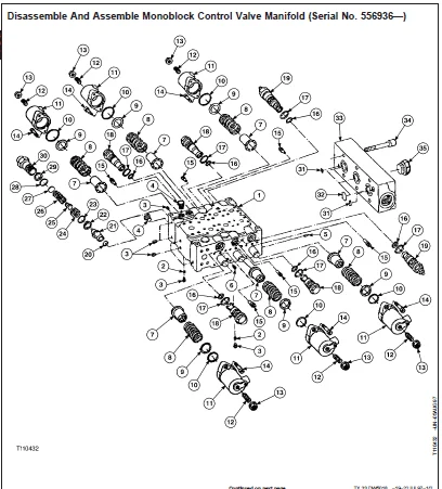
Monoblock Control Valve Manifold (SN 556936-)…………………………………588
Disassemble and Assemble………………………………………………..588
Safety Relief Valve (SN 556936-)…………………………………………….589
Remove and Install……………………………………………………..589
Disassemble and Assemble………………………………………………..590
Boom Regenerative Valve (SN 545157-556935)……………………………………591
Remove and Install……………………………………………………..591
Disassemble and Assemble………………………………………………..592
Arm Regenerative Valve (SN 546277-556935)…………………………………….593
Remove and Install……………………………………………………..593
Disassemble and Assemble………………………………………………..594
Arm Regenerative Poppet Valve (SN 556936-)……………………………………595
Remove and Install……………………………………………………..595
Arm Regenerative Valve (SN 556936-)………………………………………….596
Disassemble and Assemble………………………………………………..596
Stop Cushion Valve…………………………………………………………597
Remove and Install……………………………………………………..597
Swing Stop Cushion Valve (SN 546277-)………………………………………..598
Disassemble and Assemble………………………………………………..598
Swing Torque Control Valve (SN -556935)………………………………………599
Remove and Install……………………………………………………..599
Swing Torque Control Valve (SN 556936-)………………………………………600
Remove and Install……………………………………………………..600
Swing Torque Control Valve (SN -546276)………………………………………601
Disassemble and Assemble………………………………………………..601
Swing Torque Control Valve (SN 556936-)………………………………………602
Disassemble and Assemble………………………………………………..602
Boom and Arm Anti-Drift Valve (SN -556935)……………………………………602
Remove and Install……………………………………………………..602
Boom and Arm Anti Drift Valve (SN 556936-)……………………………………605
Remove and Install……………………………………………………..605
Boom and Arm Anti Drift Valve……………………………………………….607
Disassemble and Assemble………………………………………………..607
Dual Solenoid Block (SN -538538)…………………………………………….608
Remove and Install……………………………………………………..608
Dual Solenoid Block (SN 538539-)…………………………………………….609
Remove and Install……………………………………………………..609
Dual Solenoid Valve Block (SN 538539-)……………………………………….610
Disassemble and Assemble………………………………………………..610
Engine Speed Control Actuator……………………………………………….611
Remove and Install……………………………………………………..611
Disassemble and Assemble………………………………………………..612
Boom Cylinder……………………………………………………………..613
Remove and Install……………………………………………………..613
Arm Cylinder………………………………………………………………615
Remove and Install……………………………………………………..615
Bucket Cylinder……………………………………………………………617
Remove and Install……………………………………………………..617
Hydraulic Cylinder Bleed Procedure…………………………………………..619
Bucket, Arm, and Boom Cylinders……………………………………………..620
Disassemble……………………………………………………………620
Assemble………………………………………………………………625
Hydraulic Oil Cooler……………………………………………………….632
Remove and Install……………………………………………………..632
Change Hydraulic Return Filter………………………………………………633
Reservoir…………………………………………………………………636
Remove and Install……………………………………………………..636
Disassemble and Assemble………………………………………………..640
Swing Or Pivoting System…………………………………………………………..643
Brakes……………………………………………………………………….645
Service Equipment Tools…………………………………………………….645
Specifications…………………………………………………………….645
Swing Brake……………………………………………………………….646
Remove and Install……………………………………………………..646
Disassemble and Assemble………………………………………………..647
Mechanical Drive Elements………………………………………………………651
Service Equipment And Tools…………………………………………………651
Other Material…………………………………………………………….653
Specifications…………………………………………………………….654
Swing Gearbox……………………………………………………………..655
Remove and Install……………………………………………………..655
Start-Up Procedure……………………………………………………..657
Disassemble and Assemble………………………………………………..658
Upperstructure…………………………………………………………….664
Remove………………………………………………………………..664
Install……………………………………………………………….670
Swing Bearing……………………………………………………………..673
Remove and Install……………………………………………………..673
Install Upper Seal……………………………………………………..674
Install Lower Seal……………………………………………………..676
Hydraulic System………………………………………………………………677
Service Equipment And Tools…………………………………………………677
Other Material…………………………………………………………….678
Specifications…………………………………………………………….678
Swing Motor (SN -556935)……………………………………………………679
Remove and Install……………………………………………………..679
Swing Motor (SN 556936-)……………………………………………………681
Remove and Install……………………………………………………..681
Swing Motor……………………………………………………………….683
Start-Up Procedure……………………………………………………..683
Remove and Install Seal…………………………………………………684
Disassemble and Assemble………………………………………………..685
Crossover Relief Valve……………………………………………………..694
Remove and Install……………………………………………………..694
Dealer Fabricated Tools……………………………………………………………695
Dealer Fabricated Tools………………………………………………………..697
ST4920 Track Recoil Spring Disassembly And Assembly Tool……………………….697
DFT1087 Track Recoil Spring Disassembly And Assembly Guard Tool…………………701
DFT1111 Spacer…………………………………………………………….702
DFT1110 Spacer…………………………………………………………….703
DFT1094 Bearing Pilot Tool………………………………………………….704
DFT1095 Planetary Gear Assembly Tool…………………………………………705
DFT1096 Planetary Gear Shaft Removal Tool…………………………………….706
Rotary Manifold Lifting Tool………………………………………………..707
DF1039 Pump Workbench Support……………………………………………….707
DF1040 Pump Rotate Group Workbench Support……………………………………708
DF1052 Disk Holder Tool…………………………………………………….709
JT38009 Guide Pin………………………………………………………….710
DFT1089 Barrel Support……………………………………………………..711
DFT1077 Spool Holding Fixture……………………………………………….712
DFT1108 Spool Holding Fixture……………………………………………….712
DF1054 Swing Gearbox Nut Spanner Wrench………………………………………713
DFT1074 Swing Gearbox Pinion Holder Fixture…………………………………..714
IMAGES PREVIEW OF THE MANUAL:
JOHN DEERE 690E LC EXCAVATOR REPAIR TECHNICAL MANUAL – PDF DOWNLOAD:
PLEASE NOTE:
- This is not a physical manual but a digital manual – meaning no physical copy will be couriered to you. The manual can be yours in the next 2 mins as once you make the payment, you will be directed to the download page IMMEDIATELY.
- This is the same manual used by the dealersinorder to diagnose your vehicle of its faults.
- Require some other service manual or have any queries: please WRITE to us at [email protected]
S.V