John Deere 700J Crawler Dozer Repair MANUAL TM10269 – PDF DOWNLOAD
$37.95
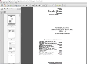
John Deere 700J Crawler Dozer Repair MANUAL TM10269 – PDF DOWNLOAD
(Serial No. 139436-
Description
John Deere 700J Crawler Dozer Repair MANUAL TM10269 – PDF DOWNLOAD
FILE DETAILS:
John Deere 700J Crawler Dozer Repair MANUAL TM10269 – PDF DOWNLOAD
Language : English
Pages :
Downloadable : Yes
File Type : PDF
IMAGES PREVIEW OF THE MANUAL:
DESCRIPTION:
John Deere 700J Crawler Dozer Repair MANUAL TM10269 – PDF DOWNLOAD
(Serial No. 139436-
Foreword
- This manual is written for an experienced technician. Essential tools required in performing certain service work are identified in this manual and are recommended for use. Live with safety: Read the safety messages in the introduction of this manual and the cautions presented throughout the text of the manual.
- This is the safety-alert symbol. When you see this symbol on the machine or in this manual, be alert to the potential for personal injury. Technical manuals are divided in two parts: repair and operation and tests. Repair sections tell how to repair the components.
- Operation and tests sections help you identify the majority of routine failures quickly. Information is organized in groups for the various components requiring service instruction. At the beginning of each group are summary listings of all applicable essential tools, service equipment and tools, other materials needed to do the job, service parts kits, specifications, wear tolerances, and torque values. Technical Manuals are concise guides for specific machines.
- They are on-the-job guides containing only the vital information needed for diagnosis, analysis, testing, and repair. Fundamental service information is available from other sources covering basic theory of operation, fundamentals of troubleshooting, general maintenance, and basic type of failures and their causes.
TABLE OF CONTENTS:
John Deere 700J Crawler Dozer Repair MANUAL TM10269 – PDF DOWNLOAD
Contents 5
General Information 9
Safety 11
Recognize Safety Information 11
Follow Safety Instructions 11
Operate Only If Qualified 12
Wear Protective Equipment 12
Avoid Unauthorized Machine Modifications 12
Inspect Machine 13
Stay Clear of Moving Parts 13
Avoid High-Pressure Fluids 13
Avoid High-Pressure Oil 14
Beware of Exhaust Fumes 14
Prevent Fires 15
Prevent Battery Explosions 15
Handle Chemical Products Safely 16
Dispose of Waste Properly 16
Prepare for Emergencies 16
Add Cab Guarding For Special Uses 17
Start Only From Operator’s Seat 17
Prevent Unintended Machine Movement 17
Avoid Work Site Hazards 18
Keep Riders Off Machine 18
Avoid Backover Accidents 19
Avoid Machine Tip Over 19
Park And Prepare For Service Safely 20
Service Cooling System Safely 20
Remove Paint Before Welding or Heating 21
Make Welding Repairs Safely 22
Drive Metal Pins Safely 22
Torque Values 23
Torque Value 23
Metric Bolt and Cap Screw 23
Additional Metric Cap Screw Torque Values 24
Torque Value 26
Unified Inch Bolt and Cap Screw 26
Service Recommendations for 37° Flare and 30° Cone Seat Connectors 27
Service Recommendations for O-Ring Boss Fittings 28
Service Recommendation 30
O-Ring Boss Fittings In Aluminum Housing—Excavators 30
Service Recommendations For Flared Connections—Straight or Tapered Threads 32
Service Recommendations For Flat Face O-Ring Seal Fittings 33
Service Recommendation 34
O-Ring Face Seal Fittings with SAE Inch Hex Nut and Stud End for High Pressure 34
O-Ring Face Seal Fittings with Metric Hex Nut and Stud End for Standard Pressure 36
O-Ring Face Seal Fittings with Metric Hex Nut and Stud End for High Pressure 38
Service Recommendations for Metric Series Four Bolt Flange Fitting 40
Service Recommendations For Inch Series Four Bolt Flange Fittings 41
Service Recommendation 42
Inch Series Four Bolt Flange For High Pressure 42
Service Recommendations For Non-Restricted Banjo (Adjustable) Fittings 43
Service Recommendations For O-Ring Boss Fittings With Shoulder 45
Service Recommendation 48
Metric 24° O-Ring Seal DIN 20078 48
Tracks 51
Track System 53
Welding Procedure 53
Rock Guards 54
Remove and Install 54
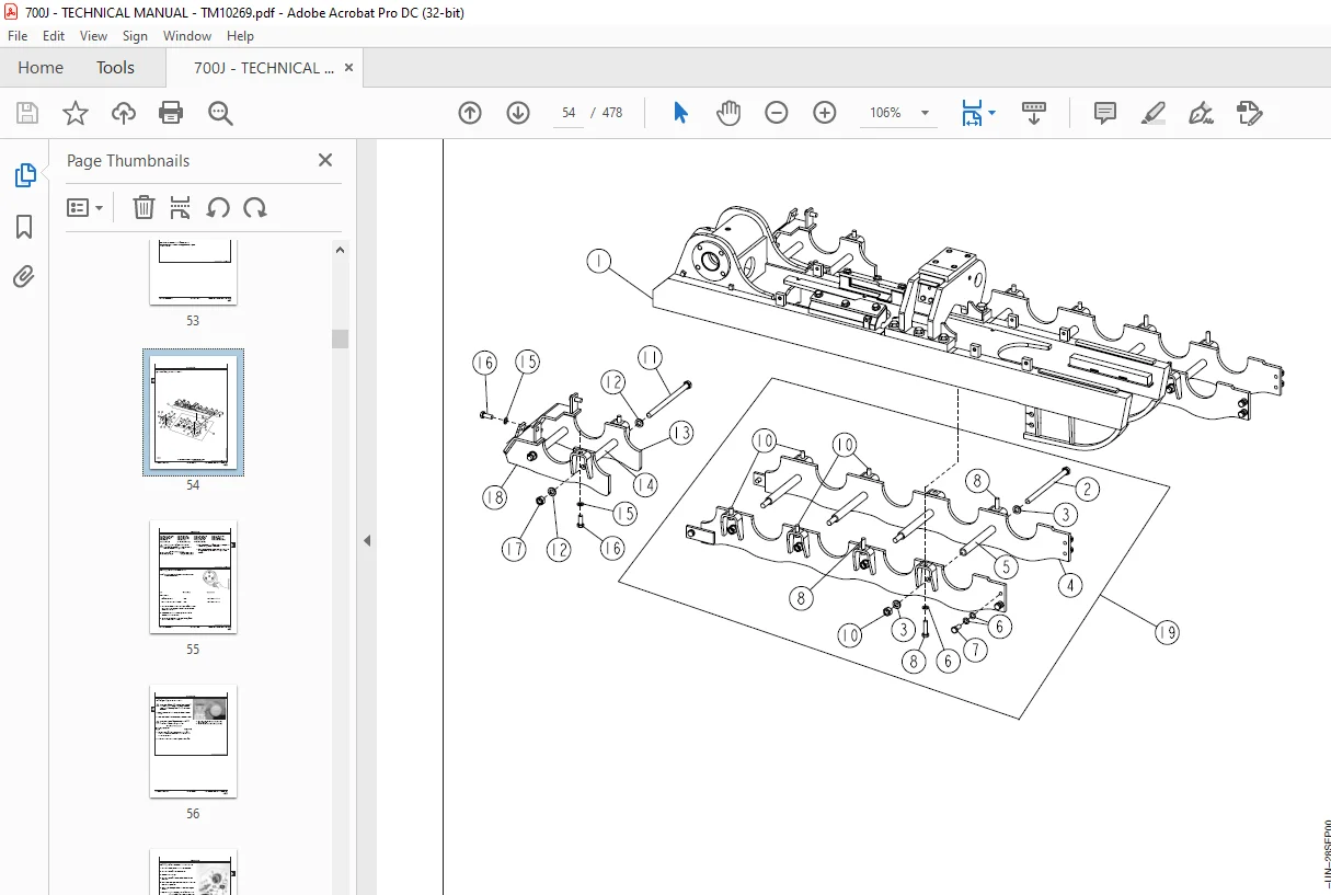
Carrier Roller 55
Measure Wear 55
Remove and Install 56
Disassemble and Assemble 57
Front Idler 60
Inspect Metal Face Seals 60
Carrier Roller 61
Oil Leakage Test 61
Track Roller 62
Measure Wear 62
Remove and Install 63
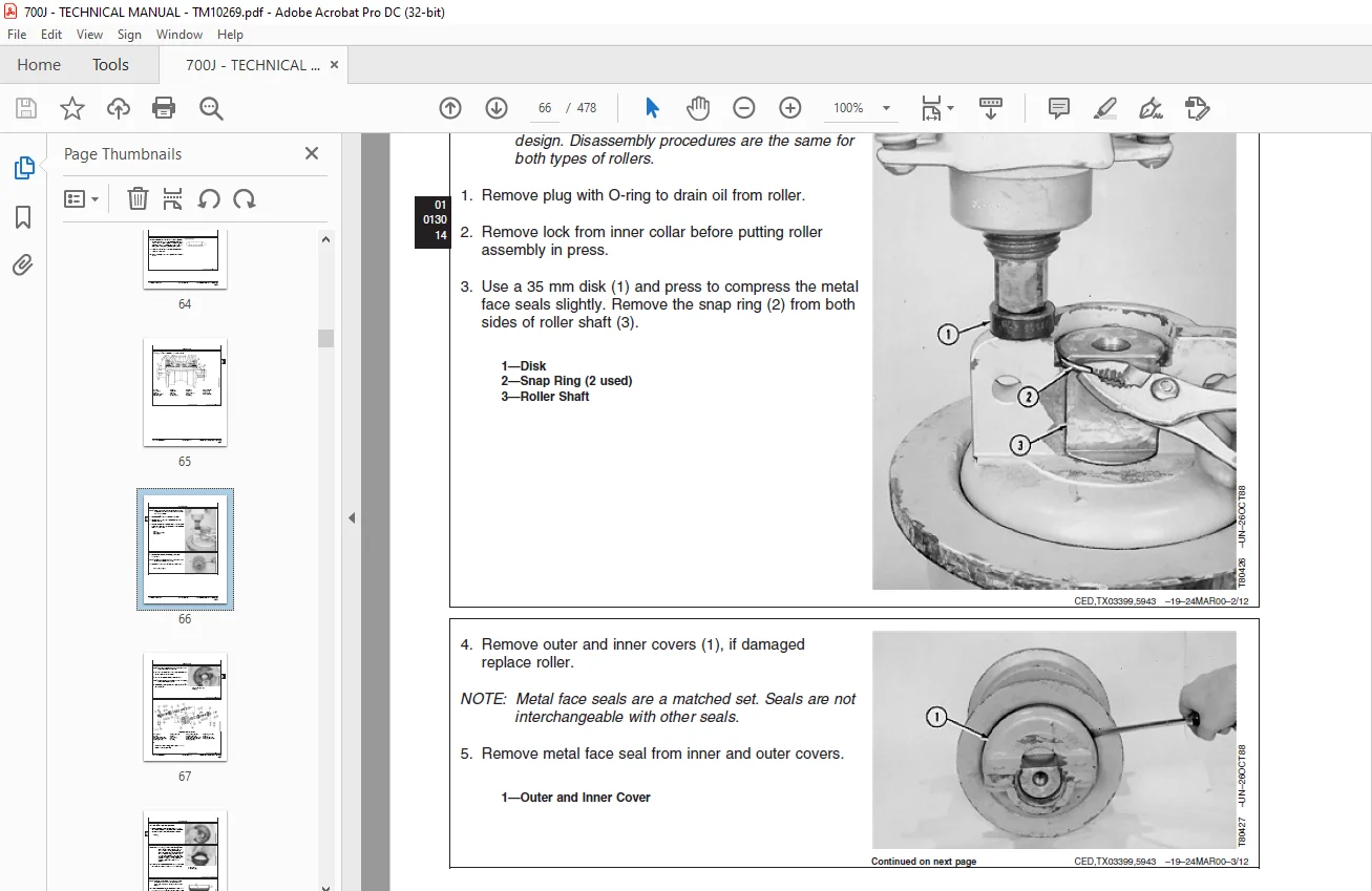
Disassemble and Assemble 65
Leakage Test 71
Track Shoe 72
Measure Grouser Wear 72
Remove and Install 73
Lubricated Track Chain 75
Measure Llink Height 75
Measure Bushing Outside Diameter 75
Measure Track Pitch 76
Remove and Install 76
Disassemble to Turn Bushings and Lubricate Chain 79
Assemble to Turn Bushings and Lubricate Chain 82
Disassemble and Assemble to Turn Pins and Bushings and Not Lubricate 89
Track Sag Adjustment 96
Front Idler 97
Measure Wear 97
Remove and Install 98
Disassemble, Inspect, and Assemble100
Adjustment Procedure101
Test for Oil Leakage103
Track Tension Adjuster104
Remove and Install104
Track Idler Recoil Spring105
Remove and Install105
Disassemble and Assemble106
Track Frame109
Remove and Install109
Remove and Install Wear Strips111
Sprocket Segment112
Remove and Install112
Sprocket113
Remove and Install113
Axles and Suspension Systems115
Drive Axle Housing and Support117
Final Drive117
Remove and Install117
Axle Shaft, Bearings, and Reduction Gear121
Final Drive121
Disassemble and Assemble121
Transmission133
Removal and Installation135
Hydrostatic Pump Remove and Install135
Hydrostatic Motor Remove and Install147
Controls Linkage151
Transmission Control Lever (TCL) Remove and Install151
Transmission Control Lever (TCL) Disassemble and Assemble152
Hydrostatic System171
Hydrostatic Pump Disassemble171
Charge Pump Disassemble and Assemble181
Pump Displacement Control Valve (PDCV) Disassemble and Assemble186
Multi-Function Valve Disassemble and Assemble189
Neutral Charge Relief Valve Disassemble and Assemble191
Hydrostatic Pump Assemble191
Hydrostatic Motor Disassemble200
Hydrostatic Motor Assemble205
Oil Cooler Thermal Bypass Valve Remove and Install218
Hydrostatic Filter Remove and Install219
Hydrostatic Filter Disassemble and Assemble220
Hydrostatic Reservoir Remove and Install222
Engine225
Removal and Installation227
Engine Remove and Install227
Oil Pan235
Remove and Install235
Bleed Fuel System236
Engine Auxiliary Systems237
Cold Weather Starting Aids239
Engine Coolant Heater239
Remove and Install239
Starting Aid241
Remove and Install241
Starting Aid Solenoid242
Remove and Install242
Radiator and Fan Shroud243
Fan Blade and Shroud243
Remove and Install243
Radiator and Oil Cooler245
Remove245
Sand Shield Remove and Install247
Intake System250
Air Cleaner with Turbocharger250
Remove and Install250
External Exhaust System253
Muffler253
Remove and Install253
Mounting Frame255
Engine and Power Train Remove and Install255
External Fuel Supply System257
Fuel Tank257
Remove and Install257
Dampener Drive261
Elements263
Dampener Drive263
Remove and Install263
Park Brake265
Removal and Installation267
Park Brake Valve Remove and Install267
Park Brake Remove and Install268
Control Linkage271
Park Lock Linkage Remove and Install271
Park Lock Linkage Disassemble and Assemble272
Hydraulic System277
Park Brake Valve Disassemble and Assemble277
Park Brake Disassemble and Assemble279
Equipment Attaching283
Drawbar285
Drawbar285
Remove and Install285
Ripper288
Ripper Remove and Install288
Frames, Chassis, or Supporting Structure291
Frame Installation293
Welding Repair of Major Structure293
RIVNUT® (KREMNUT) Fasteners Remove and Install294
Frame and Bottom Covers Remove and Install296
Pivot Shafts Remove and Install297
Crossbar and Lube Lines Remove and Install299
Crossbar Disassemble and Assemble300
Chassis Weights301
Counterweight Remove and Install301
Operator’s Station303
Removal and Installation305
Cab or ROPS Remove and Install305
Operator’s Enclosure313
Slide Glass Remove and Install313
Stationary Glass Remove and Install315
Windowpanes Remove and Install 317
Front Window Wiper Remove and Install320
Door Window Wipers Remove and Install322
Rear Window Wiper Remove and Install324
Window Washer Pumps Remove and Install325
Seat and Seat Belt327
Standard Seat Remove and Install327
Deluxe Seat Remove and Install332
Air Suspension Seat Remove and Install343
Heating and Air Conditioning347
R134a Refrigerant Cautions347
R134a Compressor Oil Charge Check347
R134a Compressor Oil Removal348
R134a Component Oil Charge349
Leakage Testing350
R134a Refrigerant Recovery, Recycling and Charging Station Installation Procedure351
Recover R134a System352
Evacuate R134a System353
Charge R134a System355
Air Conditioner System Cleaning Procedures356
Purge R134a System357
Flush R134a System358
Evaporator or Heater Core Remove and Install360
Expansion Valve Remove and Install363
A/C Freeze Switch Remove and Install364
Upper Cab Heater Blower Motor and Heater Blower Resistor Remove and Install364
Cab Upper Heater Disassemble and Assemble366
Cab or ROPS Under Seat Heater Disassemble and Assemble368
Receiver-Dryer Remove and Install370
Condenser Remove and Install371
Compressor Remove and Install372
Compressor Clutch Disassemble and Assemble374
Clutch Hub Clearance Check376
Compressor Manifold Inspect377
Compressor Disassemble and Assemble378
Sheet Metal and Styling381
Hood and Engine Enclosure383
Hood Remove and Install383
Hood Support and Engine Side Shields Remove and Install384
Grille and Grille Housing386
Grille and Grille Housing Remove and Install386
Main Hydraulic System391
Hydraulic System393
Hydraulic Pump393
Remove and Install393
Hydraulic Pump (With Winch Option) Disassemble and Assemble396
Hydraulic Pump Disassemble and Assemble400
Hydraulic Reservoir402
Remove and Install402
Hydraulic and Hydrostatic Reservoir Cleanout Cover Remove and Install405
Hydraulic Reservoir Disassemble and Assemble410
Hydraulic Filter411
Remove and Install411
Disassemble and Assemble412
Bulldozer413
Blades416
Dozer Blade416
Remove and Install416
Control Linkage420
Hydraulic Control Lever Linkage Remove and Install420
Auxiliary Hydraulic Control Lever Linkage Remove and Install422
Frames423
Dozer C–Frame423
Remove and Install423
Hydraulic System429
Hydraulic Control Valve Remove and Install429
Hydraulic Control Valve431
Disassemble and Assemble431
Hydraulic Control Valve Disassemble and Assemble—IGC434
Hydraulic Control Valve435
Wiper Seals and Seals, Replace435
Disassemble and Assemble Auxiliary Section440
Disassemble and Assemble Angle Section442
Disassemble and Assemble Tilt Section444
Disassemble and Assemble Lift Section446
Integrated Grade Control (IGC) Lever Remove and Install (SN 130886—)448
Integrated Grade Control (IGC) Lever Disassemble and Assemble (SN 130886—)452
Hydraulic Control Valve453
Disassemble and Assemble System Relief Valve453
Disassemble and Assemble System Relief Valve454
Angle, Lift, and Tilt Cylinders Disassemble and Assemble (John Deere 120 Series Cylinders)454
Dealer Fabricated Tools455
Dealer Fabricated Tools457
DFT1041 Track Nut Removal Tool457
DF1063 Final Drive and Pump Lifting Bracket458
DF1065 Final Drive and Pump Adapter Bracket459
DFT1211 Final Drive Lifting Bracket Adapter460
DFT1087 Track Recoil Spring Disassembly and Assembly Guard Tool461
DFT1137 Hydrostatic Motor Removal and Installation Tool462
ST4920 Track Recoil Spring Disassembly and Assembly Tool463
DFT1119 Pump Support467
DFT1130 Adapter468
DFT1132 Hydrostatic Motor and Hydraulic Pump Removal and Installation Tool469
DFT1203 Torque Adapter For Pivot Shaft470
DFT1212 Park Brake Spring Compressor471
DFRW20 Compressor Holding Fixture472
Page Numbers 5
Section 00 9
Group 01 11
S.M 4/1/25