John Deere 750C 850C Crawler Dozer Repair Technical Manual – PDF DOWNLOAD
Original price was: $89.95.$28.95Current price is: $28.95.
John Deere 750C 850C Crawler Dozer Repair Technical Manual – PDF DOWNLOAD
Description
John Deere 750C 850C Crawler Dozer Repair Technical Manual – PDF DOWNLOAD
DESCRIPTION:
John Deere 750C 850C Crawler Dozer Repair Technical Manual – PDF DOWNLOAD
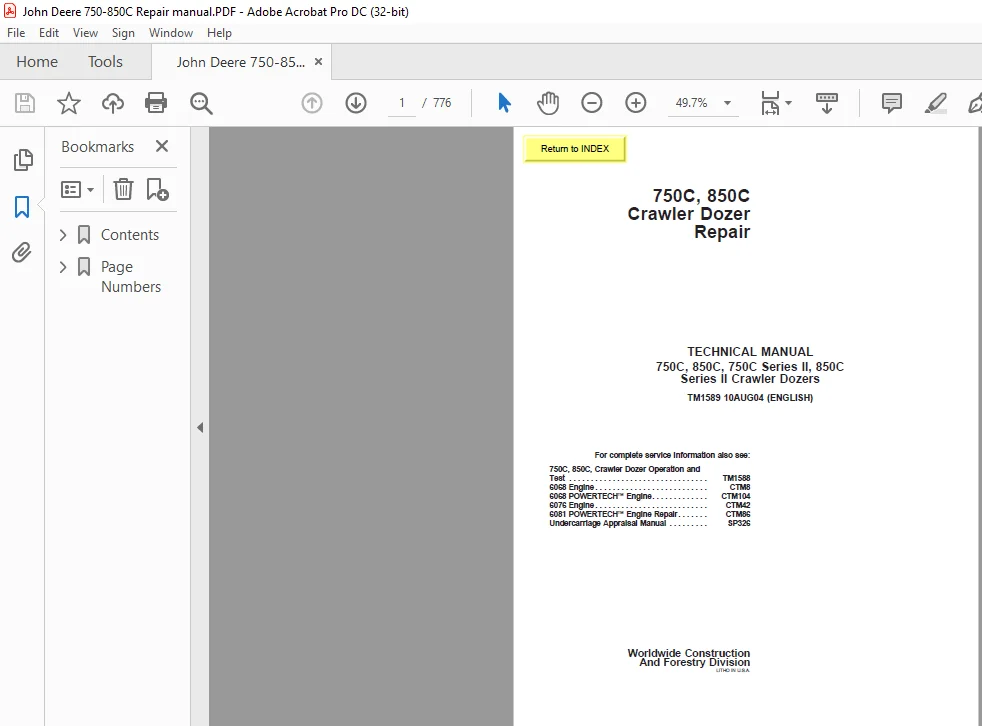
For complete service information also see:
750C, 850C, Crawler Dozer Operation and
Test . . . . . . . . . . . . . . . . . . . . . . . . . . . . . . . . TM1588
6068 Engine . . . . . . . . . . . . . . . . . . . . . . . . . . CTM8
6068 POWERTECHä Engine. . . . . . . . . . . . . CTM104
6076 Engine . . . . . . . . . . . . . . . . . . . . . . . . . . CTM42
6081 POWERTECHä Engine Repair. . . . . . . CTM86
Undercarriage Appraisal Manual . . . . . . . . . SP326
Foreword :
This manual is written for an experienced technician. Essential tools required in performing certain service work are identified in this manual and are recommended for use. Live with safety: Read the safety messages in the introduction of this manual and the cautions presented throughout the text of the manual.
- This is the safety-alert symbol. When you see this symbol on the machine or in this manual, be alert to the potential for personal injury. Technical manuals are divided in two parts: repair and operation and tests. Repair sections tell how to repair the components. Operation and tests sections help you identify the majority of routine problems quickly.
- Information is organized in groups for the various components requiring service instruction. At the beginning of each group are summary listings of all applicable essential tools, service equipment and tools, other materials needed to do the job, service parts kits, specifications, wear tolerances, and torque values.
- Technical Manuals are concise guides for specific machines. They are on-the-job guides containing only the vital information needed for diagnosis, analysis, testing, and repair. Fundamental service information is available from other sources covering basic theory of operation, fundamentals of troubleshooting, general maintenance, and basic type of problems and their causes.
TABLE OF CONTENTS:
John Deere 750C 850C Crawler Dozer Repair Technical Manual – PDF DOWNLOAD
Contents…………………………………………………………………………………………….. 5
General Information……………………………………………………………………………….. 9
Safety……………………………………………………………………………………….. 11
Handle Fluids Safely—Avoid Fires…………………………………………………………….. 11
Prevent Battery Explosions………………………………………………………………….. 11
Prepare for Emergencies…………………………………………………………………….. 11
Prevent Acid Burns…………………………………………………………………………. 12
Handle Chemical Products Safely……………………………………………………………… 13
Avoid High-Pressure Fluids………………………………………………………………….. 13
Park Machine Safely………………………………………………………………………… 14
Support Machine Properly……………………………………………………………………. 14
Wear Protective Clothing……………………………………………………………………. 14
Work In Clean Area…………………………………………………………………………. 15
Service Machines Safely…………………………………………………………………….. 15
Work In Ventilated Area…………………………………………………………………….. 15
Illuminate Work Area Safely…………………………………………………………………. 15
Replace Safety Signs……………………………………………………………………….. 16
Use Proper Lifting Equipment………………………………………………………………… 16
Remove Paint Before Welding or Heating……………………………………………………….. 16
Avoid Heating Near Pressurized Fluid Lines……………………………………………………. 17
Keep ROPS Installed Properly………………………………………………………………… 17
Practice Safe Maintenance…………………………………………………………………… 18
Dispose of Waste Properly…………………………………………………………………… 18
Live With Safety…………………………………………………………………………… 19
General Specifications…………………………………………………………………………. 21
750C Series II Specifications……………………………………………………………….. 21
750C Series II Capacity Specifications……………………………………………………….. 23
750C Series II General Specifications………………………………………………………… 24
750C LT Series II Dimensions………………………………………………………………… 26
750C WT Series II Dimensions………………………………………………………………… 29
750C LGP Series II Dimensions……………………………………………………………….. 31
850C Series II Specifications……………………………………………………………….. 33
850C Series II Capacity Specifications……………………………………………………….. 36
850C Series II General Specifications………………………………………………………… 37
850C LT Series II Dimensions………………………………………………………………… 39
850C WT Series II Dimensions………………………………………………………………… 42
850C LGP Series II Dimensions……………………………………………………………….. 44
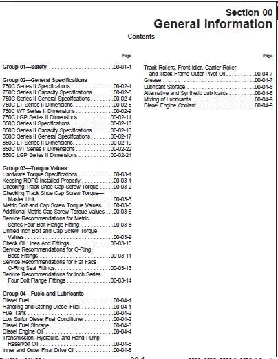
Torque Values…………………………………………………………………………………. 47
Hardware Torque Specifications………………………………………………………………. 47
Keeping ROPS Installed Properly……………………………………………………………… 47
Checking Track Shoe Cap Screw Torque…………………………………………………………. 48
Checking Track Shoe Cap Screw Torque—Master Link………………………………………………. 49
Metric Bolt and Cap Screw Torque Values………………………………………………………. 51
Additional Metric Cap Screw Torque Values…………………………………………………….. 52
Service Recommendations for Metric Series Four Bolt Flange Fitting………………………………. 54
Unified Inch Bolt and Cap Screw Torque Values…………………………………………………. 55
Check Oil Lines And Fittings………………………………………………………………… 56
Service Recommendations for O-Ring Boss Fittings………………………………………………. 57
Service Recommendations for Flat Face O-Ring Seal Fittings……………………………………… 59
Service Recommendations for Inch Series Four Bolt Flange Fittings……………………………….. 60
Fuels and Lubricants…………………………………………………………………………… 63
Diesel Fuel……………………………………………………………………………….. 63
Handling and Storing Diesel Fuel…………………………………………………………….. 63
Fuel Tank…………………………………………………………………………………. 64
Low Sulfur Diesel Fuel Conditioner…………………………………………………………… 64
Diesel Fuel Storage………………………………………………………………………… 65
Diesel Engine Oil………………………………………………………………………….. 66
Transmission, Hydraulic, and Hand Pump Reservoir Oil…………………………………………… 67
Inner and Outer Final Drive Oil……………………………………………………………… 68
Track Rollers, Front Idler, Carrier Roller and Track Frame Outer Pivot Oil……………………….. 69
Grease……………………………………………………………………………………. 69
Lubricant Storage………………………………………………………………………….. 70
Alternative and Synthetic Lubricants…………………………………………………………. 70
Mixing of Lubricants……………………………………………………………………….. 71
Diesel Engine Coolant………………………………………………………………………. 71
Tracks…………………………………………………………………………………………… 73
Track System………………………………………………………………………………….. 75
Essential Tools……………………………………………………………………………. 75
Service Equipment and Tools…………………………………………………………………. 76
Other Material…………………………………………………………………………….. 78
Specifications…………………………………………………………………………….. 79
Remove and Install Rock Guards and Track Guides……………………………………………….. 85
Measure Carrier Roller Wear…………………………………………………………………. 86
Remove and Install Carrier Roller……………………………………………………………. 87
Disassemble and Assemble Carrier Roller………………………………………………………. 88
Inspect Metal Face Seals……………………………………………………………………. 90
Test Carrier Roller for Oil Leakage………………………………………………………….. 92
Measure Track Roller Wear…………………………………………………………………… 93
Remove and Install Track Roller……………………………………………………………… 94
Disassemble Track Roller……………………………………………………………………. 96
Assemble Track Roller………………………………………………………………………. 99
Test Track Roller for Leakage………………………………………………………………..104
Measure Track Shoe Grouser Wear………………………………………………………………105
Remove and Install Track Shoe………………………………………………………………..106
Exploded View of Front Crossbar and Support—750C……………………………………………….108
Remove and Install Front Crossbar and Support—750C……………………………………………..109
Remove and Install Front Crossbar and Support—850C (S.N. —833331)………………………………..111
Check and Adjust Front Crossbar-to-Crossbar Support and Main Frame Clearances (S.N. —833331)………..113
Remove and Install Support Wear Plates (S.N. —833331)…………………………………………..115
Remove and Install Pinned Crossbar and Support—850C (S.N. 833332—907600)………………………….116
Crossbar Lube………………………………………………………………………………119
Remove and Install………………………………………………………………………119
Crossbar…………………………………………………………………………………..120
Disassemble and Assemble…………………………………………………………………120
Measure Link Height…………………………………………………………………………121
Measure Bushing Outside Diameter for Lubricated Track Chain……………………………………..122
Measure Track Pitch for Lubricated Track Chain…………………………………………………124
Remove and Install Lubricated Track Chain……………………………………………………..125
Disassemble Lubricated Track Chain to Turn Bushings and Lubricate Chain…………………………..129
Assemble Lubricated Track Chain to Turn Bushings and Lubricate Chain……………………………..132
Disassemble and Assemble Lubricated Track Chain to Turn Pins and Bushings and Not Lubricate…………139
Adjust Track Sag……………………………………………………………………………146
Track Adjuster Exploded View…………………………………………………………………148
Remove Track Adjuster and Recoil Spring……………………………………………………….149
Install Track Adjuster and Recoil Spring………………………………………………………151
Disassemble and Assemble Recoil Spring………………………………………………………..154
Disassemble and Assemble Track Adjuster Cylinder……………………………………………….157
Remove Track Frame………………………………………………………………………….159
Welding Procedure…………………………………………………………………………..161
Remove and Install A-Frame Bearing and A-Frame Bushings…………………………………………162
Install Track Frame…………………………………………………………………………164
Remove and Install Wear Strip on Inner Guide…………………………………………………..169
Remove and Install Track Frame Upper Wear Strips……………………………………………….170
Remove and Install Track Frame Lower Wear Strips……………………………………………….172
Remove and Install Track Frame Wear Strip Bar………………………………………………….173
Measure Front Idler Wear…………………………………………………………………….174
Remove Front Idler………………………………………………………………………….175
Disassemble Front Idler……………………………………………………………………..176
Inspect Metal Face Seals…………………………………………………………………….178
Exploded View of Front Idler…………………………………………………………………179
Assemble Front Idler………………………………………………………………………..180
Install Front Idler…………………………………………………………………………187
Adjust Front Idler Vertical Movement………………………………………………………….188
Adjust Front Idler Horizontal Movement………………………………………………………..189
Test Front Idler for Oil Leakage……………………………………………………………..190
Remove and Install Sprocket Segment…………………………………………………………..191
Dealer Fabricated Tools…………………………………………………………………………193
DFT1087 Track Recoil Spring Compression Tool Guard……………………………………………..193
DFT1041 Track Nut Removal Tool……………………………………………………………….194
ST4920 Track Recoil Spring Compression Tool……………………………………………………195
Axles and Suspension Systems………………………………………………………………………..199
Drive Axle Housing and Support…………………………………………………………………..201
Service Equipment and Tools………………………………………………………………….201
Other Material……………………………………………………………………………..201
Specifications……………………………………………………………………………..202
Remove and Install Final Drive Axle Housing And Support…………………………………………203
Axle Shaft, Bearings and Reduction Gears………………………………………………………….209
Service Equipment and Tools………………………………………………………………….209
Other Material……………………………………………………………………………..209
Specifications……………………………………………………………………………..210
Planet Carrier Housing Assembly Cross Section………………………………………………….212
Remove and Install Planet Housing…………………………………………………………….213
Disassemble and Assemble Planet Carrier Housing………………………………………………..216
Remove Ring Gear, Hub and Sprocket Frame………………………………………………………218
Disassemble and Assemble Ring Gear Hub and Sprocket Frame……………………………………….220
Inspect Metal Face Seals…………………………………………………………………….221
Install Gear, Hub and Sprocket Frame………………………………………………………….222
Remove and Install Final Drive Housing Assembly………………………………………………..225
Disassemble and Assemble Final Drive Housing Cover Assembly……………………………………..228
Dealer Fabricated Tools…………………………………………………………………………233
Dealer Fabricated Tools……………………………………………………………………..233
DFT1079 Final Drive Lifting Fixture Adapter……………………………………………………234
DFT1078 Final Drive Lifting Fixture…………………………………………………………..236
Transmission………………………………………………………………………………………239
Remove and Install……………………………………………………………………………..241
Essential Tools…………………………………………………………………………….241
Service Equipment and Tools………………………………………………………………….242
Other Material……………………………………………………………………………..242
Specifications……………………………………………………………………………..243
Remove and Install Hydrostatic Pumps………………………………………………………….244
Remove and Install Hydrostatic Motors…………………………………………………………251
Hydrostatic Motor Speed Sensor Adjustment……………………………………………………..254
Hydrostatic Pump and Motor Initial Start-Up Procedure…………………………………………..255
Control Linkage………………………………………………………………………………..259
Essential Tools…………………………………………………………………………….259
Service Equipment and Tools………………………………………………………………….259
Other Material……………………………………………………………………………..260
Specifications……………………………………………………………………………..261
Remove and Install Steering Pedal…………………………………………………………….264
Disassemble and Assemble FNR Control Assembly—Pedal Steer (S.N. —XXXXXX)………………………….266
FNR Control Assembly Component Location—Pedal Steer (S.N. —XXXXXX)……………………………….268
FNR and Neutral Start Switch Adjustment—Pedal Steer (S.N. —XXXXXX)……………………………….269
Disassemble and Assemble FNR Control Assembly—Single Lever Steer (S.N. —XXXXXX)……………………272
FNR Control Assembly Component Location—Single Lever Steer (S.N. —XXXXXX)…………………………274
FNR and Neutral Start Switch Adjustment—Single Lever Steer (S.N. —XXXXXX)…………………………275
Single Lever Control………………………………………………………………………..280
Exploded View…………………………………………………………………………..280
Remove and Install………………………………………………………………………282
Disassemble and Assemble Single Lever Control Linkage (SLC) With Speed In Grip (S.N. XXXXXX— )………283
Rotary Sensor Component Location With (SIG) Speed In Grip (S.N. XXXXXX— )…………………………300
Park Lock Linkage Adjustment…………………………………………………………………302
Hydrostatic System……………………………………………………………………………..305
Essential Tools…………………………………………………………………………….305
Service Equipment and Tools………………………………………………………………….305
Other Material……………………………………………………………………………..306
Specifications……………………………………………………………………………..307
Disassemble Hydrostatic Pump…………………………………………………………………310
Disassemble and Assemble Charge Pump………………………………………………………….319
Disassemble and Assemble Pump Displacement Control Valve (PDCV)………………………………….320
Remove and Install Multi-Function Valve……………………………………………………….321
Remove and Install Charge Pressure Manifold……………………………………………………322
Disassemble and Assemble Multi-Function Valve………………………………………………….323
Assemble Hydrostatic Pump……………………………………………………………………324
Disassemble and Assemble Oil Cooler Bypass Valve……………………………………………….334
Disassemble Hydrostatic Motor………………………………………………………………..334
Assemble Hydrostatic Motor…………………………………………………………………..345
Remove and Install Hydrostatic Oil Filter……………………………………………………..354
Dealer Fabricated Tools…………………………………………………………………………355
DFT1063 Pump Lifting Bracket…………………………………………………………………355
DFT1130 Adapter…………………………………………………………………………….356
DFT1132 Hydrostatic Motor Removal and Installation Tool…………………………………………357
DFT1137 Hydrostatic Motor Removal and Installation Tool…………………………………………358
DFT1164 Speed Sensor Adjusting Tool…………………………………………………………..359
Engine……………………………………………………………………………………………361
Removal and Installation………………………………………………………………………..363
6068 John Deere Engine—Use CTM8………………………………………………………………363
6068 John Deere POWERTECH™ Engine—Use CTM104…………………………………………………..363
6076 John Deere Engine—Use CTM42……………………………………………………………..363
6081 John Deere POWERTECH™ Engine Repair—Use CTM86……………………………………………..363
Essential Tools…………………………………………………………………………….364
Other Material……………………………………………………………………………..366
Specifications……………………………………………………………………………..367
Remove and Install Engine……………………………………………………………………368
Remove and Install Oil Pan…………………………………………………………………..377
Remove and Install Fuel Filter Check Valve—850C………………………………………………..378
Remove DB4 Fuel Injection Pump—750C…………………………………………………………..379
Installing DB4 Fuel Injection Pump—750C……………………………………………………….381
Remove In-Line Fuel Injection Pump—850C……………………………………………………….384
Install In-Line Fuel Injection Pump—850C………………………………………………………385
JT07158 TIME TRAC® Installation………………………………………………………………390
Injection Pump Dynamic Timing—750C……………………………………………………………391
Fuel Shut-Off Solenoid Adjustment—850C (S.N. —822867)…………………………………………..393
Disassemble and Assemble Final Fuel Filter—750C………………………………………………..394
Disassemble and Assemble Primary Fuel Filter (Water Separator)…………………………………..395
Bleed the Fuel System—750C…………………………………………………………………..396
Bleed the Fuel System—850C…………………………………………………………………..397
Primary Fuel Filter, Drain Valve—750C…………………………………………………………398
Primary Fuel Filter, Drain Valve—850C…………………………………………………………398
Remove and Install Engine Mounts……………………………………………………………..400
Engine Auxiliary Systems……………………………………………………………………………403
Cold Weather Starting Aid……………………………………………………………………….405
Specifications……………………………………………………………………………..405
Remove and Install Engine Coolant Heater………………………………………………………406
Cooling System…………………………………………………………………………………409
6068 John Deere Engine—Use CTM8………………………………………………………………409
6068 John Deere POWERTECH™ Engine—Use CTM104…………………………………………………..409
6076 John Deere Engine—Use CTM42……………………………………………………………..409
6081 John Deere POWERTECH™ Engine Repair—Use CTM86……………………………………………..409
Essential Tools…………………………………………………………………………….410
Service Equipment and Tools………………………………………………………………….410
Specifications……………………………………………………………………………..411
Remove and Install Guards, Shroud and Fan……………………………………………………..412
Remove and Install Fan Belt and Adjuster—750C (S.N.—831315)……………………………………..413
Remove, Install, Inspect Serpentine Fan Belt—850C and 750C (S.N. 831316— )………………………..415
Remove and Install Radiator and Oil Cooler…………………………………………………….416
Remove and Install Hydraulic Oil Cooler……………………………………………………….420
Speed Controls…………………………………………………………………………………425
Essential Tools…………………………………………………………………………….425
Service Equipment and Tools………………………………………………………………….425
Other Material……………………………………………………………………………..426
Specifications……………………………………………………………………………..427
JT05801 Clamp-On Digital Tachometer Installation……………………………………………….429
Remove and Install Engine Speed Control……………………………………………………….430
Remove and Install Engine Speed Control Linkage and Shaft 750C and 850C (S.N. —822867)……………..432
Remove and Install Engine Speed Control Linkage and Shaft 850C (S.N. 822868—)……………………..434
Engine Speed Control Linkage Rod—850C (S.N. —822867)……………………………………………436
Engine Speed Control Linkage Rod—750C…………………………………………………………437
Remove and Install Decelerator……………………………………………………………….438
Engine Speed Adjustment—750C…………………………………………………………………440
Engine Speed Adjustment—850C…………………………………………………………………443
Engine Speed Control Cable Adjustment…………………………………………………………447
Engine Speed Control Sensor Adjustment (750C, 850C S.N.—875378)………………………………….449
Decelerator Sensor Adjustment—Single Lever Steer……………………………………………….451
Throttle Sensor Adjustment—850C (S.N. 822868— )………………………………………………..453
Intake System………………………………………………………………………………….455
Remove and Install Air Cleaner……………………………………………………………….455
Test Air Intake System for Leaks……………………………………………………………..456
External Exhaust Systems………………………………………………………………………..457
Remove and Install Muffler…………………………………………………………………..457
External Fuel Supply Systems…………………………………………………………………….459
Other Material……………………………………………………………………………..459
Specifications……………………………………………………………………………..459
Remove and Install Fuel Tank…………………………………………………………………460
Remove and Install Fuel Lines—750C……………………………………………………………462
Remove and Install Fuel Lines—850C……………………………………………………………463
Dealer Fabricated Tools…………………………………………………………………………465
DFT1140 Serpentine Belt Removal and Installation Tool (850C)…………………………………….465
Dampener Drive…………………………………………………………………………………….467
Elements………………………………………………………………………………………469
Other Material……………………………………………………………………………..469
Specifications……………………………………………………………………………..469
Remove and Install Dampener Drive…………………………………………………………….470
Park Brake………………………………………………………………………………………..471
Park Brake…………………………………………………………………………………….473
Specifications……………………………………………………………………………..473
Park Brake Cross Section…………………………………………………………………….475
Remove and Install Park Brakes……………………………………………………………….476
Control Linkage………………………………………………………………………………..479
Service Equipment and Tools………………………………………………………………….479
Specifications……………………………………………………………………………..479
Remove and Install Park Brake Pedal…………………………………………………………..480
Remove and Install Park Brake Valve Linkage……………………………………………………481
Remove and Install Park Lock Lever and Brake Cable and Linkage…………………………………..482
Park Lock Linkage Adjustment…………………………………………………………………484
Hydraulic System……………………………………………………………………………….487
Remove and Install Park Brake Valve…………………………………………………………..487
Disassemble and Assemble Park Brake Valve……………………………………………………..488
Equipment Attaching………………………………………………………………………………..489
Drawbar……………………………………………………………………………………….491
Specifications……………………………………………………………………………..491
Remove and Install Extended Rigid Drawbar……………………………………………………..492
Remove and Install Rigid Drawbar……………………………………………………………..494
Electrical System………………………………………………………………………………….495
Batteries, Support, and Cables…………………………………………………………………..497
Service Equipment and Tools………………………………………………………………….497
Specifications……………………………………………………………………………..497
Service Batteries Carefully………………………………………………………………….498
Procedure for Testing Batteries………………………………………………………………500
Checking Electrolyte Specific Gravity…………………………………………………………501
Check Battery Electrolyte Level and Terminals………………………………………………….503
Using Booster Batteries—24 Volt System………………………………………………………..505
Charge Battery……………………………………………………………………………..506
Remove and Install Batteries…………………………………………………………………507
Alternator, Regulator and Charging System Wiring…………………………………………………..509
Alternators and Starting Motors—Use CTM77……………………………………………………..509
Essential Tools…………………………………………………………………………….509
Specifications……………………………………………………………………………..509
Remove and Install Alternator………………………………………………………………..510
Lighting System………………………………………………………………………………..511
Remove and Install Light Switch………………………………………………………………511
Remove and Install Halogen Bulb………………………………………………………………511
Remove and Install Dome Light and Swivel Light…………………………………………………512
Wiring Harness and Switches……………………………………………………………………..513
Essential Tools…………………………………………………………………………….513
Cab/ROPS Harness Component Identification—(750C S.N. —XXXXXX) and (850C S.N. —822867)………………516
Cab/ROPS Harness Component Identification—850C (S.N. 822868—XXXXXX)………………………………520
Cab/ROPS Harness Component Identification—750C, 850C (S.N. XXXXXX— )……………………………..526
Chassis Harness Component Identification………………………………………………………532
Engine/Pump Harness Component Identification—750C (S.N. —831315)…………………………………534
Engine/Pump Harness Component Identification—750C (S.N. 831316— )………………………………..536
Engine/Pump Harness Component Identification—850C (S.N. —822867)…………………………………538
Engine/Pump Harness Component Identification—850C (S.N. 822868—)…………………………………540
Grille Housing Harness Component Identification—750C (S.N. —831315) and 850C (S.N. —822867)…………542
Grille Housing Harness Component Identification—750C (S.N. 831316— ) and 850C (S.N. 822868— )……….544
Motor Harness Electrical Component Identification………………………………………………546
Wiper Harness Electrical Component Identification………………………………………………548
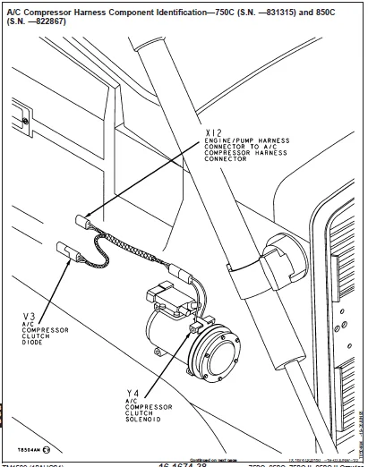
A/C Compressor Harness Component Identification—750C (S.N. —831315) and 850C (S.N. —822867)…………550
A/C Condenser Harness Electrical Component Identification……………………………………….552
Replace DEUTSCH™ Connectors………………………………………………………………….553
Install DEUTSCH™ Contact…………………………………………………………………….555
Replace WEATHER PACK™ Connectors……………………………………………………………..556
Install WEATHER PACK™ Contact………………………………………………………………..557
Replace METRI-PACK™ Connector………………………………………………………………..559
Remove Connector Body from Blade Terminals…………………………………………………….560
System Controls………………………………………………………………………………..561
Welding Procedure…………………………………………………………………………..561
Remove and Install Transmission Controller…………………………………………………….562
Remove and Install Display Monitor……………………………………………………………563
Remove and Install Engine Controller—850C (S.N. 822868— )……………………………………….563
Motors and Actuators……………………………………………………………………………565
John Deere Starting Motor—Use CTM77…………………………………………………………..565
Remove and Install Starting Motor…………………………………………………………….565
Frames, Chassis, or Supporting Structure……………………………………………………………..567
Frame Installation……………………………………………………………………………..569
Specifications……………………………………………………………………………..569
Welding Repair of Major Structures……………………………………………………………569
Remove and Install Sub-Frame Fasteners………………………………………………………..570
Frame Bottom Guards…………………………………………………………………………….571
Other Material……………………………………………………………………………..571
Remove and Install Bottom Guards—750C…………………………………………………………571
Remove and Install Bottom Guards—850C…………………………………………………………572
Chassis Weights………………………………………………………………………………..573
Specifications……………………………………………………………………………..573
Remove and Install Counterweight—850C…………………………………………………………573
Operator’s Station…………………………………………………………………………………575
Removal and Installation………………………………………………………………………..577
Service Equipment and Tools………………………………………………………………….577
Specifications……………………………………………………………………………..577
Remove and Install Cab/ROPS………………………………………………………………….578
Operator Enclosure……………………………………………………………………………..587
Other Material……………………………………………………………………………..587
Specifications……………………………………………………………………………..587
Disassemble and Assemble Cab/ROPS Tilt Cylinder………………………………………………..588
Remove and Install Cab/ROPS Tilt Cylinder……………………………………………………..589
Remove and Install Hand Pump Assembly…………………………………………………………591
Disassemble and Assemble Hand Pump……………………………………………………………592
Remove and Install Cab/ROPS Mounts and Isolators……………………………………………….593
Remove and Install Window……………………………………………………………………595
Remove and Install Windowpanes……………………………………………………………….596
Remove and Install Cab Covers………………………………………………………………..598
Remove and Install Wiper Motor Assemblies……………………………………………………..599
Remove and Install Cab Doors and Hinges……………………………………………………….600
Remove and Install Door Hold Open Latch……………………………………………………….601
Remove and Install Windshield Washer………………………………………………………….602
Seat and Seat Belt……………………………………………………………………………..603
Disassemble and Assemble Seat………………………………………………………………..603
Heating and Air Conditioning…………………………………………………………………….609
Essential Tools…………………………………………………………………………….609
Service Equipment and Tools………………………………………………………………….610
Other Material……………………………………………………………………………..611
Specifications……………………………………………………………………………..612
R134a Refrigerant Theory of Operation…………………………………………………………614
R134a Refrigerant Cautions…………………………………………………………………..615
R134a Compressor Oil Charge Check…………………………………………………………….616
R134a Compressor Oil Removal…………………………………………………………………617
R134a Component Oil Charge…………………………………………………………………..618
R134a Refrigerant Recovery, Recycling and Charging Station Installation Procedure………………….619
Recover R134a System………………………………………………………………………..620
Evacuate R134a System……………………………………………………………………….621
Charge R134a System…………………………………………………………………………623
Check and Adjust Compressor Belt Tension—750C (S.N. —831315)…………………………………….624
Remove and Install Air Conditioning Compressor—750C (S.N. —831315)……………………………….626
Remove and Install Air Conditioning Compressor—750C (S.N. 831316— )………………………………628
Remove and Install Air Conditioning Compressor—850C…………………………………………….629
Disassemble and Inspect Compressor……………………………………………………………630
Assemble Compressor…………………………………………………………………………637
Inspect Compressor Manifolds…………………………………………………………………639
Remove and Install Receiver/Dryer…………………………………………………………….640
Remove and Install Evaporator………………………………………………………………..642
Remove and Install Condenser…………………………………………………………………644
Remove and Install Heater Pressurizer…………………………………………………………646
Sheet Metal……………………………………………………………………………………….649
Hood and Engine Enclosures………………………………………………………………………651
Specifications……………………………………………………………………………..651
Remove and Install Hood……………………………………………………………………..652
Remove and Install Hood Support and Engine Side Shields…………………………………………654
Grille and Grille Housing……………………………………………………………………….657
Specifications……………………………………………………………………………..657
Remove and Install Grille Housing…………………………………………………………….658
Safety, Convenience and Miscellaneous………………………………………………………………..661
Horn and Warning Devices………………………………………………………………………..663
Remove and Install Reverse Alarm……………………………………………………………..663
Adjust Reverse Warning Alarm Volume…………………………………………………………..663
Bulldozer…………………………………………………………………………………………665
Removal and Installation………………………………………………………………………..667
Specifications……………………………………………………………………………..667
Remove and Install Angledozer or Bulldozer Blade and Frame (Outside Dozer)………………………..668
Remove and Install Trunnion (Outside Dozer)……………………………………………………669
Trunnion Shim Adjustment and 850C Pat Trunnion (S.N. —898365)……………………………………670
Trunnion Shim Adjustment 850C (PAT) (S.N. 898366— )…………………………………………….670
Remove and Install (PAT) All Hydraulic Blade with C—Frame 850C…………………………………..671
Blade…………………………………………………………………………………………673
Specifications……………………………………………………………………………..673
Remove and Install Bulldozer (Outside Dozer)…………………………………………………..674
Remove and Install Cutting Edges and End Bits………………………………………………….675
Remove and Install (PAT) Six Way Blade 850C……………………………………………………676
Controls Linkage……………………………………………………………………………….677
Other Material……………………………………………………………………………..677
Specifications……………………………………………………………………………..677
Remove and Install T-Bar Linkage……………………………………………………………..678
Remove and Install Two Function Hydraulic Linkage………………………………………………680
Remove and Install Third Function Hydraulic Linkage…………………………………………….682
Frames………………………………………………………………………………………..685
Specifications……………………………………………………………………………..685
Remove and Install Bulldozer Pushbeam…………………………………………………………685
Remove and Install Pitch Jack………………………………………………………………..687
Remove and Install Struts……………………………………………………………………688
Disassemble and Assemble Pushbeams, Struts and Pitch Jack……………………………………….690
Blade Pitch Adjustment………………………………………………………………………691
Disassemble and Assemble Lift Cylinder Pivot Sub-frame………………………………………….692
Hydraulic System……………………………………………………………………………….693
Special or Essential Tools…………………………………………………………………..693
Service Equipment and Tools………………………………………………………………….693
Other Material……………………………………………………………………………..694
Specifications……………………………………………………………………………..695
Remove and Install Hydraulic Pump…………………………………………………………….698
Disassemble and Assemble Hydraulic Pump……………………………………………………….699
Remove and Install Plug Or Winch PTO Shaft From Hydraulic Pump…………………………………..701
Remove and Install Hydrostatic and Hydraulic Reservoir………………………………………….703
Hydraulic and Hydrostatic Reservoir Cleanout Cover Remove and Install (S.N. 925753— )………………704
Disassemble and Assemble Reservoir……………………………………………………………708
Remove and Install Hydraulic Filter…………………………………………………………..709
Disassemble and Assemble Hydraulic Filter……………………………………………………..710
Remove and Install Dozer Control Valve………………………………………………………..711
Component Location—All Hydraulic Dozer………………………………………………………..712
Component Location—Bulldozer Hydraulics……………………………………………………….713
Component Location—Angle Dozer Hydraulics……………………………………………………..714
Component Location—850C (PAT) Blade (S.N. XXXXXX— )…………………………………………….715
Disassemble and Assemble Dozer Control Valve…………………………………………………..716
Installing Valve Seal Kit in Cap End………………………………………………………….719
Installing Valve Seal Kit in Tang End…………………………………………………………721
Disassemble and Assemble System Relief Valve…………………………………………………..723
Disassemble and Assemble Circuit Relief Valve with Anti-Cavitation……………………………….724
Remove and Install Quick Drop Valve…………………………………………………………..725
Disassemble and Assemble Quick Drop Valve……………………………………………………..727
Remove and Install Tilt Cylinder—Outside Dozer…………………………………………………728
Cross Section of a 180 Series (Tilt) Cylinder—Outside Dozer……………………………………..729
Disassemble Tilt Cylinder—Outside Dozer……………………………………………………….729
Assemble Tilt Cylinder—Outside Dozer………………………………………………………….732
Remove and Install Blade Lift Cylinder—Outside Dozer……………………………………………737
Disassemble and Assemble Blade Lift Cylinder (S.N.—831315 )……………………………………..739
Disassemble and Assemble Blade Lift Cylinder—Outside Dozer (S.N. 831316— )………………………..742
Remove and Install Tilt Cylinder For (PAT) Six-Way Blade 850C (S.N. —XXXXXX)………………………744
Remove and Install Angle Cylinder For (PAT) Six-Way Blade 850C (S.N. —XXXXXX)……………………..746
Disassemble 120 Series Blade Tilt (PAT) (S.N. XXXXXX— ) and Lift Cylinder (PAT) (S.N. XXXXXX— )……..748
Cross Section of 120 Series Blade Lift (PAT) (S.N. XXXXXX—) and Tilt Cylinder (PAT) (S.N. XXXXXX— )….751
Assemble 120 Series Blade Tilt (PAT) (S.N. XXXXXX—) and Lift Cylinder (PAT) (S.N. XXXXXX— )…………752
Disassemble 125 Series Blade Angle Cylinder (PAT) (S.N. XXXXXX— )………………………………..757
Cross Section of 125 Series Blade Angle Cylinder (PAT) (S.N. XXXXXX— )……………………………759
Assemble 125 Series Blade Angle Cylinder (PAT) (S.N. XXXXXX— )…………………………………..760
Dealer Fabricated Tools…………………………………………………………………………767
DFT1180 Cylinder Nut Torque Tool……………………………………………………………..767
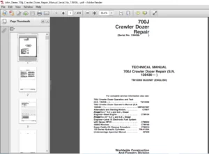
IMAGES PREVIEW OF THE MANUAL:
JOHN DEERE 750C 850C CRAWLER DOZER REPAIR TECHNICAL MANUAL – PDF DOWNLOAD:
PLEASE NOTE:
- This is the SAME MANUAL used by the dealerships to diagnose your vehicle
- No waiting for couriers / posts as this is a PDF manual and you can download it within 2 minutes time once you make the payment.
- Your payment is all safe and the delivery of the manual is INSTANT – You will be taken to the DOWNLOAD PAGE.
- So have no hesitations whatsoever and write to us about any queries you may have : heydownloadss @gmail.com
S.V