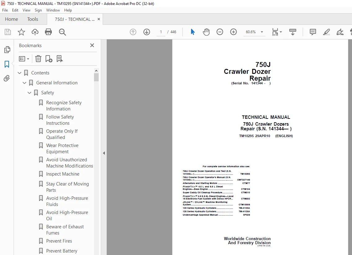
John Deere 750J Crawler Dozer Repair Manual SN 141344 – PDF DOWNLOAD
$28.95
John Deere 750J Crawler Dozer Repair Manual SN 141344 – PDF DOWNLOAD
Description
John Deere 750J Crawler Dozer Repair Manual SN 141344 – PDF DOWNLOAD
FILE DETAILS:
John Deere 750J Crawler Dozer Repair Manual SN 141344 – PDF DOWNLOAD
Language : English
Pages :446
Downloadable : Yes
File Type : PDF
IMAGES PREVIEW OF THE MANUAL:
DESCRIPTION:
John Deere 750J Crawler Dozer Repair Manual SN 141344 – PDF DOWNLOAD
Foreword
- This manual is written for an experienced technician. Essential tools required in performing certain service work are identified in this manual and are recommended for use. Live with safety: Read the safety messages in the introduction of this manual and the cautions presented throughout the text of the manual.
- This is the safetyalert symbol. When you see this symbol on the machine or in this manual, be alert to the potential for personal injury. Technical manuals are divided in two parts: repair and operation and tests. Repair sections tell how to repair the components. Operation and tests sections help you identify the majority of routine failures quickly. Information is organized in groups for the various components requiring service instruction.
- At the beginning of each group are summary listings of all applicable essential tools, service equipment and tools, other materials needed to do the job, service parts kits, specifications, wear tolerances, and torque values. Technical Manuals are concise guides for specific machines.
- They are onthejob guides containing only the vital information needed for diagnosis, analysis, testing, and repair. Fundamental service information is available from other sources covering basic theory of operation, fundamentals of troubleshooting, general maintenance, and basic type of failures and their causes.
TABLE OF CONTENTS:
John Deere 750J Crawler Dozer Repair Manual SN 141344 – PDF DOWNLOAD
Contents 5
General Information 7
Safety 9
Recognize Safety Information 9
Follow Safety Instructions 9
Operate Only If Qualified 9
Wear Protective Equipment 10
Avoid Unauthorized Machine Modifications 10
Inspect Machine 10
Stay Clear of Moving Parts 10
Avoid High-Pressure Fluids 11
Avoid High-Pressure Oil 11
Beware of Exhaust Fumes 12
Prevent Fires 12
Prevent Battery Explosions 12
Handle Chemical Products Safely 13
Dispose of Waste Properly 13
Prepare for Emergencies 13
Add Cab Guarding For Special Uses 14
Use Steps and Handholds Correctly 14
Start Only From Operator’s Seat 14
Use and Maintain Seat Belt 15
Prevent Unintended Machine Movement 15
Avoid Work Site Hazards 16
Keep Riders Off Machine 16
Avoid Backover Accidents 17
Avoid Machine Tip Over and Machine Damage 17
Add and Operate Attachments Safely 17
Park and Prepare for Service Safely 18
Service Cooling System Safely 18
Remove Paint Before Welding or Heating 18
Make Welding Repairs Safely 19
Drive Metal Pins Safely 19
Torque Values 21
Metric Bolt and Cap Screw Torque Values 21
Additional Metric Cap Screw Torque Values 22
Unified Inch Bolt and Cap Screw Torque Values 23
Service Recommendations for 37° Flare and 30° Cone Seat Connecto 24
Service Recommendations for O-Ring Boss Fittings 24
O-Ring Boss Fittings In Aluminum Housing Service Recommendations 26
Service Recommendations For Flared Connections—Straight or Taper 27
Service Recommendations For Flat Face O-Ring Seal Fittings 28
O-Ring Face Seal Fittings With SAE Inch Hex Nut And Stud End For 29
O-Ring Face Seal Fittings With Metric Hex Nut And Stud End For S 31
O-Ring Face Seal Fittings With Metric Hex Nut And Stud End For H 33
Service Recommendations for Metric Series Four Bolt Flange Fitti 35
Service Recommendations For Inch Series Four Bolt Flange Fitting 36
Inch Series Four Bolt Flange Fitting For High Pressure Service R 37
Service Recommendations For Non-Restricted Banjo (Adjustable) Fi 38
Service Recommendations For O-Ring Boss Fittings With Shoulder 39
Metric 24° O-Ring Seal DIN 20078 Service Recommendations 41
Tracks 43
Track System 45
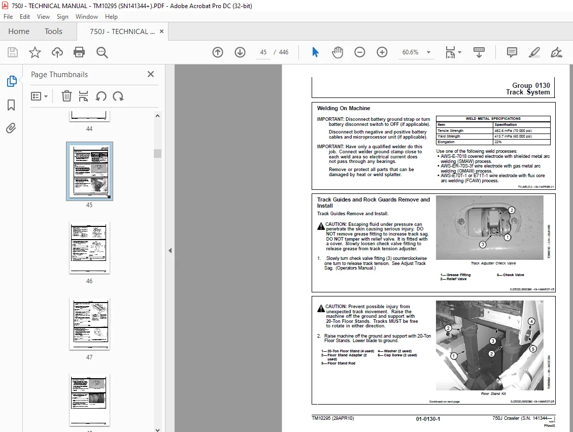
Welding On Machine 45
Track Guides and Rock Guards Remove and Install 45
Carrier Roller Wear Inspection 47
Carrier Roller Remove and Install 48
Carrier Roller Disassemble and Assemble 49
Metal Face Seals Inspection 51
Carrier Roller Leakage Test 53
Track Roller Wear Inspection 53
Track Roller Remove and Install 54
Track Roller Disassemble and Assemble 57
Track Roller Leakage Test 67
Track Shoe Grouser Wear Inspection 68
Track Shoe Remove and Install 69
Pivot Shaft Remove and Install 70
Crossbar Remove and Install 70
Crossbar Disassemble and Assemble 74
Track Link Height Inspection 75
Bushing Outside Diameter for Lubricated Track Chain Inspection 76
Track Pitch for Lubricated Track Chain Inspection 76
Lubricated Track Chain Remove and Install 77
Lubricated Track Chain to Turn Bushings and Lubricate Chain Disa 81
Lubricated Track Chain to Turn Bushings and Lubricate Chain Asse 83
Lubricated Track Chain to Turn Pins and Bushings and Not Lubrica 90
Track Sag Adjustment 95
Track Adjuster Cylinder and Recoil Spring Remove and Install 96
Track Adjuster Recoil Spring Disassemble and Assemble 98
Track Adjuster Cylinder Disassemble and Assemble106
Track Frame Remove and Install107
Front Idler Wear Inspection113
Front Idler Remove and Install113
Front Idler Disassemble and Assemble119
Front Idler Vertical Movement Adjustment126
Front Idler Oil Leakage Test127
Sprocket Segment Remove and Install128
Axles and Suspension Systems129
Drive Axle Housing and Support131
Final Drive Remove and Install131
Axle Shaft, Bearings and Reduction Gears135
Planet Carrier Remove and Install135
Planet Carrier Disassemble and Assemble136
Ring Gear and Hub Remove and Install139
Ring Gear and Hub Disassemble and Assemble139
Final Drive Metal Face Seal Remove and Install140
Final Drive Seal Leakage Check151
Inner Final Drive Housing Remove and Install152
Inner Final Drive Housing Disassemble and Assemble156
Transmission161
Remove and Install163
Hydrostatic Pump Remove and Install163
Hydrostatic Motor Remove and Install168
Control Linkage171
Transmission Control Lever (TCL) Remove and Install171
Transmission Control Lever (TCL) Disassemble and Assemble172
Hydrostatic System189
Hydrostatic Pump Disassemble189
Charge Pump Disassemble and Assemble199
Pump Displacement Control Valve (PDCV) Disassemble and Assemble203
Multi-Function Valve Remove and Install204
Multi-Function Valve Disassemble and Assemble205
Hydrostatic Pump Assemble207
Hydrostatic Motor Disassemble217
Hydrostatic Motor Assemble223
Hydraulic Integrated Circuit (HIC) Valve Remove and Install236
Hydraulic Integrated Circuit (HIC) Valve Disassemble and Assembl238
Hydrostatic Reservoir Remove and Install240
Hydraulic Fan Motor Remove and Install242
Hydraulic Fan Pump Remove and Install244
Hydraulic Fan Reversing Valve Remove and Install244
Hydraulic Fan Reversing Valve Disassemble and Assemble246
Engine247
Removal and Installation249
Engine Remove and Install249
Oil Pan Remove and Install255
Flywheel Remove and Install256
Engine Mounts Remove and Install258
Engine Auxiliary Systems261
Cold Weather Starting Aid263
Starting Aid Assembly Remove and Install263
Cooling System265
Guards, Shroud and Fan Remove and Install265
Cooling Package Remove and Install266
Engine Speed Control271
Decelerator/Brake Pedal Remove and Install271
Decelerator/Brake Pedal Disassemble and Assemble272
External Exhaust Systems277
Muffler Remove and Install277
External Fuel Supply Systems279
Fuel Tank Remove and Install279
Dampener Drive281
Elements283
Dampener Drive Remove and Install283
Park Brake285
Park Brake287
Park Brake Remove and Install287
Park Brake Disassemble and Assemble288
Control Linkage296
Park Lock Linkage Remove and Install296
Park Lock Linkage Disassemble and Assemble297
Equipment Attaching299
Drawbar301
Extended Rigid Drawbar Remove and Install301
Rigid Drawbar Remove and Install303
Ripper306
Ripper Remove and Install306
Frames, Chassis, or Supporting Structure309
Frame Installation311
Welding Repair of Major Structures311
Frame Bottom Guards313
Bottom Guards Remove and Install313
Chassis Weights315
Front Counterweight Remove and Install315
Rear Counterweight Remove and Install317
Operator’s Station319
Removal and Installation321
Cab/ROPS Remove and Install321
Operator Enclosure325
Remove and Install Window325
Remove and Install Windowpanes326
Hand Pump Bleed Procedure326
Seat and Seat Belt327
Disassemble and Assemble Seat327
Heating and Air Conditioning333
R134a Refrigerant Cautions333
R134a Compressor Oil Charge Check333
R134a Compressor Oil Removal333
R134a Component Oil Charge334
Leakage Testing335
R134a Refrigerant Recovery, Recycling and Charging Station Insta335
Recover R134a System336
Evacuate R134a System337
Charge R134a System338
Air Conditioner System Cleaning Procedures339
Purge R134a System339
Flush R134a System340
Evaporator or Heater Core Remove and Install341
Expansion Valve Remove and Install343
A/C Freeze Switch Remove and Install343
Upper Cab Heater Blower Motor and Heater Blower Resistor Remove 344
Cab Upper Heater Disassemble and Assemble346
Cab or ROPS Under Seat Heater Disassemble and Assemble348
Receiver-Dryer Remove and Install350
Condenser Remove and Install350
Compressor Remove and Install351
Compressor Clutch Disassemble and Assemble353
Clutch Hub Clearance Check354
Compressor Manifold Inspect354
Compressor Disassemble and Assemble355
Sheet Metal359
Hood and Engine Enclosures361
Hood Remove and Install361
Engine Side Shields Remove and Install362
Hood Support Remove and Install363
Safety, Convenience and Miscellaneous365
Horn and Warning Devices367
Remove and Install Reverse Alarm367
Adjust Reverse Warning Alarm Volume367
Bulldozer369
Blade371
Cutting Edges and End Bits Remove and Install371
Blade Remove and Install372
Frames375
Outside Dozer Push Beams Remove and Install375
C-Frame Remove and Install388
Hydraulic System391
Hydraulic Pump Remove and Install391
Hydraulic Pump Disassemble and Assemble393
Hydraulic Pump Control Valve Disassemble and Assemble394
Hydraulic Reservoir Remove and Install395
Hydraulic Reservoir Cleanout Cover Remove and Install397
Hydraulic Control Valve Remove and Install400
Hydraulic Control Valve Disassemble and Assemble401
Hydraulic Control Valve Disassemble and Assemble—IGC404
Pilot Control Valve Remove and Install406
Pilot Control Valve Disassemble and Assemble407
Integrated Grade Control (IGC) Lever Remove and Install (SN 13408
Integrated Grade Control (IGC) Lever Disassemble and Assemble (S410
Quick-Drop Valve Remove and Install411
Power Angle Tilt (PAT) Cylinder Remove and Install412
Angle Cylinder (PAT) Remove and Install412
Hydraulic Cylinder Repair413
Ground Conditioning Tool415
Ripper417
Ripper Remove417
Ripper Install420
Dealer Fabricated Tools425
Dealer Fabricated Tools427
DF1065 Final Drive and Pump Adapter Bracket427
DF1041 Track Nut Removal Tool428
DF1063 Final Drive Lift Bracket429
DFT1132 Hydrostatic Motor Removal and Installation Tool430
DFT1137 Hydrostatic Motor Removal and Installation Tool431
DFT1167 Final Drive Lifting Bracket Adapter Spacer432
DFT1243 Lifting Bracket Extension433
DFT1250 Lifting Bracket434
DFT1260 Final Drive Lifting Fixture436
DFT1261 Rolling Torque Measurement Tool437
Page Number 5
Section 00 7
Group 01 9
Group 03 21
Section 01 43
Group 0130 45
Section 02129
Group 0201131
Group 0250135
Section 03161
Group 0300163
Group 0315171
Group 0360189
Section 04247
Group 0400249
Section 05261
Group 0505263
Group 0510265
Group 0515271
Group 0530277
Group 0560279
Section 07281
Group 0752283
Section 11285
Group 1100287
Group 1115296
Section 15299
Group 1511301
Group 1540306
Section 17309
Group 1740311
Group 1746313
Group 1749315
Section 18319
Group 1800321
Group 1810325
Group 1821327
Group 1830333
Section 19359
Group 1910361
Section 20365
Group 2004367
Section 32369
Group 3201371
Group 3240375
Group 3260391
Section 42415
Group 4243417
Section 9900425
Group 0999427
S.M 4/1/25