John Deere 850J Crawler Dozer Operation and Test Manual – PDF DOWNLOAD
$29.95
John Deere 850J Crawler Dozer Operation and Test Manual – PDF DOWNLOAD
Description
John Deere 850J Crawler Dozer Operation and Test Manual – PDF DOWNLOAD
FILE DETAILS:
John Deere 850J Crawler Dozer Operation and Test Manual – PDF DOWNLOAD
Language : English
Pages :634
Downloadable : Yes
File Type : PDF
IMAGES PREVIEW OF THE MANUAL:
DESCRIPTION:
John Deere 850J Crawler Dozer Operation and Test Manual – PDF DOWNLOAD
Foreword
- This manual is written for an experienced technician. Essential tools required in performing certain service work are identified in this manual and are recommended for use. Live with safety: Read the safety messages in the introduction of this manual and the cautions presented throughout the text of the manual.
- This is the safetyalert symbol. When you see this symbol on the machine or in this manual, be alert to the potential for personal injury. Technical manuals are divided in two parts: repair and operation and tests. Repair sections tell how to repair the components.
- Operation and tests sections help you identify the majority of routine problems quickly. Information is organized in groups for the various components requiring service instruction. At the beginning of each group are summary listings of all applicable essential tools, service equipment and tools, other materials needed to do the job, service parts kits, specifications, wear tolerances, and torque values.
- Technical Manuals are concise guides for specific machines. They are onthejob guides containing only the vital information needed for diagnosis, analysis, testing, and repair. Fundamental service information is available from other sources covering basic theory of operation, fundamentals of troubleshooting, general maintenance, and basic type of failures and their causes
TABLE OF CONTENTS:
John Deere 850J Crawler Dozer Operation and Test Manual – PDF DOWNLOAD
Contents 5
General Information 7
Safety 9
Recognize Safety Information 9
Follow Safety Instructions 9
Operate Only If Qualified 9
Wear Protective Equipment 10
Avoid Unauthorized Machine Modifications 10
Inspect Machine 10
Stay Clear of Moving Parts 10
Avoid High-Pressure Fluids 11
Beware of Exhaust Fumes 11
Prevent Fires 12
Prevent Battery Explosions 12
Handle Chemical Products Safely 12
Dispose of Waste Properly 13
Prepare for Emergencies 13
Add Cab Guarding For Special Uses 13
Use Steps and Handholds Correctly 14
Start Only From Operator’s Seat 14
Use and Maintain Seat Belt 14
Prevent Unintended Machine Movement 14
Avoid Work Site Hazards 15
Keep Riders Off Machine 15
Avoid Backover Accidents 16
Avoid Machine Tip Over and Machine Damage 16
Add and Operate Attachments Safely 16
Park and Prepare for Service Safely 17
Service Cooling System Safely 17
Remove Paint Before Welding or Heating 17
Make Welding Repairs Safely 18
Drive Metal Pins Safely 18
Diagnostic Trouble Codes (DTC) 23
CAN Monitor Unit (CMU) Diagnostic Trouble Codes 25
Diagnostic Trouble Code (DTC) Quick Reference List—CAN Monitor U 25
9603 — Fuel Level Sensor Open or Short 25
9604 — Fuel Level Sensor Short to Ground 26
10703 — Engine Air Filter Restriction Indicator Switch Short to 26
10704 — Engine Air Filter Restricted 26
17703 — Transmission Oil Temperature Sensor Short to Power 27
17704 — Transmission Oil Temperature Sensor Short to Ground 27
17716 — Transmission Oil Temperature High 27
Transmission Oil Temperature High 27
60909 — CAN Communication Error, No TCU Message 28
163800 — Hydraulic Oil Temperature High 28
163803 — Hydraulic Oil Temperature Short to Power 28
163804 — Hydraulic Oil Temperature Short to Ground 29
171331 — Hydraulic Oil Filter Restricted 29
Hydraulic Oil Filter Restricted Diagnostic Procedure 29
185703 — Winch Oil Pressure Sensor Short to Power 31
185704 — Winch Oil Pressure Low 32
200009 — CAN Communication Error, No ECU Configuration 32
315609 — CAN Blade Mode Missing From EHC 32
335931 — Transmission Oil Filter Restricted 32
Transmission Oil Filter Restricted Diagnostic Procedure 32
52422731 — Fan Oil Filter Restricted 34
Fan Oil Filter Restricted Diagnostic Procedure 34
Engine Control Unit (ECU) Diagnostic Trouble Codes 37
Diagnostic Trouble Code (DTC) Quick Reference List—Engine Contro 37
Transmission Control Unit (TCU) Diagnostic Trouble Codes 39
Diagnostic Trouble Code (DTC) Quick Reference List—Transmission 39
7000 — Park Lock Lever Inputs Both ON 41
7001 — Park Lock Lever Inputs Both OFF 41
9100 — Throttle Sensor Input Greater Than Maximum Calibration V 42
9101 — Throttle Sensor Input Less Than Minimum Calibration Valu 42
9103 — Throttle Sensor Short to Power 43
9104 — Throttle Sensor Open or Short 44
9115 — Throttle Sensor Minimum Calibration Value Too High 44
9116 — Throttle Sensor Maximum Calibration Value Too High 45
9117 — Throttle Sensor Minimum Calibration Value Too Low 45
9118 — Throttle Sensor Maximum Calibration Value Too Low 46
11600 — Brake Pressure High 46
11601 — Brake Pressure Low 46
11603 — Brake Pressure Short to Power 47
11604 — Brake Pressure Open or Short 48
15803 — TCU System Volts Too High 48
15804 — TCU System Volts Too Low 49
17700 — Transmission Over Temp 49
19009 — CAN Communication Error No Engine Speed 49
19019 — CAN Communication Error Invalid Engine Speed 50
52100 — Decel Sensor Input Greater Than Maximum Calibration Val 50
52101 — Decel Sensor Input Less Than Minimum Calibration Value 51
52103 — Decel Sensor Short to Power 52
52104 — Decel Sensor Open or Short 53
52105 — Decel Sensor Brake Calibration Value Too Low 54
52106 — Decel Sensor Brake Calibration Value Too High 54
52115 — Decel Sensor Minimum Calibration Value Too High 55
52116 — Decel Sensor Maximum Calibration Value Too Low 55
52117 — Decel Sensor Minimum Calibration Value Too Low 56
52118 — Decel Sensor Maximum Calibration Value Too Low 56
58100 — Speed Buttons Input Greater Than Maximum Calibration Va 56
Transmission Speed Control Sensor Input Greater Than Maximum Cal 57
58101 — Speed Buttons Input Less Than Minimum Calibration Value 58
58103 — Speed Buttons Short to Power 59
58104 — Speed Buttons Open or Short 60
58115 — Speed Buttons Minimum Calibration Value Too High 61
58116 — Speed Buttons Maximum Calibration Value Too High 62
58117 — Speed Buttons Minimum Calibration Value Too Low 63
58118 — Speed Buttons Maximum Calibration Value Too Low 64
60403 — FNR Neutral Switch Open Circuit 65
60404 — FNR Neutral Switch Short Circuit 65
60415 — FNR Neutral Switch Minimum Calibration Value Too High 66
60416 — FNR Neutral Switch Maximum Calibration Value Too High 66
60417 — FNR Neutral Switch Minimum Calibration Value Too Low 67
60418 — FNR Neutral Switch Maximum Calibration Value Too Low 67
61905 — Brake Solenoid No Response 68
62003 — TCU 5V Supply Short to Power 69
62004 — TCU 5V Supply Open or Short 71
90703 — Left Speed Sensor Short to Power 73
90704 — Left Speed Sensor Short 73
90707 — Left Speed Sensor No Response 74
90712 — Left Speed Sensor Open 74
90803 — Right Speed Sensor Short to Power 75
90804 — Right Speed Sensor Short 75
90807 — Right Speed Sensor No Response 76
90812 — Right Speed Sensor Open 76
97705 — Fan Reverse Solenoid No Response 77
107105 — Fan Drive Solenoid Open Circuit 77
107106 — Fan Drive Solenoid Short Circuit 77
266000 — Steer Sensor Input Greater Than Maximum Calibration Va 78
266001 — Steer Sensor Input Less Than Minimum Calibration Value 78
266003 — Steer Sensor Short to Power 79
266004 — Steer Sensor Open or Short 80
266015 — Steer Sensor Minimum Calibration Value Too High 81
266016 — Steer Sensor Maximum Calibration Value Too Low 81
266017 — Steer Sensor Minimum Calibration Value Too Low 82
266018 — Steer Sensor Maximum Calibration Value Too Low 82
266100 — FNR Sensor Input Greater Than Maximum Calibration Valu 83
266101 — FNR Sensor Input Less Than Minimum Calibration Value 83
266103 — FNR Sensor Short to Power 84
266104 — FNR Sensor Open or Short 85
266115 — FNR Sensor Minimum Calibration Value Too High 86
266116 — FNR Sensor Maximum Calibration Value Too Low 86
266117 — FNR Sensor Minimum Calibration Value Too Low 87
266118 — FNR Sensor Maximum Calibration Value Too Low 87
52243905 — Tank Bypass Solenoid Open Circuit 88
52244005 — Blade Left Solenoid Open Circuit 88
52244006 — Blade Left Solenoid Short Circuit 89
52244105 — Blade Right Solenoid Open Circuit 89
52244106 — Blade Right Solenoid Short Circuit 90
52244200 — Blade Buttons Input Greater Than Maximum Calibration 90
52244201 — Blade Buttons Input Less Than Minimum Calibration Va 91
52244203 — Blade Buttons Short to Power 92
52244204 — Blade Buttons Open or Short 93
52244215 — Blade Buttons Minimum Calibration Value Too High 94
52244216 — Blade Buttons Maximum Calibration Value Too High 95
52244217 — Blade Buttons Minimum Calibration Value Too Low 96
52244218 — Blade Buttons Maximum Calibration Value Too Low 97
52244400 — Charge Pressure High 97
52244401 — Charge Pressure Low 97
52244403 — Charge Pressure Short to Power 98
52244404 — Charge Pressure Open or Short 99
52244705 — Right Forward Pump Coil Open 99
Right Forward Pump Coil Open Diagnostic Procedure 99
52244706 — Right Forward Pump Coil Short101
Right Forward Pump Coil Short Diagnostic Procedure101
52244715 — Right Forward Pump Threshold Calibration Value Too H103
52244716 — Right Forward Pump Max Speed Calibration Value Too H104
52244717 — Right Forward Pump Threshold Calibration Value Too L104
52244718 — Right Forward Pump Max Speed Calibration Value Too L104
52244805 — Right Reverse Pump Coil Open104
Right Reverse Pump Coil Open Diagnostic Procedure104
52244806 — Right Reverse Pump Coil Short106
Right Reverse Pump Coil Short Diagnostic Procedure106
52244815 — Right Reverse Pump Threshold Calibration Value Too H107
52244816 — Right Reverse Pump Max Speed Calibration Value Too H108
52244817 — Right Reverse Pump Thresh Calibration Value Too Low108
52244818 — Right Reverse Pump Max Speed Calibration Value Too L108
52244905 — Left Reverse Pump Coil Open108
Left Reverse Pump Coil Open Diagnostic Procedure108
52244906 — Left Reverse Pump Coil Short110
Left Reverse Pump Coil Open Diagnostic Procedure110
52244915 — Left Reverse Pump Threshold Calibration Value Too Hi111
52244916 — Left Reverse Pump Max Speed Calibration Value Too Lo112
52244917 — Left Reverse Pump Threshold Calibration Value Too Lo112
52244918 — Left Reverse Pump Max Speed Calibration Value Too Lo112
52245005 — Left Forward Pump Coil Open112
Left Forward Pump Coil Open Diagnostic Procedure112
52245006 — Left Forward Pump Coil Short114
Left Forward Pump Coil Short Diagnostic Procedure114
52245015 — Left Forward Pump Threshold Calibration Value Too Hi115
52245016 — Left Forward Pump Max Speed Calibration Value Too Hi116
52245017 — Left Forward Pump Threshold Calibration Value Too Lo116
52245018 — Left Forward Pump Max Speed Calibration Value Too Lo116
52245105 — Cooler Bypass Solenoid No Response116
52310813 — TCU Not Calibrated High Speed Not Done117
52310814 — TCU Not Calibrated Sensor/Pump/Motor117
52343607 — TCU Watchdog Timer Exceeded117
52357705 — Left Motor Solenoid Open Circuit117
52357706 — Left Motor Solenoid Short Circuit118
52357716 — Left Motor Maximum Calibration Value Too High118
52357718 — Left Motor Maximum Calibration Value Too Low118
52357805 — Right Motor Solenoid Open Circuit119
52357806 — Right Motor Solenoid Short Circuit119
52357816 — Right Motor Maximum Calibration Value Too High119
52357818 — Right Motor Maximum Calibration Value Too Low120
Electro-Hydraulic Controller (EHC) Diagnostic Trouble Codes121
Diagnostic Trouble Code (DTC) Quick Reference List—Electro-Hydra121
15803 — EHC System Volts Too High122
15804 — EHC System Volts Too Low122
62003 — Sensor Short to Power122
62004 — Sensor Short to GND123
190300 — Aux 1 PVE Open Circuit123
190301 — Aux 1 PVE Low or Open Circuit123
190303 — Aux 1 PVE Short to Power123
190304 — Aux 1 PVE Short to GND124
190331 — Aux 1 PVE Spool Pos Error124
191500 — Aux 2 PVE Open Circuit124
191501 — Aux 2 PVE Low or Open Circuit125
191503 — Aux 2 PVE Short to Power125
191504 — Aux 2 PVE Short to GND125
191531 — Aux 2 PVE Spool Pos Error125
266009 — CAN Jstk Pos Missing From BCJ126
271200 — Hyd Enable Sw Inputs Both On126
271201 — Hyd Enable Sw Inputs Both Off126
315703 — Incr / Decr Buttons Short to Power127
315704 — Incr / Decr Buttons Open or Short127
315731 — Incr / Decr Buttons Invalid Output127
52244203 — Blade Buttons Short to Power128
52244204 — Blade Buttons Open or Short128
52242231 — Blade Buttons Invalid Output128
52377900 — Blade Rotate Current Above Max128
52377901 — Blade Rotate Current Below Min129
52378000 — Tilt PVE Open Circuit129
52378001 — Tilt PVE Low or Open Circuit129
52378003 — Tilt PVE Short to Power129
52378004 — Tilt PVE Short to GND130
52378031 — Tilt PVE Spool Pos Error130
52378100 — Height PVE Open Circuit130
52378101 — Height PVE Low or Open Circuit131
52378103 — Height PVE Short to Power131
52378104 — Height PVE Short to GND131
52378131 — Height PVE Spool Pos Error132
52405903 — Aux 2 Jstk Sensor 2 Short to Power132
52405904 — Aux 2 Jstk Sensor 2 Short to GND132
52405931 — Aux 2 Jstk Sensor 2 Invalid Output132
52406203 — Aux 1 Jstk Sensor 2 Short to Power133
52406204 — Aux 1 Jstk Sensor 2 Short to GND133
52406231 — Aux 1 Jstk Sensor 2 Invalid Output133
52408503 — Aux 2 Jstk Sensor 1 Short to Power134
52408504 — Aux 2 Jstk Sensor 1 Short to GND134
52408514 — Aux 2 Jstk Sensor Mismatch134
52408531 — Aux 2 Jstk Sensor 1 Invalid Output134
52408603 — Aux 1 Jstk Sensor 1 Short to Power135
52408604 — Aux 1 Jstk Sensor 1 Short to GND135
52408614 — Aux 1 Jstk Sensor Mismatch135
52408631 — Aux 1 Jstk Sensor 1 Invalid Output135
Blade Control Joystick (BCJ) Diagnostic Trouble Codes137
Diagnostic Trouble Code (DTC) Quick Reference List—Blade Control137
269703 — Voltage Too High (X Axis)137
269704 — Voltage Too Low (X Axis)137
269713 — Input Not Calibrated (X Axis)137
269714 — Redundant Input Failure (X Axis)137
269803 — Voltage Too High (Y Axis)138
269804 — Voltage Too Low (Y Axis)138
269813 — Input Not Calibrated (Y Axis)138
269814 — Redundant Input Failure (Y Axis)138
Operational Checkout Procedure139
Operational Checkout Procedure141
Operational Checkout141
Operational Checks—Key Switch ON, Engine ON146
Engine155
Theory of Operation157
POWERTECH 81L Diesel Engines157
POWERTECH PLUS 90L Diesel Engines157
Diagnostic Information159
Engine Identification159
Diagnose Engine Malfunctions—81L161
Diagnose Engine Malfunctions—90L162
Engine Cooling System Component Location—81L164
Engine Cooling System Component Location—90L166
Engine Fuel System Component Location—81L167
Engine Fuel System Component Location—90L168
Engine Intake and Exhaust Component Location—81L170
Engine Intake and Exhaust Component Location—90L172
Tests175
POWERTECH 81L Diesel Engines175
POWERTECH PLUS 90L Diesel Engines175
Intake Manifold Pressure Test—Turbocharger Boost (81L Only)175
Fuel Supply Pump Pressure Test176
Electrical System178
System Information179
Electrical Diagram Information (SN —165691)179
System Diagrams187
Fuse and Relay Specifications187
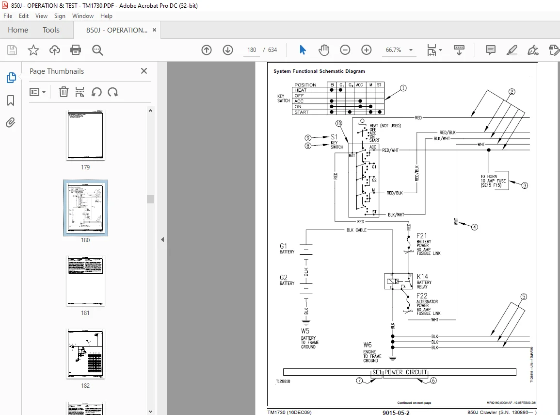
System Functional Schematic, Wiring Diagram, and Component Locat191
System Functional Schematic and Section Legend—90L197
System Functional Schematic, Wiring Diagram, and Component Locat211
System Functional Schematic and Section Legend—81L217
JDLink™ System Functional Schematic—If Equipped (SN 153829— )231
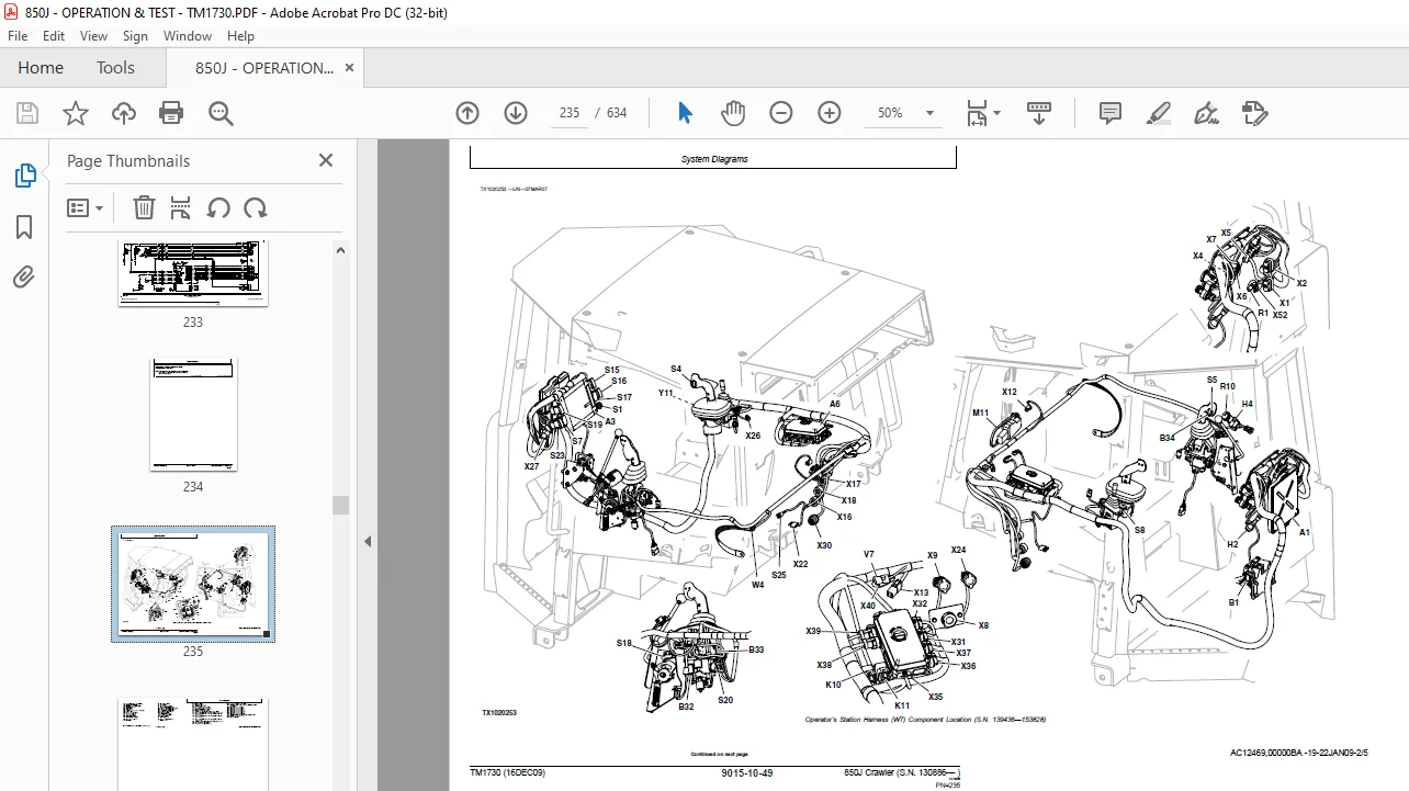
Operator’s Station Harness (W7) Component Location234
Operator’s Station Harness (W7) Wiring Diagram239
Canopy Roof Harness (W8) Component Location254
Canopy Roof Harness (W8) Wiring Diagram257
Cab Roof Harness (W9) Component Location260
Cab Roof Harness (W9) Wiring Diagram263
Engine Harness (W10) Component Location267
Engine Harness (W10) Wiring Diagram275
Transmission Harness (W11) Component Location285
Transmission Harness (W11) Wiring Diagram291
Air Conditioning Harness (W14) Component Location306
Air Conditioning Harness (W14) Wiring Diagram309
Radio Harness (W15) Component Location311
Radio Harness (W15) Wiring Diagram312
IGC Machine Harness (W21) and IGC Cab Harness (W22) Component Lo315
Integrated Grade Control (IGC) Machine Harness (W21) Wiring Diag317
Integrated Grade Control (IGC) Cab Harness (W22) Wiring Diagram322
Pressure Sensor Harness (W27) Wiring Diagram324
JDLink™ System Harnesses (W30, and W31) Component Location—If Eq324
Machine Information Gateway (MIG) Harness (W30) Wiring Diagram—I327
GlobalTRACS® Terminal (GTT) Harness (W31) Wiring Diagram—If Equi331
Sub-System Diagnostics335
Starting and Charging Circuit Theory of Operation335
Controller Area Network (CAN) Theory of Operation339
Engine Control Unit (ECU) Circuit Theory of Operation—90L341
Engine Control Unit (ECU) Circuit Theory of Operation—81L347
Transmission Control Unit (TCU) Circuit Theory of Operation349
CAN Monitor Unit (CMU) Circuit Theory of Operation355
Integrated Grade Control (IGC) Theory of Operation—If Equipped357
References361
Electrical Component Specifications361
Service ADVISOR™ Diagnostic Application367
Service ADVISOR™ Connection Procedure367
Reading Diagnostic Trouble Codes with Service ADVISOR™ Diagnosti368
JDLink™ Connection Procedure—If Equipped (SN 153829— )370
CAN Monitor Unit (CMU) Menu Structure—Service Mode371
Integrated Grade Control (IGC) Checks—If Equipped375
IGC System Checks375
Integrated Grade Control (IGC) Diagnose Malfunctions—If Equipped380
Waves in Graded Surface397
Alternator Test Procedure399
Transmission Control Unit (TCU) Calibration400
Wire Harness Test401
Decelerator/Brake Pedal Adjustment401
Engine Speed Control Remove and Install402
Rotary Sensor Remove and Install402
Transmission Control Lever (TCL) Adjustment403
Bussed Sensor Connectors (X6 and X7) Diagnostics405
Engine Control Unit (ECU) Remove and Install407
Replace WEATHER PACK WEATHER PACK is a trademark of Packard Elec408
Install WEATHER PACK WEATHER PACK is a trademark of Packard Elec409
Replace DEUTSCH DEUTSCH is a trademark of the Deutsch Co™ Conne410
Replace DEUTSCHDEUTSCH is a trademark of Deutsch Co™ Rectangula411
Install DEUTSCH DEUTSCH is a trademark of the Deutsch Co™ Conta412
Replace CINCHCINCH is a trademark of the Cinch Co™ Connectors413
Install CINCHCINCH is a trademark of the Cinch Co™ Contact415
Repair 32 and 48 Way CINCHCINCH is a trademark of the Cinch Co™416
Replace (Pull Type) Metri-Pack™ Connectors419
Replace (Push Type) Metri-Pack™ Connectors420
Hydraulics421
Theory423
Hydraulic System Operation423
Hydraulic Pump Operation424
Hydraulic Control Valve Operation427
Hydraulic Control Valve Operation—IGC429
Load Sense Circuit Operation435
Load Sense Isolator Operation435
Circuit Relief Valve with Anticavitation Operation436
Hydraulic System Relief Valve Operation437
Hydraulic Oil Filter Manifold Operation438
Blade Angle Operation441
Ripper Operation445
Ripper Operation with IGC Controlled Auxiliary Valve449
Quick-Drop Valve Operation453
Diagnostic Information455
Hydraulic System Schematic455
Hydraulic System Schematic—IGC467
Hydraulic System Schematic—IGC with Auxiliary Valve469
Main Hydraulic Component Location471
Ripper Ready Hydraulic Component Location473
Winch Ready Hydraulic Component Location474
Main Hydraulic Component Location—IGC475
Hydraulic System Diagnose Malfunctions477
Oil Overheats Diagnostic Procedure482
Hydraulic System Diagnose Malfunctions—IGC484
Blade Response Not Smooth Diagnostic Procedure—IGC491
Tests493
JT02156A Digital Pressure/Temperature Analyzer Installation493
JDG1770 Ultra CleanUltra Clean is a trademark of Ultra Clean Tec493
Hydraulic Oil Cleanup Procedure493
Hydraulic System Relief Valve Test494
Hydraulic System Relief Valve Test—IGC495
Circuit Relief Valve Test497
Circuit Relief Valve Test—IGC498
Pump Load Sense Differential and System Pressure Test and Adjust499
Pump Load Sense Differential and System Pressure Test and Adjust500
Lift and Tilt Cylinder Function Drift Test502
Hydraulic Cylinder Drift Test503
Cylinder Leakage Test504
Pressure Reducing Valve Pressure Test and Adjustment505
Blade Down Accumulator Hydraulic Discharge505
Blade Down Accumulator Precharge Test506
Hydraulic Pump Flow Test507
Hydraulic Pump Case Drain Test508
Hydrostatic System510
Theory of Operation511
Hydrostatic System511
Transmission Control Circuit Operation (Flow Chart)512
Charge Pump Operation513
Hydrostatic Charge Oil Filter Operation514
Neutral Charge Relief Valve Operation515
Multi-Function Valve Operation516
Hydraulic Integrated Circuit (HIC) Valve Operation518
Park Brake Valve Operation519
Oil Cooler and Reservoir Bypass Operation520
Pump Pressure Control Pilot (PCP) Operation521
Pump Displacement Control Valve (PDCV) Operation522
Hydrostatic Pump Operation523
Flushing Valve and Operating Charge Relief Valve Operation524
Hydrostatic Motor Operation525
Hydraulic Reversing Fan Drive Operation527
Hydraulic Non-Reversing Fan Drive Operation529
Hydraulic Fan Return Filter Operation532
Diagnostic Information535
Overheating—Flowchart535
Low Charge Pressure—Flowchart536
Mistrack/Indexes—Flowchart537
Machine Will Not Reach Full Speed—Flowchart538
Low Power—Flowchart539
Engine Starts But One Or Both Tracks Will Not Move—Flowchart540
TCU Calibration Problems—Flowchart541
Hydrostatic System Component Location543
Park Brake System Component Location546
Hydrostatic System Schematic—Neutral (Park Brake On)549
Hydrostatic System Diagram—Neutral (Park Brake On)553
Hydrostatic System Diagram—Reverse (Slow Speed)555
Hydrostatic System Diagram—Forward (Fast Speed)557
Tests559
JT02156A Digital Pressure/Temperature Analyzer Installation559
JDG1770 Ultra CleanUltra Clean is a trademark of Ultra Clean Tec559
Machine Supporting Procedure560
Transmission Oil Warm-Up Procedure561
Releasing Park Brake to Tow the Machine563
Hydrostatic Pump and Motor Initial Start-Up Procedure564
Hydrostatic Pump Flushing Procedure565
Hydraulic Oil Cleanup Procedure565
Pressure Control Pilot (PCP) Manual Override Test566
Pressure Control Pilot (PCP) Test567
Pressure Control Pilot (PCP) Internal Adjustment569
Multi-Function Relief Valve Test571
Transmission Efficiency Test574
Neutral Charge Relief and Operating Charge Relief Pressure Test577
Pump Displacement Control Valve (PDCV) Neutral (Null) Adjustment580
Pump Servo Pressure Test582
Motor Displacement Control Valve (MDCV) Adjustment584
Hydrostatic Motor Min/Max Angle Servo Piston Pressure Test586
Charge Pump Flow Test588
Charge Pressure Sensor Test (SN 133015—)589
Hydrostatic Oil Cooler Bypass Test591
Hydrostatic Oil Reservoir Bypass Test593
Park Brake Test595
Park Brake Relief Valve Test599
Cab Tilt Relief Valve Test599
Hand Pump Bleed Procedure600
Fan Pump Pressure Test601
Fan Pump Flow Test602
Fan Motor Speed Test604
Fan Motor Case Drain Test605
Heating and Air Conditioning607
Theory of Operation609
Air Conditioning System Cycle Of Operation609
Diagnostic Information611
Diagnose Air Conditioning System Malfunctions611
Diagnose Heater System Malfunctions614
Tests617
Proper Refrigerant Handling617
R134a Refrigerant Cautions617
R134a Oil Charge Capacity617
R134a Refrigerant Charge Capacity617
Refrigerant Hoses And Tubing Inspection618
R134a Air Conditioning System Test619
Operating Pressure Diagnostic Chart621
Air Conditioner Low Pressure Switch Test623
Air Conditioner High Pressure Switch Test624
Freeze Control Switch Test625
Leak Testing625
Page Number 5
Section 9000 7
Group 01 9
Section 9001 23
Group 10 25
Group 20 37
Group 30 39
Group 40121
Group 50137
Section 9005139
Group 10141
Section 9010155
Group 05157
Group 15159
Group 25175
Section 9015178
Group 05179
Group 10187
Group 15335
Group 20361
Section 9025421
Group 05423
Group 15455
Group 25493
Section 9026510
Group 05511
Group 15535
Group 25559
Section 9031607
Group 05609
Group 15611
Group 25617
S.M 4/1/25