John Deere 9540 9560 9580 9640 9660 9680 WTS CWS Combines Repair Manual 201130812 – PDF DOWNLOAD
Original price was: $76.95.$29.95Current price is: $29.95.
John Deere 9540 9560 9580 9640 9660 9680 WTS CWS Combines Repair Manual 201130812 – PDF DOWNLOAD
Description
John Deere 9540 9560 9580 9640 9660 9680 WTS CWS Combines Repair Manual 201130812 – PDF DOWNLOAD
DESCRIPTION:
John Deere 9540 9560 9580 9640 9660 9680 WTS CWS Combines Repair Manual 201130812 – PDF DOWNLOAD
INTENDED USE:
This combine is designed solely for use in customary agriculture or similar operations. Use in any other way is considered as contrary to the intended use. The manufacture accepts no liability for damage or injury resulting from misuse, and these risks must be borne solely by the user.
- Compliance with and strict adherence to the conditions of operation, service and repair as specified by the manufacturer also constitute essential elements for the intended use. READ THIS MANUAL carefully to learn how to operate and service your machine correctly.
- Failure to do so could result in personal injury or equipment damage. This manual and the safety signs on your machine may also be available in other languages (see your John Deere dealer to order). THIS MANUAL SHOULD BE CONSIDERED a permanent part of your machine and should remain with the machine when you sell it. MEASUREMENTS in this manual are given in both metric and customary U.S. unit equivalents.
- Use only correct replacement parts and fasteners. Metric and inch fasteners may require a specific metric or inch wrench. RIGHT-HAND AND LEFT-HAND sides are determined by facing the direction of forward travel. WRITE PRODUCT IDENTIFICATION NUMBERS (P.I.N.) in the Specification or Identification Numbers section.
- Accurately record all the numbers to help in tracing the machine should it be stolen. Your dealer also needs these numbers when you order parts. File the identification numbers in a secure place off the machine.
TABLE OF CONTENTS:
John Deere 9540 9560 9580 9640 9660 9680 WTS CWS Combines Repair Manual 201130812 – PDF DOWNLOAD
Contents 3
Predelivery Inspection 11
Predelivery Inspection 11
Identification View 12
Combine 12
Safety 13
Recognize Safety Information 13
Follow Safety Instructions 13
Look for Supplemental Information 14
Observe Road Traffic Regulations 14
Check Machine Safety 14
Fire Extinguisher 15
Prevent Machine Runaway or Unexpected Movement 15
Driving the Combine 16
Road Safety Switch 16
Emergency Exit 17
Use Safety Lights and Devices 17
Keep Riders and Children Off Machine 17
Ballasting for Safe Ground Contact 18
Radio Aerial 18
Parking and Leaving the Combine 19
Work In Ventilated Area 19
Store Attachments Safely 19
Handle Fuel Safely—Avoid Fires 20
Prepare for Emergencies 20
Wear Protective Clothing 20
Stay Clear of Harvesting Units 21
Keep Hands Away From Knives 21
Transport Combine With Header Safely 21
Avoid Contact With Moving Parts 22
Cleaning the Grain Tank and Removal of Blockages 22
Stay Clear of Rotating Drive lines 22
Guards and Shields 23
Practice Safe Maintenance 23
Prevent Machine Damage When Welding 23
Service Machines Safely 24
Support Machine Properly 24
Re-torque Wheel Nuts 24
Remove Paint Before Welding or Heating 25
Avoid Heating Near Pressurized Fluid Lines 25
Avoid High-Pressure Fluids 26
Protect Against High Pressure Spray 26
Prevent Battery Explosions 27
Prevent Acid Burns 27
Service Tires Safely 28
Dispose of Waste Properly 28
Service Cooling System Safely 29
Remove Accumulated Crop Debris 29
Safety Decal Location 30
Pictorial Safety Signs 30
Operator’s Manual 30
Repair and Maintenance 30
Parking Brake 31
Front Access Ladder and Platform 31
Avoid Motor Vehicle Collisions 31
Rear Access Ladder and Service Platform 32
Fire Extinguisher 32
Grain Tank 32
Header Drive Guard 32
Feeder House Shield 33
Feeder House Conveyor Chain 33
Feeder House Safety Stop 33
Elevators 33
Chopper 34
Grain Tank Unloading Auger 34
Hydraulic System 34
Cooling System 35
Rotary Screen and Radiator Fan 35
Feeder House Tilt Frame 35
Electrical Power Lines 35
Rotary Screen 36
Emergency Exit 36
Rear Door 36
Controls and Instruments 37
General View of Controls and Instruments 37
Switch and Knob Colors 38
Armrest Control Panel 39
Armrest Control Panel (Continued) 40
Multi-Function Lever 41
Corner Post 42
Overhead Control Panel 44
Steering Column 45
Header Engage / Electro Feeder House Reverser Switch (Yellow) 46
Separator Engage Switch (Yellow) 47
Operating Adjustments and Controls 47
DIAL-A-SPEED™ Knob (Black) (Optional) 48
Engine Speed Switches (Orange) 50
Response Rate Control For Automatic Functions And Feeder House Reaction Speed Knobs 50
Grain Tank Cover Switch (Black) 51
Operating Adjustments and Controls 52
Road Transport Disconnect Switch 52
Ground Drive and Engine Speed Switches 53
Four Wheel Drive Engage 53
Operating Adjustments and Controls 54
Manual Reel Speed Switch 54
Concave Clearance Switch 54
Cylinder Speed Switch (Black) 55
Cleaning Fan Speed Switch (Black) 55
Chopper Vane Adjust Switch (Black) (Optional) 56
Manual Leveling Control Switch (HILLMASTER II) (Optional) 56
Automatic Leveling Control Switch (HILLMASTER II) (Optional) 57
Operating With HILLMASTER II Leveling System (Optional) 58
Daily Preparations Before Driving HILLMASTER II Combine (Optional) 59
Operating With Automatic Leveling Control (Optional) 60
Operating With Manual Leveling Control (Optional) 61
Multi-Function Lever 62
Multi-Function Handle 62
Quick Stop Switch 62
Unloading Auger Swing Switch 63
Multi-Function Lever 64
Unloading Auger Drive Switch 64
Activation Buttons (Black) 65
Activation Button Allocation 66
Reel Lift/Reel Fore and Aft Switch (Black) 67
Multi-Function Handle 67
Header Lift Switch 67
Multi-Function Lever 68
Lateral Tilt Switch 68
CLIMATRAK™Automatic Temperature Control 69
Outside Mirror Control Switch 70
Mirror Heater Switch 70
Windshield Wiper and Windshield Washer (Optional) 71
Gear Shift Lever 71
Horn 72
Indicator Lights 72
Start Switch 73
Shifting Feeder House/Header Reverser 74
Warning Devices and Monitors 75
Overhead Warning Display Panel 75
Unloading Auger On 76
Low Fuel 76
Overhead Warning Display 76
Park Brake On 76
Main Gearcase Drive Filter 76
Main Gearcase Temp 77
Hydraulic Oil Temp 77
Voltage 77
ENG (Engine) Air Filter 78
Separator Plugged 78
Tilt Limit (HILLMASTER II ) 78
Grain Tank Cover Indicator 79
Grain Tank Full 79
Grain Tank (3/4) Full 79
Hydro Charge Pressure 80
Main Gearcase Lube Pressure 80
Overhead Warning Display 80
ENG (Engine) Temperature 80
ENG (Engine) Oil Pressure 81
High Beam Indicator 81
Straw Chopper (Optional) 81
Grain Separator 82
Auger Conveyor 82
Grain Elevator 82
Tailings Elevator 82
Cylinder Speed 83
Engine Speed 83
HEADERTRAK Control Module 84
HEADERTRAK Control Display 85
Description of HEADERTRAK Control System 86
Stubble Height Control 90
Return To Cut 92
Header Width 94
DIAL-A-SPEED 95
Lateral Tilt 96
Header Ground Pressure 98
Reel Position Resume100
VISIONTRAK™Display Module101
VISIONTRAK Display Control Switches101
Calibration Switch102
Up/Down Arrow Switch102
Seed Size Switch102
Adjustable Deck Plate Position (Optional)103
Tailings Sensor Display104
Tailings Sensor Display Operational Check105
VISIONTRAK Performance Monitor106
Shoe Loss107
Separator Loss107
Total Loss108
Preliminary Adjustments on Combine108
VISIONTRAK Performance Monitor (General Information)109
Operating VISIONTRAK Performance Monitor110
Additional Control Switches (VISIONTRAK Monitor)112
Back Arrow Switch113
Diagnostics Switch113
Enter Switch113
Area Counter Switch113
Area Counter Operation114
Triple Display Tachometer115
Control Switches116
Engine Speed Switch116
Cylinder Speed Switch116
Concave Clearance Switch117
Up/Down Arrow Switch (Display Line Select)117
Clock Select Switch117
Fan Speed Switch117
Fixed Speed Feeder House Switch118
Engine Hours/Separator Hours Switch118
Fuel Gauge119
Coolant Temperature Gauge119
Digital Display Lines120
Tachometer Service Information121
Diagnostic Icon122
Low Shaft Speed Monitor (General Information)123
Low Shaft Speed Monitor Troubleshooting124
Calibration Procedures125
When to Calibrate125
How Diagnostic Address Information is Displayed125
Diagnostic Trouble Codes126
Header Width Calibration145
Header Calibration147
Angle Sensor Calibration152
HEADERTRAK Sensor Cable Adjustment156
Machine Harvesting Threshold Calibration157
Float Calibration (For Header With Sensors)161
Float Calibration (For Header Without Sensors)164
Concave Sensor Zero Calibration167
Area Counter Enable Calibration170
Field Area Counter Clear Calibration172
Field Total Area Counter Clear Calibration173
Deck Plate Sensor Zero Calibration175
Tailings Monitor Calibration179
Chopper Vane Angle Calibration180
Clock Calibration183
Clear Service (SEU) Indicator186
Operator’s Station188
Access Ladder to Operator’s Cab188
Cab Ladder Positions188
Cab Landing Safety Chains189
Washing Cab Windows, Servicing Head Lights and Wiper189
Right-Hand Side Cab Access190
Grain Tank Window/Rear Cab Window Cleaning190
Armrest Storage Box191
Manual Storage191
GREENSTAR™ Printer (Optional)191
GREENSTAR (Attachment)192
Cooling Compartment/Recirculation Filter192
Emergency Exit193
Cab Interior Lights193
Auxiliary Power Outlet Strip and SERVICE ADVISOR™ Diagnostic Connector193
Operator’s Seat194
Field Office194
Cooling Compartment194
Operator’s Seat195
Operator’s Seat196
Seat Suspension 196
Adjusting, LH Armrest and Seat Back197
Adjusting RH Armrest and Control Console197
Steering Column198
Wheel Height Adjustment198
Steering Column Tilt Adjustment198
Manual Parking Brake199
Brake Pedals199
Filling Windshield Washer Reservoir (Attachment)199
Lights and Signals200
Light Switches200
Cab Interior Lights200
Dimmer Switch201
Warning Lights202
Road Lights203
Field Lights205
Stubble and Residue Lights207
Unloading Auger Rear Tail/Stop Light207
Turn Signals208
Exit Lighting208
Unloading Auger Light209
Work Lights (Optional)210
Rear Residue Discharge Lights211
Cleaning Shoe Lights211
Service Power Receptacles (Optional)212
Prestarting Checks213
Engine Oil Level213
Hydrostatic/Hydraulic Oil Levels214
Coolant Level214
Fuel Level215
Fuel System (9540 Combine)215
Fuel System215
After Long Storage Period216
Tires216
Lubricate Combine217
Checks in Operator’s Cab217
Start Switch218
Operating the Engine219
Safety Rules for Starting Engine219
Starting the Engine220
Warming up Engine223
Breaking-In Engine224
Break-In Check First 100 Hours226
Break-In Check After 100 Hours226
Hot Weather Operation227
Cold Weather Operation228
Starting the Engine by Means of a Booster Battery229
Stopping the Engine230
Stalling of Engine230
Driving and Transporting the Combine231
Starting the Engine231
Steering and Driving231
Manual Parking Brake231
Brake Pedals232
Engaging a Gear232
Road Safety Switch232
Adjusting Engine Speed233
Raising Header233
Forward and Reverse Travel233
Reverse Travel Alarm234
Choosing Correct Ground Speed234
Avoid Overheating of Hydrostatic System235
Transport Information235
Transporting Under Own Power236
Ground Drive and Engine Speed Switches237
Four Wheel Drive Engage237
Towing the Combine238
Attaching Machine Safely239
Trailer Hitch240
Transporting Combine on a Trailer240
Unloading Auger Transport Protection243
Wheels, Axles and Additional Weights244
Service Tires Safely244
Tire Maintenance244
Rear Wheel Bolt Torque245
Drive Wheel Bolt Torque245
Mounting Tires246
Changing Tires247
Using Liquid Weight247
Drive Wheel Starter Stud247
Wheel Offset248
Jacking Locations249
Harvesting Hints250
Choice of Harvesting Time250
Harvesting Tips250
Automatic Combine Adjust System252
Automatic Combine Adjust System252
Crops253
Automatic Combine Adjust Display Settings254
Adjusting Predefined Settings255
Factory Crop 2 (WHEAT 2) and Personal CROP1 — CROP5 Setting Changes (Automatic Calibration)256
Factory Crop 2 (WHEAT 2) and Personal CROP1 — CROP5 Setting Changes (Manual Calibration)257
Crop Settings and Seed Loss Charts259
Crop Settings259
Seed Loss Chart (Platforms)262
Soybean Loss Chart (Row-Crop Heads)263
Combine and Corn Head Check List264
Corn Kernel Loss Chart265
Power Shutdown Procedure266
Combine Cleanout267
Cleaning Out the Combine267
Feeder House275
Hydraulic Cylinder Safety Stop275
Feeder House Side Shields275
Feeder House Doors276
Cylinder Top Access Door276
Bottom Feeder House Door and Feedplate Seal Support277
Stone Trap278
Adjusting Fore/Aft Tilt Frame278
Adjusting Feeder Conveyor Chain279
Removing Conveyor Chain Links280
Checking Feeder House Conveyor “Float”280
Drum Height Adjustment281
Changing Feeder Conveyor Speed281
Adjusting Feeder Conveyor Drive Chain282
Slip Clutch283
Feeder House Top Shaft Stripper Adjustment284
Feeder House Top Shaft Sprockets284
Adjusting Fixed Speed Feeder House Belt285
HEADERTRAK Tilt Indicator285
Removing Header from Feeder House286
Separator287
Left-Hand Drives287
Right-Hand Drives289
Dual-Range POSI-TORQ Cylinder Drives290
Single-Range Cylinder Drive291
Dual Range Cylinder Drive Shear Bolts291
High-Range Direct Drive (480-980 RPM)292
Low Range (Reduced-Drive) (240-480 RPM)292
Unplugging Cylinder with Breaker Bar293
Power Unplugging of Cylinder294
Setting Cylinder Access Door to Cylinder295
Cylinder Vibration295
Rear Concave Inserts (Corn Combines)296
Front Concave Closure Plates (Attachment)297
Rear Concave Closure Plates (Attachment)297
Second Concave Curtain (Attachment)298
Power Separator298
Straw Walkers/Power Separator Access Door298
75 Percent Beater Speed (Optional)299
Separator Curtains299
Straw Walker Extension Pans299
Straw Walker Sunflower Flaps300
Slow Speed Cleaning Fan Drive (Attachment)300
Chaffer Fingers Storage300
Using Chaffer Fingers301
Precleaner Tool Storage301
Adjusting Precleaner301
Adjusting Chaffer, Chaffer Extension and Sieve302
Chaffer Finger Bar Cover (Attachment)302
Clean Grain Elevator Top Access Cover for Drives303
Perforated Screens (Attachment)303
Tailings Elevator Paddles304
Separator Countershaft Strips304
Tailings Elevator Slip Clutch304
Chopper and Spreader305
Chopper (General Information)305
Adjusting Chopper Vanes (Manual)306
Adjusting Chopper Vanes (Electrical)306
Adjusting Knives307
Chaff Spreader (Optional)307
Chop to Drop307
Raising and Lowering Chopper Vane Board308
Adjusting Spreader Disk Vanes309
Removing the Chaff Spreader310
Grain Tank and Unloading System311
Grain Tank/Engine Ladder311
Grain Tank Drain Holes311
Operating Grain Tank Covers312
Adjusting Grain Tank 3/4 Indicator313
Adjusting Grain Tank Full Indicator314
Grain Tank Unloading Auger Covers (Optional) (Standard on Rice Combines)314
Cross Auger Drive Shear Bolt315
Grain Tank Loading Auger Deflector315
Adjusting Unloading Auger Drive Cylinder316
Replacing Unloading Auger Drive Cylinder316
Vertical Adjustment of Auger Support Stud317
Adjust Swing Cylinder Eyebolt317
Reduced Speed Unloading System (Optional)318
Fuels and Lubricants319
Diesel Fuel319
Storing Fuel319
Fill Fuel Tank320
Diesel Engine Coolant321
Liquid Coolant Conditioner322
Diesel Engine Break-In Oil322
Diesel Engine Oil323
Extended Diesel Engine Oil Service Intervals323
Hydrostatic Drive System, Main Hydraulic System and Main Engine Gear Case Oils324
Transmission, Final Drives, Feeder House Reverser, Dual-Range Cylinder Drive, Primary Countershaft and Loading Auger Elevator324
Straw Walker Gearcase325
Grease325
Brake Fluid326
Lubricant Storage326
Alternative and Synthetic Lubricants326
Capacities327
Lubrication and Maintenance328
Service During the Break-In Period (First 100 Hours)328
Service Intervals328
Lubrication Symbols331
10 Hours or Daily332
10 Hours or Daily334
50 Hours or Weekly335
50 Hours or Weekly336
50 Hours or Weekly337
50 Hours or Weekly338
50 Hours or Weekly (HILLMASTER II Only)339
100 Hours340
200 Hours341
200 Hours342
250 Hours or Yearly343
400 Hours or Yearly345
400 Hours or Yearly346
400 Hours or Yearly347
400 Hours or Yearly348
400 Hours or Yearly349
400 Hours or Yearly350
400 Hours or Yearly351
400 Hours or Yearly352
400 Hours or Yearly354
800 Hours or Every Two Years355
2000 Hours356
2000 Hours357
2000 Hours358
As Required359
As Required360
Replace Engine Crankshaft Damper—4500 Hours or Five Years361
Cleaning Combine361
Shields362
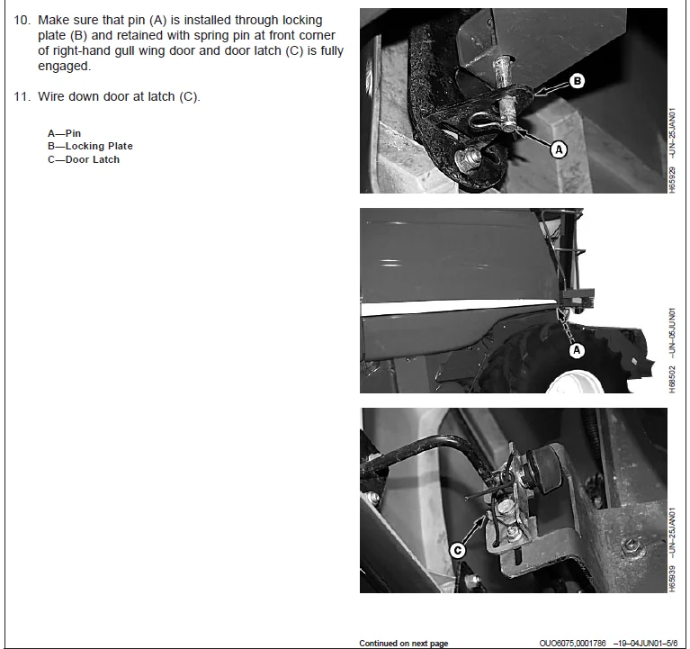
Left-Hand and Right-Hand Gull Wing Doors362
Right-Hand Rear Shield364
Left-Hand Side Separator Shields365
Right-Hand Side Separator Side Shield365
Cleaning Composite Panels366
Service – Engine367
Rear Ladder and Landing367
Engine Compartment Door367
Cleaning Engine Compartment367
Belt Shield368
Engine Access Panel368
Fuel System368
Do Not Modify Fuel System369
Handle Fuel Safely—Avoid Fires369
Check Engine Oil370
Fuel Tank and Cap370
Draining Fuel Tank371
Replacing Fuel Filter (9540 Combine Only)371
Replacing Fuel Filter372
Water Separator Filter Replacement (9540 Combine Only)373
Draining Water Separator373
Bleeding Fuel Lines373
Bleeding Engine Fuel Filter (9540 Combine Only)374
Bleeding Combine Fuel System375
Drain Cooling System376
Filling Radiator378
Winterize Cooling System378
Replacing Engine Fan Belt379
Engine Accessory Drive Belt Routing (68 Liter Engine)380
Engine Accessory Drive Belt Routing (81 Liter Engine)380
Replace Engine Accessory Drive Belt381
Rotary Screen Belt Routing383
Replacing Rotary Screen Drive Belt383
Cleaning Rotary Screen, Oil Cooler, Condenser, Radiator and Charge Air Cooler385
Adjust Rotary Screen Knife Comb386
Removing Air Cleaner Filters387
Inspecting Element387
Cleaning Element388
Washing Element388
Service – Feeder House389
Hydraulic Cylinder Safety Stop389
Replacing Fixed Speed Feeder House Belt390
Removing Conveyor Chain Links391
Adjusting Feeder Conveyor Drive Chain391
Adjusting Fixed Speed Feeder House Belt392
Service – Separator393
Adjusting Cylinder Drive Gap393
Aligning Cylinder Drive394
Adjusting Cylinder Belt Idler395
Replacing Cylinder Intermediate Belt396
Replacing Cylinder Belt397
Second Concave Adjustment398
Adjusting Beater Belt Idler398
Replacing Beater Belt399
Adjusting Secondary Countershaft Belt399
Replacing Secondary Countershaft Belt400
Replacing Power Separator Belt401
Adjusting Feeder House Drive/Reel Pump Belt401
Replacing Feeder House/Reel Pump Belt402
Adjusting Straw Walker Gearcase Belt402
Adjusting Straw Walker Plugging Switch403
Adjusting Cleaning Shoe Auger Gears403
Replacing Cleaning Shoe Belt404
Replacing Cleaning Fan Belt405
Replacing Clean Grain Elevator Belt406
Adjust Clean Grain Elevator Drive Belt406
Adjusting Clean Grain Elevator Chain407
Replacing Tailings Auger and Elevator Drive Belt407
Adjusting Tailings Elevator Belt408
Adjusting Tailings Elevator Drive Chain408
Adjusting Tailings Elevator Paddle Chain409
Adjusting Upper Tailings Auger Drive Chain409
Service – Chopper and Spreader410
Replacing Knife Sections410
Remove and Replace Straw Chopper Blades411
Remove and Replace Counter Knife Bank412
Replacing Chopper Belt412
Service – Grain Tank and Unloading414
Adjusting Grain Tank Cross Auger Drive414
Replacing Unloading Auger Drive Belt414
Aligning Unloading Auger Drive415
Adjusting Unloading Auger Drive Cylinder416
Replacing Unloading Auger Drive Cylinder417
Vertical Adjustment of Auger Support Stud417
Adjust Swing Cylinder Eyebolt417
Service – Electrical System419
Specifications, Electrical System419
Batteries419
Dangers When Handling Batteries419
Battery Service420
Checking Electrolyte Level420
Checking Specific Gravity421
Battery Switch421
Connecting Booster Batteries422
Installing Batteries and Connecting to Correct Poles422
Welding on Machine423
Relays423
Power Distribution Board Relay Identification424
Engine Compartment Relay Panel Fuse Identification425
Engine Compartment Relay Panel Identification426
Safety Rules When Replacing Halogen Bulbs427
Replacing Bulbs427
Cab Head Light Bulb Replacement and Adjustment428
Replacing Stubble Light (Optional) Bulb429
Replacing Field Light Bulb429
Replacing Side Finder Light Bulb430
Replacing Grain Tank Light Bulb430
Replacing Cleaning Shoe Light Bulb431
Replacing Warning Light Bulb431
Replacing Turn Signal Indicator Light Bulb432
Replacing Dome and Console Light Bulb432
Replacing Warning Display Panel Light Bulb433
Observe Electrical Precautions433
Basic Electrical Component Handling / Precautions For Vehicles Equipped With Computer Controlled Systems434
Starter434
Alternator and Voltage Regulator435
Header Drive Electromagnetic Clutch435
Antenna Mounting436
Service – Hydraulic System437
Hydraulic System (General Information)437
Hydraulic System Cleanliness438
Accumulator (General Information)439
Valve for Raising/Lowering Header (Proportional Valve)439
Service – Ground Speed Drive440
Adjusting Gearshift Linkage440
Brake Fluid440
Brake System441
Cleaning Hydrostatic Oil Cooler441
Service – Air Conditioning and Heater442
Observe Air Conditioning Precautions442
CLIMATRAK Air Conditioning System (General Information)442
Cleaning Fresh Air Filter and Recirculating Filter443
Removing Evaporator Filter443
Cleaning Cab Roof Inlet Panel444
Cleaning Condenser444
Engine Accessory Drive Belt Routing (68 Liter Engine)445
Engine Accessory Drive Belt Routing (81 Liter Engine)445
Removing Compressor Drive Belt446
High Pressure Switch448
Low Pressure Switch448
Trouble Shooting449
Feeder House449
Separator450
Hydrostatic Ground Drive454
4-Wheel Drive (Optional)457
Steering457
Brakes458
Engine459
Heater463
Air Conditioning464
Storage466
Preparing Combine for Storage466
Removing Combine from Storage467
Specifications468
Operating Speeds468
Whole Body Vibration470
Sound Level470
Turning Radius470
Specifications – 9540 Combine Only471
Specifications – 9560, 9580, 9640, 9660, 9680 Combines473
Dimensions474
Dimension Reference Points475
Metric Bolt and Cap Screw Torque Values476
Unified Inch Bolt and Cap Screw Torque Values477
Safety Note Regarding the Subsequent Installation of Electrical and Electronic Appliances and/or Components478
Declaration of Conformity479
Machine Identification Numbers480
Type Plates480
Combine Type Plate480
Engine Serial Number480
Hydrostatic Drive Unit Pump481
Hydrostatic Drive Unit Motor481
2 Speed 4-Wheel Drive Motor481
Engine Gearcase482
Transmission482
John Deere Service Keeps You On The Job491
John Deere Parts491
The Right Tools491
Well-Trained Technicians491
Prompt Service491
IMAGES PREVIEW OF THE MANUAL:
JOHN DEERE 9540 9560 9580 9640 9660 9680 WTS CWS COMBINES REPAIR MANUAL 201130812 – PDF DOWNLOAD:
PLEASE NOTE:
- This is the SAME MANUAL used by the dealerships to diagnose your vehicle
- No waiting for couriers / posts as this is a PDF manual and you can download it within 2 minutes time once you make the payment.
- Your payment is all safe and the delivery of the manual is INSTANT – You will be taken to the DOWNLOAD PAGE.
- So have no hesitations whatsoever and write to us about any queries you may have : heydownloadss @gmail.com
S.V