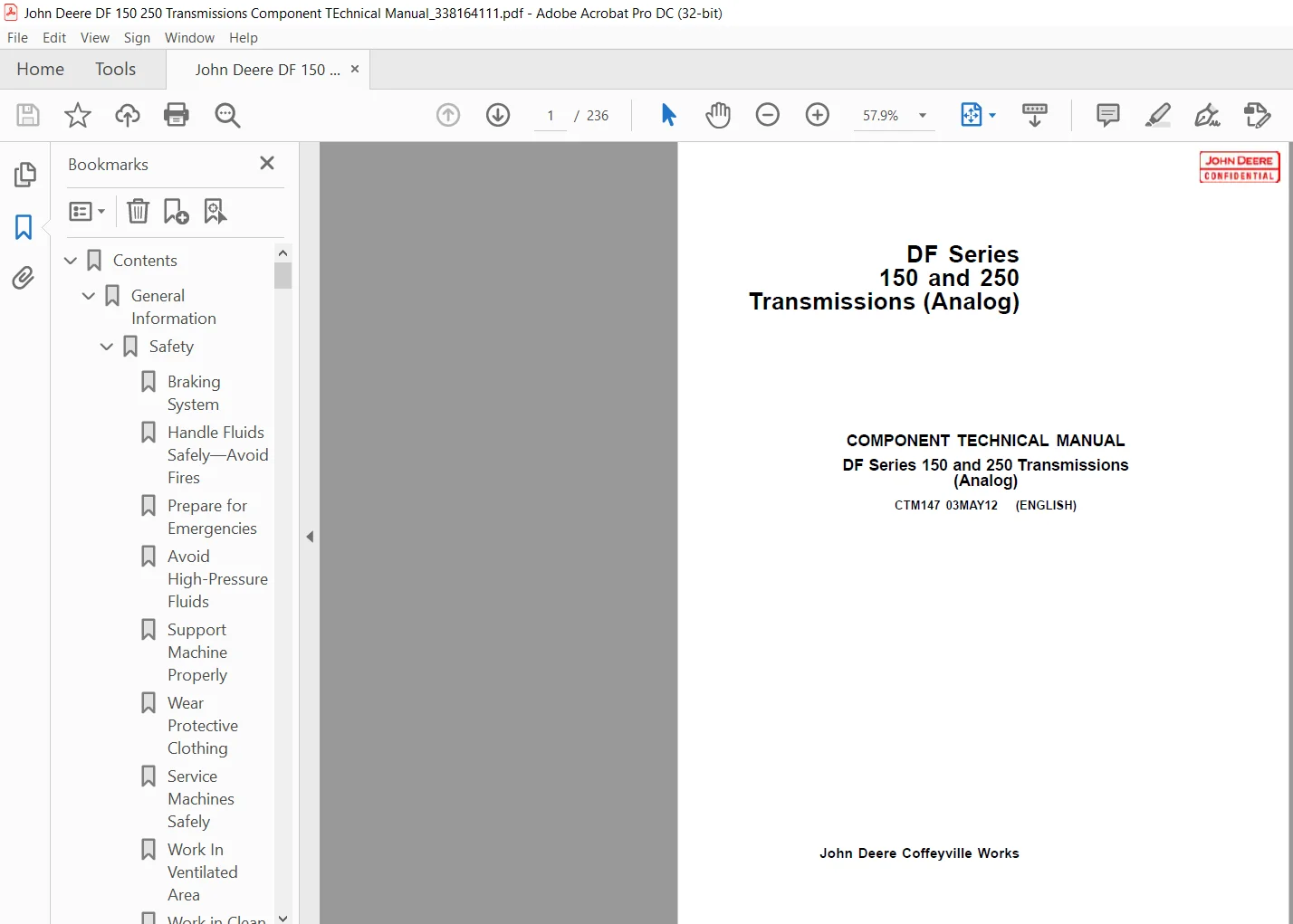
John Deere DF 150 & 250 Transmissions Component Technical Manual – PDF DOWNLOAD
Original price was: $76.95.$27.95Current price is: $27.95.
John Deere DF 150 & 250 Transmissions Component Technical Manual – PDF DOWNLOAD
Description
John Deere DF 150 & 250 Transmissions Component Technical Manual – PDF DOWNLOAD
DESCRIPTION:
John Deere DF 150 & 250 Transmissions Component Technical Manual – PDF DOWNLOAD
Component Technical Manuals (CTM) are concise service guides for specific components. Component technical manuals are written as stand-alone manuals covering multiple machine applications. This manual is written for an experienced technician. Essential tools required in performing certain service work are identified in this manual and are recommended for use.
- Use this component technical manual in conjunction with the machine technical manual. See the machine technical manual for information on component removal and installation, and gaining access to the components. This manual is divided in three parts; general information, repair, and troubleshooting and tests: General information group offers component identification with specification information about the transmission.
- Repair groups contain necessary instructions to repair the component. Troubleshooting and test groups help you identify the majority of routine failures quickly and then allows you to perform certain tests. Information is organized in groups for the various components requiring service instruction. At the beginning of each group are summary listings of all applicable service equipment and tools, other materials needed to do the job, specifications, and torque values.
TABLE OF CONTENTS:
John Deere DF 150 & 250 Transmissions Component Technical Manual – PDF DOWNLOAD
Contents 3
General Information 5
Safety 7
Braking System 7
Handle Fluids Safely—Avoid Fires 7
Prepare for Emergencies 7
Avoid High-Pressure Fluids 7
Support Machine Properly 8
Wear Protective Clothing 8
Service Machines Safely 8
Work In Ventilated Area 9
Work in Clean Area 9
Remove Paint Before Welding or Heating 9
Avoid Heating Near Pressurized Fluid Lines 10
Illuminate Work Area Safely 10
Use Proper Lifting Equipment 10
Practice Safe Maintenance 11
Use Proper Tools 11
Dispose of Waste Properly 12
Live With Safety 12
Park Machine Safely 12
Stay Clear of Rotating Drivelines 13
Prevent Machine Runaway 13
Transmission ldentification, Lubricants, Towing, Storage 15
Identification and Serial Number Plates 15
DF150/250 Transmission SpecificationsWeights will vary depending 16
Transmission and Hydraulic Oil 17
Recommended Lubricants 18
Fill the Transmission with Oil 18
Check and Service Transmission Regularly 18
Intervals for Changing Transmission Oil and Filters 19
Cold Weather Startup 19
Cold Weather Operation 19
Oil Analysis 20
Oil Temperature Warning Signal 20
Towing the Vehicle 20
Put Transmission in Storage 20
Remove Transmission From Storage 20
Install Transmission to the Engine 21
Converter-to-Engine Flywheel Dimensions 22
Engine to Torque Converter Specifications 23
Repair and Adjustments 26
Transmission Mounting 27
Use Proper Lifting Equipment 27
Transmission Lifting Procedure 27
Transmission Repair Stand 28
Mounting DF Series Transmission to Repair Stand 28
Torque Converter 29
Other Material 29
Specifications 29
Remove Torque Converter and Drive Plate Assembly 29
Disassemble and Assemble Drive Plate Group 30
Disassemble Drive Plate Group 30
Assemble Drive Plate Group 31
Disassemble and Assemble 3239 mm (1275 In) Torque Converter wi 32
Disassemble and Assemble 3239 mm (1275 in) Torque Converter wi 33
Remove Front Cover 34
Remove and Install Bearing in Front Cover 34
Remove Turbine Assembly 34
Remove Stator Assembly 35
The Converter Assembly May Contain Either a “Free Stator Assembl 35
Disassemble and Assemble Fixed Stator Assembly 35
Disassemble Fixed Stator Assembly 36
Stator Front and Back Side Identification 36
Assemble Fixed Stator Assembly 37
Disassemble and Assemble Free Stator Assembly 38
Disassemble Free Stator Assembly 39
Assemble Free Stator Assembly 40
Disassemble Converter Impeller 43
Assemble Converter Impeller and Hub 44
Assemble Stator to Impeller 46
Assemble Turbine to Stator 47
Assemble Front Cover to Turbine and Impeller 48
Charge Pump 51
Other Material 51
Specifications 51
Disassemble Suction Tube Group 52
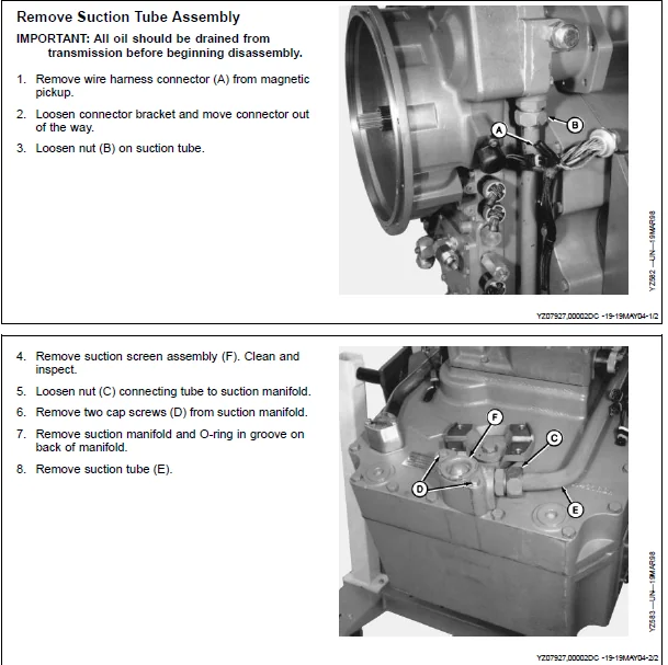
Remove Suction Tube Assembly 53
Assemble Suction Tube Group 54
Install Suction Tube 55
Charge Pump Group 56
Remove Charge Pump Group 57
Remove Driven Gear and Bearing Assembly 58
Disassemble and Assemble Charge Pump Group with Auxiliary Pump D 59
Disassemble Auxiliary Pump Drive Disconnect 60
Assemble Auxiliary Pump Drive Disconnect 61
Install Driven Gear and Bearing Assembly (Charge Pump) 63
Install Charge Pump to Front Cover 63
Front Cover 65
Other Material 65
Specifications 65
Disassemble Front Cover Group 66
Remove Front Cover and Input Assembly 67
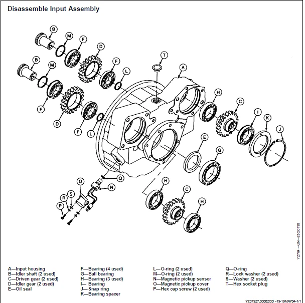
Disassemble Input Assembly 70
Disassemble Front Cover 71
Remove and Disassemble Driven Gears 72
Assemble Driven Gears and Bearings (Charge Pump Side) 72
Remove Idler Gears and Disassemble 73
Assemble Idler Gears 74
Remove Magnetic Pickup 74
Assemble Input Assembly 75
Install Oil Seal and Ball Bearing 76
Install Idler Gears and Bearing Assemblies 77
Install Idler Shafts 78
Install Driven Gear Assembly (Auxiliary Pump Port Side) 80
Install Magnetic Pickup 82
Assemble Front Cover Group 83
Assemble Converter Input Shaft and Stator Tube 84
Install Front Cover Assembly to Main Case Front Housing 86
Control Valve 87
Other Material 87
Specifications 87
Remove and Install Wiring Harness 88
Remove Control Valve Group 89
Disassemble and Assemble Control Valve 90
Install Control Valve Group 91
Cap Screw Tightening Sequence and Torque Specifications 92
Piping Diagram, Converter Driven Transmission, (Without Wet Brak 93
Pressure and Temperature Check Ports (Without Wet Brake) 94
Main Case Front Housing 95
Other Material 95
Specifications 95
Remove and Install Dipstick Assembly 96
Remove Output Yoke 96
Remove Internal Disconnect 97
Install Internal Disconnect102
Disassemble and Assemble Ground Driven Pump106
Disassemble Ground Driven Pump107
Install Ground Driven Pump109
Disassemble and Assemble Front Housing110
Remove Front Housing111
Disassemble Front Housing113
Remove Bore Sleeves113
Install Bore Sleeves114
Remove Lube Relief Valve115
Install Lube Relief Valve115
Remove Bearing Cup115
Install Bearing Cup116
Remove Oil Seal116
Install Oil Seal116
Install Front Housing to Rear Housing117
Gear Ratio119
Gear Ratio Specifications119
Remove Output Speed Sensor From Rear Housing119
Remove Output Group119
Disassemble Output Group (No Disconnect) and Oil Trough121
Disassemble and Assemble Output Group (With Internal Disconnect)122
Disassemble Output Group With Internal Disconnect123
Assemble Output Group with Internal Disconnect126
Remove All Clutch Stage Assemblies131
First Stage Shaft Assembly133
Second Stage Clutch Assembly (DF150)134
Third Stage Clutch Assembly (DF150)135
Fourth Stage Clutch Assembly136
Fifth Stage Clutch Assembly137
Disassemble Clutch Stage Assembly138
Assemble Clutch Stage Assembly147
Sizing Seal Rings155
Install Stage Assemblies Into Rear Housing156
Install Output Group (No Disconnect) and Oil Trough159
Install Output Group and Oil Trough160
Main Case Rear Housing161
Specifications161
Rear Housing Component Identification (DF250)162
First Stage Cover Group163
Remove First Stage Cover Group163
Install First Stage Cover Group165
Remove Bearing Retainer166
Disassemble Bearing Retainer168
Assemble Bearing Retainer168
Remove and Install Bearing Cup (Rear Housing)169
Install Bearing Retainer (Preliminary Installation, Prior to Set170
Setting End Play of Output Group171
Brake Group175
Specifications175
Disc Brake Group175
Disassemble Disc Brake176
Assemble Disc Brake177
Tools and Other Materials179
Repair Tools181
Group 165181
Assembly Stand Plate For use with OTC stand P/N 1735181
Front Cover Lifting Tool183
Specifications185
Recommended Torque187
Suggested Wrenching Torque for Tapered Pipe ThreadSUGGESTED WREN187
Service Recommendations for O-Ring Boss FittingsSERVICE RECOMMEN187
Service Recommendations For Flat Face O-Ring Seal Fittings189
Check Oil Lines And Fittings190
Metric Bolt and Cap Screw Torque ValuesMETRIC BOLT AND CAP SCREW191
Unified Inch Bolt and Cap Screw Torque ValuesUNIFIED INCH BOLT A192
Test and Troubleshooting193
Suction Leak Test193
Solenoid Valve Operation193
Clutch Solenoid Voltage RequirementsThis coil must be used with 194
Test Solenoids194
4-4 DF Power Flow Forward Speeds195
4-4 DF Power Flow Reverse Speeds196
8-4 DF Power Flow Forward Speeds197
8-4 DF Power Flow Reverse Speeds199
Troubleshoot Transmission System Malfunctions201
Powershift Troubleshooting-Internal Disconnect Models Only204
TCU, Diagnostics and Specifications205
Specifications205
Theory of Operation205
Troubleshooting Introduction206
Calibration206
Clutch Calibration: Four Forward Speeds and Four Reverse207
Clutch Calibration: Eight Forward Speeds and Four Reverse208
System Components208
Component Functions209
DF Series Transmission Analog Inching214
J1 Connector216
J2 Connector217
J3 Connector218
J4 Connector219
J6 Connector220
Transmission Wiring Harness 1 of 4Wiring harness is “Application221
Transmission Wiring Harness 2 of 4Wiring harness is “Application222
Transmission Wiring Harness 3 of 4Wiring harness is “Application223
Transmission Wiring Harness 4 of 4Wiring harness is “Application224
Function of Proportional Valves225
Proportional Valves226
System Errors226
Analog TCU Diagnostic Codes227
Glossary232
Abbreviations and Acronyms Used in Diagnostic Specification Grou232
Page Number 3
Section 01 5
Group 000 7
Group 010 15
Section 02 26
Group 015 27
Group 025 29
Group 035 51
Group 045 65
Group 055 87
Group 065 95
Group 075119
Group 085161
Group 095175
Section 05 179
Group 165181
Section 06 185
Group 201187
Group 205193
Group 215205
IMAGES PREVIEW OF THE MANUAL:
JOHN DEERE DF 150 & 250 TRANSMISSIONS COMPONENT TECHNICAL MANUAL – PDF DOWNLOAD:
PLEASE NOTE:
- This is the SAME exact manual used by your dealers to fix your vehicle.
- The same can be yours in the next 2-3 mins as you will be directed to the download page immediately after paying for the manual.
- Any queries / doubts regarding your purchase, please feel free to contact [email protected]
S.V