John Deere Diesel Engine Powertech 9.0 L Technical Manual CTM385 – PDF DOWNLOAD
$37.95
John Deere Diesel Engine Powertech 9.0 L Technical Manual CTM385 – PDF DOWNLOAD
Description
John Deere Diesel Engine Powertech 9.0 L Technical Manual CTM385 – PDF DOWNLOAD
FILE DETAILS:
John Deere Diesel Engine Powertech 9.0 L Technical Manual CTM385 – PDF DOWNLOAD
Language : English
Pages :1138
Downloadable : Yes
File Type : PDF
IMAGES PREVIEW OF THE MANUAL:
DESCRIPTION:
John Deere Diesel Engine Powertech 9.0 L Technical Manual CTM385 – PDF DOWNLOAD
- This manual is written for an experienced technician. Essential tools required in performing certain service work are identified in this manual and are recommended for use. This manual (CTM385) covers only Level 14 Electronic various components requiring service instruction. At the Information is organized in sections and groups for the beginning of each group are summaries of the up coming group.
- Fuel System with the Denso High Pressure Common Rail Before beginning repair on an engine, clean the engine. (HPCR). The following manual covers the base engine. •CTM400-base engine Other manuals will be added in the future to provide additional information on electronic fuel systems as needed. Live with safety. Read the safety messages in the introduction of this manual and the cautions presented throughout the text of the manual. This is the safety-alert symbol. When you see this symbol on the machine or in this manual, be alert to the potential for personal injury.
- Use this component technical manual in conjunction with the machine technical manual. An application listing in Section 01, Group 001 identifies product-model/component type-model relationship. See the machine technical manual for information on component removal and installation, and gaining access to the components. This manual contains SI Metric units of measure followed immediately by the U.S. customary units of measure. Most hardware on these engines are metric sized. Some components of this engine may be serviced without removing the engine from the machine.
- Refer to the specific machine technical manual for information on components that can be serviced without removing the engine from the machine and for engine removal and installation procedures. Read each block of material completely before performing service to check for differences in procedures or specifications. Follow only the procedures that apply to the engine model number you are working on. If only one procedure is given, that procedure applies to all the engines in the manual. CALIFORNIA PROPOSITION 65 WARNING: Diesel engine exhaust and some of its constituents are known to the State of California to cause cancer, birth defects, and other reproductive harm. RG411300000A-19-2007-1
TABLE OF CONTENTS:
John Deere Diesel Engine Powertech 9.0 L Technical Manual CTM385 – PDF DOWNLOAD
Contents 3
General 5
Safety 7
Work In Ventilated Area 7
Recognize Safety Information 7
Work in Clean Area 7
Dispose of Waste Properly 8
Avoid Harmful Asbestos Dust 8
Handle Fuel Safely—Avoid Fires 8
Prepare for Emergencies 9
Handle Starting Fluid Safely 9
Handle Fluids Safely—Avoid Fires 9
Avoid High-Pressure Fluids 10
Use Proper Lifting Equipment 10
Illuminate Work Area Safely 10
Live With Safety 11
Service Machines Safely 11
Handle Chemical Products Safely 11
Protect Against Noise 12
Remove Paint Before Welding or Heating 12
Service Cooling System Safely 12
Follow Safety Instructions 13
Use Proper Tools 13
Construct Dealer-Made Tools Safely 13
Practice Safe Maintenance 14
Understand Signal Words 14
Replace Safety Signs 15
Prevent Battery Explosions 15
Protect Against High Pressure Spray 15
Avoid Heating Near Pressurized Fluid Lines 16
Wear Protective Clothing 16
Wait Before Opening High-Pressure Fuel System 16
Handle Agricultural Chemicals Safely 17
Stay Clear of Rotating Drivelines 17
Handling Batteries Safely 18
Install Fan Guards 19
Avoid Hot Parts 19
Engine Identification 21
Engine Serial Number Plate Information 21
OEM Engine Option Code Label 23
Information Relative to Emissions Regulations 23
Emissions Control System Certification Label 24
Engine Application Charts 25
Fuels, Lubricants and Coolants 29
Diesel Fuel 29
Biodiesel Fuel 30
Minimizing the Effect of Cold Weather on Diesel Engines 31
Handling and Storing Diesel Fuel 32
Lubricity of Diesel Fuel 32
Testing Diesel Fuel 32
Engine Oil and Filter Service Intervals 32
Diesel Engine Oil 33
Diesel Engine Break-In Oil 33
Oil Filters 34
OILSCAN OILSCAN is a trademark of Deere & Company™ and COOLSCAN 34
Grease 35
Alternative and Synthetic Lubricants 35
Lubricant Storage 35
Mixing of Lubricants 36
Heavy Duty Diesel Engine Coolant 36
Supplemental Coolant Additives 37
Operating in Warm Temperature Climates 37
Additional Information About Diesel Engine Coolants and John Dee 38
Diesel Engine Coolant 39
Testing Diesel Engine Coolant 39
Drain Intervals for Diesel Engine Coolant 40
Repair and Adjustments 41
Electronic Fuel System Repair and Adjustments 43
Fuel System – General Information 43
Relieve Fuel System Pressure 43
Remove and Install Fuel Filters 44
Remove and Install Fuel Transfer Pump Assembly 46
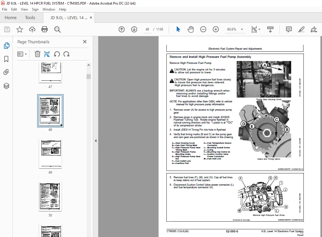
Remove and Install High Pressure Fuel Pump Assembly 48
Remove and Install Fuel Suction Control Valve 51
Remove and Install High Pressure Common Rail 54
Remove and Install Flow Dampers 56
Remove and Install Pressure Limiter 58
Remove and Install Leak-off Lines 59
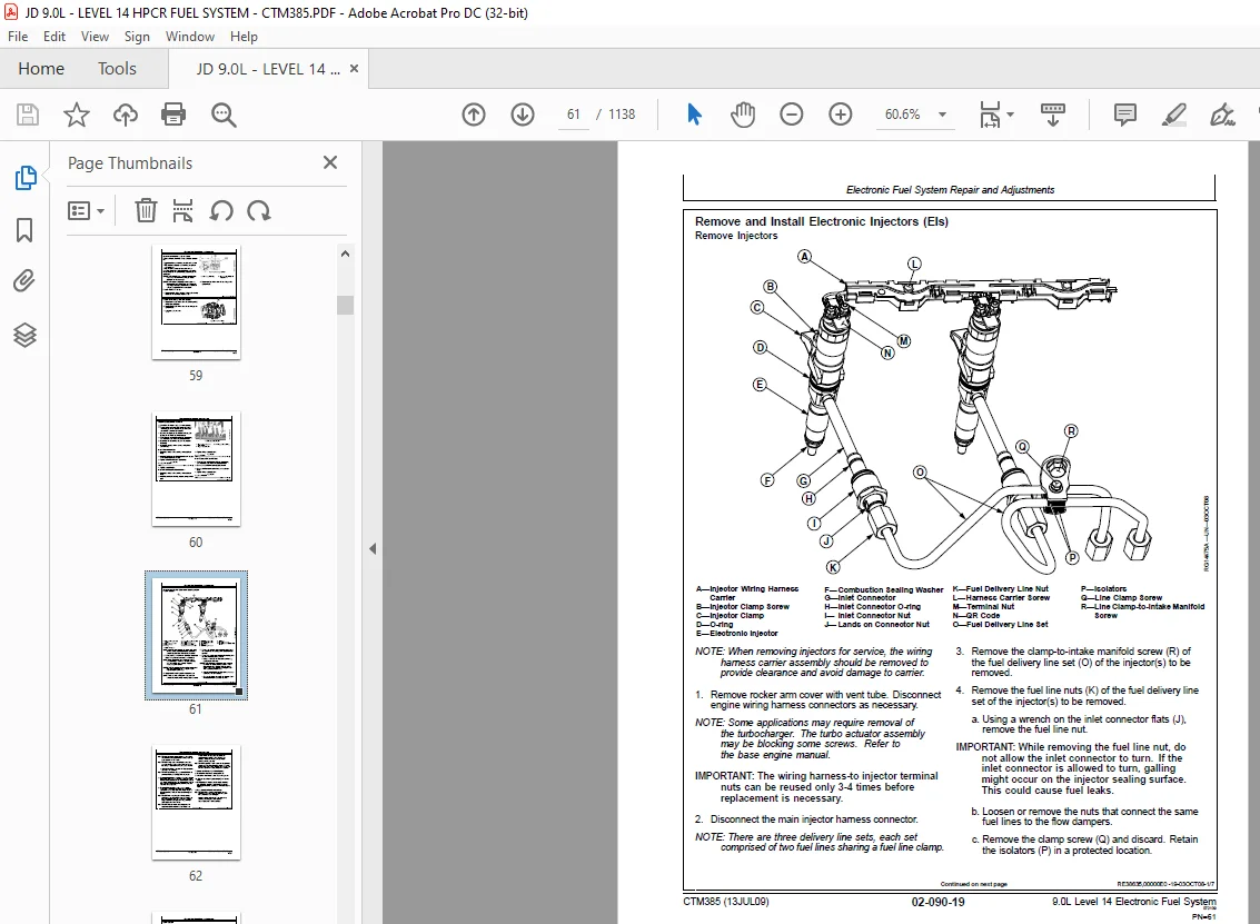
Remove and Install Electronic Injectors (EIs) 61
Remove and Install Fuel Injector Wiring Harness 66
Clean Electronic Injector (EI) Bore 70
Clean Electronic Injector (EI) Orifice 70
Clean Electronic Injector (EI) Body 70
Inspect Electronic Injector (EI) Body 70
Remove and Install Fuel Doser Header 71
Remove and Replace Doser Elements 75
Electronic Air System Repair and Adjustment 77
Remove & Install EGR Valve 77
Electronic Engine Control Repair and Adjustment 79
Fuel System – General Information 79
Remove and Install Coolant Temperature Sensor 79
Remove and Install Fuel Rail Pressure Sensor 79
Remove and Install High Pressure Pump (Camshaft Timing) Sensor 80
Remove and Install Oil Pressure Sensor 80
Remove and Install Water in Fuel (WIF) Sensor 80
Remove and Install Crankshaft Position Sensor 80
Remove and Install Turbo Speed Sensor 81
Remove and Install Manifold Air Pressure (MAP) Sensor 81
Remove and Install Manifold Air Temperature (MAT) Sensor 81
Remove and Install EGR Temperature Sensor 81
Remove and Install Charge Air Cooler Outlet Air Temperature Sens 82
Remove and Replace Air Intake Temperature – Turbocharger Compres 82
Engine Control Unit (ECU) Maintenance 83
Remove and Install Engine Control Unit (ECU) 84
Remove and Install Low Pressure Fuel Pressure Sensor 85
Remove and Install Air Bleed/Check Valve 86
Welding 86
High-Pressure Washing 87
Connectors 88
Connector Repair 89
Repair WEATHERPACK WEATHERPACK is a trademark of Packard Electri 90
Repair METRI-PACK Connector (Push Type) 92
Repair Cinch Flex Box Connector 94
Repair DT Series Deutsch Connectors 101
Repair HD Series Deutsch Connectors 105
ECU Wiring Harness Routing 108
Remove and Install Engine Wiring Harness 109
Theory Of Operation 115
Electronic Fuel System Operation 117
About This Group 117
Fuel System Operation 117
Fuel System Operation – Jet Fuel 118
Fuel Transfer Pump Operation 119
Primary Filter Operation 120
Doser Operation 121
Secondary Fuel Filter Operation 121
High Pressure Fuel Pump Operation 122
High Pressure Common Rail (HPCR) Operation 123
Electronic Injector (EI) Operation 124
Electronic Air System Operation 127
About This Group 127
Electronic Air System Control Operation 128
Exhaust Gas Recirculation Flow and Calculations 131
Turbocharger 131
Turbocharger Actuator 132
Exhaust Gas Recirculation Cooler 133
Exhaust Gas Recirculation Valve 133
Electronic Control System Operation 135
About This Group 135
Electronic Control System Terminology 136
Component Location Diagram 1 138
Component Location Diagram 2 140
Component Location Diagram 3 141
Component Location Diagram 4 142
Component Location Diagram 5 143
Component Location Diagram 6 144
Component Location Diagram 7 145
Component Location Diagram 8 146
Component Location Diagram 9 147
Engine Control Unit (ECU) System Operation 148
Controller Area Network (CAN) 150
Measuring Temperature 150
Engine Control Unit (ECU) Temperature Sensor 150
Engine Coolant Temperature (ECT) Sensor 150
Fuel Temperature Sensor 151
Exhaust Gas Recirculation (EGR) Exhaust Temperature Sensor 151
Charge Air Cooler Outlet Air Temperature Sensor 151
Intake Manifold Air Temperature (MAT) Sensor 152
Turbo Compressor Inlet Temperature Sensor 152
Turbo Turbine Inlet Temperature 152
Measuring Pressure 153
Barometric Air Pressure (BAP) Sensor 153
Fuel Rail Pressure Sensor 153
Fuel Transfer Pump Pressure Sensor 154
Manifold Air Pressure (MAP) Sensor 154
Oil Pressure Sensor 154
Dual Fuel Rail Pressure Sensor (Redundant ECU Applications) 155
Measuring Speed 156
Crank Position Sensor 156
Pump Position Sensor 156
Turbo Speed Sensor 156
Throttle Descriptions 157
CAN Throttle 157
Pulse-Width-Modulated (PWM) Throttle 158
Analog Throttle 158
Digital Multi-State Throttle 158
Dual-State Throttle 159
Tri-State Throttle 159
Ramp Throttle 160
Throttle Adjustments 161
Throttle Offsets 161
Self-Calibration 162
Combination Throttle 163
Marine Throttle 164
Engine Derate and Shutdown Protection 165
Electronic Injector (EI) Wiring Harness Connector 166
Intake Air Heater Operation 166
Torque Curve Selection 167
Governor Droop Mode Selection 167
Suction Control Valve 168
Water in Fuel (WIF) Sensor 168
Engine Coolant Level Switch 168
Cruise Control Operation 168
Power Supply #1 169
Power Supply #2 169
Power Supply #3 169
Power Supply #4 169
Power Supply #5 169
Diagnostics 179
Observable Diagnostics and Tests 181
About This Group 181
E1 – Engine Cranks/Won’t Start 182
E1 – Engine Cranks/Won’t Start Diagnostic Procedure 182
E2 – Engine Misfires/Runs Irregularly 187
E2 – Engine Misfires/Runs Irregularly Diagnostic Procedure 187
E3 – Engine Does Not Develop Full Power 191
E3 – Engine Does Not Develop Full Power Diagnostic Procedure 191
E4 – Engine Emits Excessive White Exhaust Smoke 197
E4 – Engine Emits Excessive White Exhaust Smoke Diagnostic Proce 197
E5 – Engine Emits Excessive Black or Gray Exhaust Smoke 200
E5 – Engine Emits Excessive Black or Gray Exhaust Smoke Diagnost 200
E6 – Engine Will Not Crank 204
E6 – Engine Will Not Crank Diagnostic Procedure 204
E7 – Engine Idles Poorly 207
E7 – Engine Idles Poorly Diagnostic Procedure 207
E8 – Abnormal Engine Noise 209
E9 – Primary Analog Throttle Does Not Respond 211
E9 – Primary Analog Throttle Does Not Respond 211
E10 – Secondary Analog Throttle Does Not Respond 213
E10 – Secondary Analog Throttle Does Not Respond 213
F1 – Low Pressure Fuel System Check 216
F1 – Low Pressure Fuel Supply System Test Diagnostic Procedure 216
F2 – High Pressure Fuel System Check 222
F2 – High Pressure Fuel Supply System Test Diagnostic Procedure 222
F3 – Excessive Fuel Consumption 231
F4 – Fuel in Oil 232
F4 – Fuel in Oil Diagnostic Procedure 232
F5 – Fuel in Coolant 234
F5 – Fuel in Coolant Diagnostic Procedure 234
D1 – ECU Does Not Communicate with Service ADVISOR 235
D1 – ECU Does Not Communicate with Service ADVISOR Diagnostic Pr 235
D2 – ECU Does Not Communicate with Diagnostic Gauge or Gauge Dis 242
D2 – ECU Does Not Communicate with Diagnostic Gauge or Gauge Dis 242
D3 – ECU Does Not Program With Service ADVISOR 246
D3 – ECU Does Not Program with Service ADVISOR Diagnostic Proced 246
A1 – Intake Air Heater Check 248
A1 – Intake Air Heater Check Diagnostic Procedure 248
Check Fuel Supply Quality 253
Check Fuel Supply Quality Diagnostic Procedure 253
Test The Fuel Bleed System 256
Test The Fuel Bleed System Diagnostic Procedure 256
Test for Air in Fuel 259
Bleed The Fuel System 261
Check for Restricted Fuel Leak-off Line 264
Check High Pressure Fuel Pump Static Timing 265
Excessive Engine Crankcase Pressure (Blow-By) 266
Excessive Engine Crankcase Pressure (Blow-By) Diagnostic Procedu 267
Charge Air System Diagnostic 270
Charge Air System Diagnostic 270
Variable Geometry Turbocharger (VGT) Component Test 272
Variable Geometry Turbocharger (VGT) Component Test Diagnostic P 272
Temperature Sensor Validity Test 276
Temperature Sensor Validity Test Diagnostic Procedure 276
EGR-VGT System Temperature and Flow Test 277
EGR-VGT System Temperature and Flow Test Procedure 277
Bleed Coolant System 280
Trouble Code Diagnostics and Tests 281
About This Group 281
Electrical Concepts 282
Using a Digital Multimeter 282
Electrical Circuit Malfunctions 282
Troubleshooting Circuit Malfunctions 284
Connecting to Service ADVISOR 287
Diagnostic Gauge Active DTC Viewing Instructions 293
Diagnostic Gauge Stored DTC Viewing Instructions 295
Diagnostic Gauge Stored DTC Clearing Instructions 297
Service ADVISOR Data Parameter Description 298
Snapshot Instructions 301
Terminal Test 302
Cylinder Misfire Test Instructions 308
Engine Test Instructions — Compression Test 309
Engine Test Instructions – Cylinder Cutout Test 312
Exhaust Gas Recirculation Valve Calibration 313
VGT Learn Value Reset Test 314
VGT Actuator Travel Range Test 316
Harness Diagnostic Mode Test 317
EGR Valve Clean Cycle 318
Fuel Rail Cap and Plug Kit 320
Engine Control Unit (ECU) Reprogramming Instructions 322
Trim Options Information 323
Payload File Downloading Instructions 324
Downloading Electronic Injector Calibration Files 325
Electronic Injector Calibration 326
Diagnostic Trouble Codes List 327
Diagnostic Trouble Code Designations 331
Failure Mode Indicator Designations 334
Intermittent DTC Diagnostics 336
Internal Data Monitor Instructions 337
Interactive Tests and Calibration Results Printing Instructions 338
Control Unit Information Gathering Interactive Test 339
Engine Hour Updating Instructions Using Service ADVISOR 339
00002803 — Digital Throttle Signal Out of Range High 339
00002803 — Throttle #3 Signal Out of Range High Diagnostic Proc 340
00002804 — Digital Throttle Signal Out of Range Low 345
00002804 — Digital Throttle Signal Out of Range Low Diagnostic 345
00002903 — Secondary Analog Throttle Signal Out of Range High 350
00002903 — Secondary Analog Throttle Signal Out of Range High D 350
00002904 — Secondary Analog Throttle Signal Out of Range Low 356
00002904 — Secondary Analog Throttle Signal Out of Range Low Di 356
00009103 — Primary Analog Throttle Signal Out of Range High 362
00009103 — Primary Analog Throttle Signal Out of Range High Dia 362
00009104 — Primary Analog Throttle Signal Out of Range Low 368
00009104 — Primary Analog Throttle Signal Out of Range Low Diag 368
00009403 — Low Pressure Fuel Signal Out of Range High 374
00009403 — Low Pressure Fuel Signal Out of Range High Diagnosti 374
00009404 — Low Pressure Fuel Signal Out of Range Low 379
00009404 — Low Pressure Fuel Signal Out of Range Low Diagnostic 379
00009417 — Low Pressure Fuel Signal Slightly Low 385
00009417 — Low Pressure Fuel Signal Slightly Low 385
00009703 — Water In Fuel Signal Out of Range High 388
00009703 — Water In Fuel Signal Out of Range High Diagnostic Pr 388
00009704 — Water In Fuel Signal Out of Range Low 393
00009704 — Water In Fuel Signal Out of Range Low 393
00009716 — Water in Fuel Detected 398
00009716 — Water In Fuel Detected Diagnostic Procedure 398
00010001 — Engine Oil Pressure Signal Extremely Low 402
00010001 — Engine Oil Pressure Signal Extremely Low Diagnostic 402
00010004 — Engine Oil Pressure Signal Out of Range Low 406
00010004 — Engine Oil Pressure Signal Out of Range Low Diagnost 406
00010018 — Engine Oil Pressure Signal Moderately Low 411
00010018 — Engine Oil Pressure Signal Moderately Low Diagnostic 411
00010031 — Engine Oil Pressure Detected with Engine Stopped 415
00010031 — Engine Oil Pressure Detected with Engine Stopped Dia 415
00010202 — Manifold Air Pressure Signal Invalid 419
00010202 — Manifold Air Pressure Signal Invalid 419
00010203 — Manifold Air Pressure Signal Out of Range High 422
00010203 — Manifold Air Pressure Signal Out of Range High 422
00010204 — Manifold Air Pressure Signal Out of Range Low 427
00010204 — Manifold Air Pressure Signal Out of Range Low Diagno 427
00010300 — Turbo Speed Extremely High 432
00010300 — Turbo Speed Extremely High Diagnostic Procedure 433
00010305 — Turbo Speed Signal Circuit has High Resistance 438
00010305 — Turbo Speed Signal Circuit Has High Resistance Diagn 438
00010308 — Turbo Speed Signal Incorrect 442
00010308 — Turbo Speed Signal Incorrect Diagnostic Procedure 442
00010331 — Turbo Speed Signal Missing 447
00010331 — Turbo Speed Signal Missing Diagnostic Procedure 447
00010500 — Manifold Air Temperature Signal Extremely High 452
00010500 — Manifold Air Temperature Signal Extremely High Diagn 453
00010503 — Manifold Air Temperature Signal Out of Range High 459
00010503 — Manifold Air Temperature Signal Out of Range High Di 459
00010504 — Manifold Air Temperature Signal Out of Range Low 464
00010504 — Manifold Air Temperature Signal Out of Range Low Dia 464
00010515 — Manifold Air Temperature Signal Slightly High 469
00010515 — Manifold Air Temperature Signal Slightly High Diagno 469
00010516 — Manifold Air Temperature Signal Moderately High 474
00010516 — Manifold Air Temperature Signal Moderately High Diag 474
00010700 — Air Filter Restriction Switch Activated 479
00010700 — Air Filter Restriction Switch Activated Diagnostic P 479
00010731 — Air Filter Restriction Switch Activated 480
00010731 — Air Filter Restriction Diagnostic Procedure 481
00010802 — Barometric Pressure Signal Invalid 486
00010802 — Barometric Pressure Signal Invalid Diagnostic Proced 486
00011000 — Coolant Temperature Signal Extremely High 488
00011000 — Coolant Temperature Signal Extremely High Diagnostic 489
00011003 — Coolant Temperature Signal Out of Range High 493
00011003 — Coolant Temperature Signal Out of Range High Diagnos 493
00011004 — Coolant Temperature Signal Out of Range Low 498
00011004 — Coolant Temperature Signal Out of Range Low Diagnost 498
00011015 — Coolant Temperature Signal Slightly High 503
00011015 — Coolant Temperature Signal Slightly High Diagnostic 503
00011016 — Coolant Temperature Signal Moderately High 507
00011016 — Coolant Temperature Signal Moderately High Diagnosti 507
00011017 — Coolant Temperature Signal Slightly Low 511
00011017 — Coolant Temperature Signal Slightly Low Diagnostic P 511
00011101 — Coolant Level Extremely Low 515
00011101 — Coolant Level Extremely Low Diagnostic Procedure 515
00015703 — Fuel Rail Pressure Signal Out of Range High 520
00015703 — Fuel Rail Pressure Signal Out of Range High Diagnost 520
00015704 — Fuel Rail Pressure Signal Out of Range Low 527
00015704 — Fuel Rail Pressure Signal Out of Range Low Diagnosti 527
00015710 — Fuel Rail Pressure Loss Detected 533
00015710 — Fuel Rail Pressure Loss Detected Diagnostic Procedur 534
00015717 — Fuel Rail Pressure Not Developed 538
00015717 — Fuel Rail Pressure Not Developed Diagnostic Procedur 538
00015817 — ECU Power Down Error 541
00015817 — ECU Power Down Error Diagnostic Procedure 541
00017400 — Fuel Temperature Signal Extremely High 543
00017400 — Fuel Temperature Signal Extremely High Diagnostic Pr 544
00017403 — Fuel Temperature Signal Out of Range High 548
00017403 — Fuel Temperature Signal Out of Range High Diagnostic 548
00017404 — Fuel Temperature Signal Out of Range Low 553
00017404 — Fuel Temperature Signal Out of Range Low Diagnostic 553
00017416 — Fuel Temperature Signal Moderately High 558
00017416 — Fuel Temperature Signal Moderately High Diagnostic P 558
00018900 — Engine Speed Derate Condition Exists 562
00019000 — Engine Speed Extremely High 563
00019000 — Engine Speed Extremely High Diagnostic Procedure 563
00019016 — Engine Speed Moderately High 566
00019016 — Engine Speed Moderately High Diagnostic Procedure 566
00023702 — VIN Security Data Invalid 569
00023713 — VIN Option Code Security Data Conflict 570
00023731 — VIN Security Data Missing 571
00041200 — EGR Temperature Signal Extremely High 572
00041200 — EGR Temperature Signal Extremely High Diagnostic Pro 572
00041203 — EGR Temperature Signal Out of Range High 577
00041203 —EGR Temperature Signal Out of Range High Diagnostic P 577
00041204 — EGR Temperature Signal Out of Range Low 582
00041204 — EGR Temperature Signal Out of Range Low Diagnostic P 582
00041215 — EGR Temperature Signal Slightly High 587
0041215 — EGR Temperature Signal Slighty High Diagnostic Proced 587
00041216 — EGR Temperature Signal Moderately High 592
0041216 — EGR Temperature Signal Moderately High Diagnostic Pro 592
00061103 — Injector Shorted to Voltage Source 597
00061103 — Injector Shorted to Voltage Source Diagnostic Proced 597
00061104 — Injector Shorted to Ground 602
00061104 — Injector Shorted to Ground Diagnostic Procedure 602
00062701 — All Injector Circuits Have High Resistance 608
00062701— All Injector Circuits Have High Resistance Diagnostic 608
00062718 — Injector Power Supply Voltage Moderately Low 613
00062718 — Injector Power Supply Voltage Moderately Low 613
00062912 — ECU EEPROM Error 616
00062912 — ECU EEPROM Error Diagnostic Procedure 617
00062913 — ECU Boot Block Error 618
00062913 — ECU Boot Block Error Diagnostic Procedure 618
00063602 — Camshaft Position Signal Invalid 619
00063602 — Camshaft Position Signal Invalid 619
00063605 — Camshaft Position Circuit Circuit Has High Resistanc 624
00063605 — Camshaft Position Circuit Has High Resistance Diagno 624
00063606 — Camshaft Position Circuit Has Low Resistance 627
00063606 — Camshaft Position Circuit Has Low Resistance Diagnos 627
00063608 — Camshaft Position Signal Missing 631
00063608 — Camshaft Position Signal Missing 631
00063610 — Camshaft Position Signal Rate of Change Abnormal 636
00063610 — Camshaft Position Signal Rate of Change Abnormal 636
00063702 — Crankshaft Position Signal Invalid 642
00063702 — Crankshaft Position Signal Invalid 642
00063705 — Crank Sensor Circuit Has High Resistance 647
00063705 — Crank Sensor Circuit Has High Resistance Diagnostic 647
00063706 — Crankshaft Position Circuit Has Low Resistance 650
00063706 — Crankshaft Position Circuit Has Low Resistance Diagn 650
00063707 — Crankshaft and Camshaft Position Signals Out of Sync 654
00063707 — Crankshaft and Camshaft Position Signals Out of Sync 654
00063708 — Crankshaft Position Signal Missing 659
00063708 — Crankshaft Position Signal Missing Diagnostic Proced 659
00063710 — Crankshaft Position Signal Rate of Change Abnormal 663
00063710 — Crankshaft Position Signal Rate of Change Abnormal D 663
00064011 — External Engine Protection Commanded 669
00064031 — External Derate Commanded 670
00064104 — VGT Actuator Supply Voltage Out of Range Low 671
00064104 — VGT Actuator Supply Voltage Out of Range Low Diagnos 671
00064112 — VGT Actuator Communication Error 676
00064112 — VGT Actuator Communication Error Diagnostic Procedur 676
00064113 — VGT Actuator Learn Error 681
00064113 — VGT Actuator Learn Error Diagnostic Procedure 681
00064116 — VGT Actuator Temperature Moderately High 684
00064116 — VGT Actuator Temperature Moderately High Diagnostic 684
00064705 — Engine Fan Drive Circuit Has High Resistance 687
00064707 — Engine Fan Drive Not Responding 688
00064731 — Engine Fan Drive Manual Purge Switch Active Too Long 689
00065102 — Injector #1 Part # Data Invalid 690
00065102 — Injector #1 Part Number Invalid Diagnostic Procedure 690
00065105 — Injector #1 Circuit Has High Resistance 693
00065105 — Injector #1 Circuit Has High Resistance Diagnostic P 693
00065106 — Injector #1 Circuit Has Low Resistance 697
00065106 — Injector #1 Circuit Has Low Resistance Diagnostic Pr 697
00065107 — Injector #1 Not Responding 702
00065107 — Injector #1 Not Responding Diagnostic Procedure 702
00065113 — Injector #1 Calibration Fault 706
00065113 — Injector #1 Calibration Fault Diagnostic Procedure 706
00065202 — Injector #2 Part # Data Invalid 708
00065202 — Injector #2 Part Number Invalid Diagnostic Procedure 708
00065205 — Injector #2 Circuit Has High Resistance 711
00065205 — Injector #2 Circuit Has High Resistance Diagnostic P 711
00065206 — Injector #2 Circuit Has Low Resistance 715
00065206 — Injector #2 Circuit Has Low Resistance Diagnostic Pr 715
00065207 — Injector #2 Not Responding 720
00065207 — Injector #2 Not Responding Diagnostic Procedure 720
00065213 — Injector #2 Calibration Fault 724
00065213 — Injector #2 Calibration Fault Diagnostic Procedure 724
00065302 — Injector #3 Part # Data Invalid 726
00065302 — Injector #3 Part Number Invalid Diagnostic Procedure 726
00065305 — Injector #3 Circuit Has High Resistance 729
00065305 — Injector #3 Circuit Has High Resistance Diagnostic P 729
00065306 — Injector #3 Circuit Has Low Resistance 733
00065306 — Injector #3 Circuit Has Low Resistance Diagnostic Pr 733
00065307 — Injector #3 Not Responding 738
00065307 — Injector #3 Not Responding Diagnostic Procedure 738
00065313 — Injector #3 Calibration Fault 742
00065313 — Injector #3 Calibration Fault Diagnostic Procedure 742
00065402 — Injector #4 Part # Data Invalid 744
00065402 — Injector #4 Part Number Invalid Diagnostic Procedure 744
00065405 — Injector #4 Circuit Has High Resistance 747
00065405 — Injector #4 Circuit Has High Resistance Diagnostic P 747
00065406 — Injector #4 Circuit Has Low Resistance 751
00065406 — Injector #4 Circuit Has Low Resistance Diagnostic Pr 751
00065407 — Injector #4 Not Responding 756
00065407 — Injector #4 Not Responding Diagnostic Procedure 756
00065413 — Injector #4 Calibration Fault 760
00065413 — Injector #4 Calibration Fault Diagnostic Procedure 760
00065502 — Injector #5 Part # Data Invalid 762
00065502 — Injector #5 Part Number Invalid Diagnostic Procedure 762
00065505 — Injector #5 Circuit Has High Resistance 765
00065505 — Injector #5 Circuit Has High Resistance Diagnostic P 765
00065506 — Injector #5 Circuit Has Low Resistance 769
00065506 — Injector #5 Circuit Has Low Resistance Diagnostic Pr 769
00065507 — Injector #5 Not Responding 774
00065507 — Injector #5 Not Responding Diagnostic Procedure 774
00065513 — Injector #5 Calibration Fault 778
00065513 — Injector #5 Calibration Fault Diagnostic Procedure 778
00065602 — Injector #6 Part # Data Invalid 780
00065602 — Injector #6 Part Number Invalid Diagnostic Procedure 780
00065605 — Injector #6 Circuit Has High Resistance 783
00065605 — Injector #6 Circuit Has High Resistance Diagnostic P 783
00065606 — Injector #6 Circuit Has Low Resistance 787
00065606 — Injector #6 Circuit Has Low Resistance Diagnostic Pr 787
00065607 — Injector #6 Not Responding 792
00065607 — Injector #6 Not Responding Diagnostic Procedure 792
00065613 — Injector #6 Calibration Fault 796
00065613 — Injector #6 Calibration Fault Diagnostic Procedure 796
00089809 — Engine Speed CAN Message Invalid 798
00097031 — External Shutdown Switch Activated 799
00097031 — External Shutdown Commanded Diagnostic Procedure 799
00097131 — External Derate Switch Activated 804
00097131 — External Derate Switch Activated Diagnostic Procedur 804
00107512 — Low Pressure Fuel Pump Status Error 809
00107512 — Low Pressure Fuel Pump Status Error Diagnostic Proce 809
00110931 — Approaching Engine Protection Shutdown 814
00110931 — Approaching Engine Protection Shutdown Diagnostic Pr 814
00111031 — Engine Protection Shutdown Active 815
00111031 — Engine Protection Shutdown Active Diagnostic Procedu 815
00113600 — ECU Temperature Signal Extremely High 816
00113600 — ECU Temperature Signal Extremely High Diagnostic Pro 816
00113616 — ECU Temperature Signal Moderately High 819
00113616 — ECU Temperature Signal Moderately High Diagnostic Pr 819
00117203 — Turbo Compressor Inlet Temperature Signal Out of Ran 822
00117203 — Turbo Compressor Inlet Temperature Signal Out of Ran 822
00117204 — Turbo Compressor Inlet Temperature Signal Out of Ran 827
00117204 — Turbo Compressor Inlet Temperature Signal Out of Ran 827
00118000 — Calculated Turbo Turbine Inlet Temperature Signal Ex 832
00118000 — Calculated Turbine Inlet Temperature Signal Extremel 833
00118016 — Turbine Inlet Temperature Signal Moderately High 840
00118016 — Calculated Turbine Inlet Temperature Signal Moderate 841
00134703 — Suction Control Valve Signal Out of Range High 848
00134703 — Suction Control Valve Signal Out of Range High Diagn 848
00134705 — Suction Control Valve Circuit Has High Resistance 852
00134705 — Suction Control Valve Circuit Has High Resistance Di 852
00134707 — Fuel Rail Pressure Actual to Desired Mismatch 856
00134707 — Fuel Rail Pressure Actual to Desired Mismatch Diagno 857
00134902 — Fuel Rail Pressure Signals Mismatch 859
00134902 — Fuel Rail Pressure Signals Mismatch Diagnostic Proce 860
00134903 — Redundant Fuel Rail Pressure Signal Out of Range Hig 865
00134903 — Redundant Fuel Rail Pressure Signal Out of Range Hig 866
00134904 — Redundant Fuel Rail Pressure Signal Out of Range Low 870
00134904 — Redundant Fuel Rail Pressure Signal Out of Range Low 871
00156802 — Torque Curve Selection Error 876
00156802—Torque Curve Selection Error Diagnostic Procedure 876
00156931 — Engine in Power Derate Condition 877
00163800 — Hydraulic Oil Temperature Signal Extremely High 878
00163803 — Hydraulic Oil Temperature Signal Out of Range High 879
00163804 — Hydraulic Oil Temperature Signal Out of Range Low 880
00163809 — Hydraulic Oil Temperature Signal Erratic 881
00163816 — Hydraulic Oil Temperature Signal Moderately High 882
00163901 — Fan Speed Signal Extremely Low 883
00163916 — Fan Speed Signal Moderately High 884
00163918 — Fan Speed Signal Moderately Low 885
00200013 — Incorrect ECU for Application 886
00200409 — No CAN Message From Source Address 4 887
00200509 — No CAN Message From Source Address 5 888
00200514 — Incorrect CAN Message Received From Source Address 5 889
00200514 — Incorrect ACU Message Received Diagnostic Procedure 889
00203009 — No CAN Message From Source Address 30 890
00207109 — No CAN Message From Source Address 71 891
00263000 — Charge Air Cooler Outlet Temperature Signal Extremel 892
00263000 – Charge Air Cooler Outlet Temperature Signal Extremel 892
00263003 — Charge Air Cooler Outlet Temperature Signal Out Of R 897
00263003 — Charge Air Cooler Outlet Temperature Signal Out of R 897
00263004 — Charge Air Cooler Outlet Temperature Signal Out of R 902
00263004 — Charge Air Cooler Outlet Temperature Signal Out of R 902
00263015 — Charge Air Cooler Outlet Temperature Signal Slightly 907
00263015 — Charge Air Cooler Outlet Temperature Signal Slightly 907
00263016 — Charge Air Cooler Outlet Temperature Signal Moderate 912
00263016 — Charge Air Cooler Outlet Temperature Signal Moderate 912
00265902 — Calculated EGR Flow Rate Invalid 917
00265902 — Calculated EGR Flow Rate Invalid Diagnostic Procedur 918
00265915 — Calculated EGR Flow Rate Slightly High 926
00265915 — Calculated EGR Flow Rate Slightly High Diagnostic Pr 927
00265917 — Calculated EGR Flow Rate Slightly Low 934
00265917 — Calculated EGR Flow Rate Slightly Low Diagnostic Pro 935
00279016 — Calculated Compressor Outlet Temperature Moderately 943
00279016 — Calculated Compressor Outlet Temperature Moderately 944
00279102 — EGR Valve Position Signal Invalid 950
00279102 – EGR Valve Position Signal Invalid Diagnostic Procedu 951
00279103 — EGR Valve Position Signal Out of Range High 956
00279103 — EGR Valve Position Signal Out of Range High Diagnost 957
00279104 — EGR Valve Position Signal Out of Range Low 965
00279104 — EGR Valve Position Signal Out of Range Low Diagnosti 966
00279107 — EGR Valve Not Reaching Expected Position 971
00279107 – EGR Valve Not Reaching Expected Position Diagnostic 971
00279113 — EGR Valve Calibration Change Over a Short Period of 977
00279113 — EGR Valve Calibration Change Over a Short Period of 978
00279131 — EGR Valve Calibration Change Over a Long Time 983
00279131 — EGR Valve Calibration Change over a Long Time Diagno 984
00279507 — VGT Actuator Not Reaching Expected Position 989
00279507 — VGT Actuator Not Reaching Expected Position Diagnost 989
00350903 — Sensor Supply #1 Voltage Out of Range High 992
00350903 — Sensor Supply #1 Voltage Out of Range High Diagnosti 992
00350904 — Sensor Supply #1 Voltage Out of Range Low 995
00350904 — Sensor Supply #1 Voltage Out of Range Low Diagnostic 995
00351003 — Sensor Supply #2 Voltage Out of Range High 999
00351003 — Sensor Supply #2 Voltage Out of Range High Diagnosti 999
00351004 — Sensor Supply #2 Voltage Out of Range Low1002
00351004 — Sensor Supply #2 Voltage Out of Range Low Diagnostic1002
00351103 — Sensor Supply #3 Voltage Out of Range High1006
00351103 — Sensor Supply #3 Voltage Out of Range High Diagnosti1006
00351104 — Sensor Supply #3 Voltage Out of Range Low1010
00351104 — Sensor Supply #3 Voltage Out of Range Low Diagnostic1010
00351203 — Sensor Supply #4 Voltage Out of Range High1014
00351203 — Sensor Supply #4 Voltage Out of Range High Diagnosti1014
00351204 — Sensor Supply #4 Voltage Out of Range Low1018
00351204 — Sensor Supply #4 Voltage Out of Range Low Diagnostic1018
00351303 — Sensor Supply #5 Voltage Out of Range High1022
00351303 — Sensor Supply #5 Voltage Out of Range High Diagnosti1022
00351304 — Sensor Supply #5 Voltage Out of Range Low1025
00351304 — Sensor Supply #5 Voltage Out of Range Low Diagnostic1025
00358705 — Ether Hold Control Circuit Has High Resistance1028
00358706 — Ether Hold Control Circuit Has Low Resistance1028
52337903 — Single Point Ground #7 Has High Resistance1029
52374431 — A/C Compressor is ON When it Should be OFF1030
52392603 — Reverse Pump Pressure Sensor #1 Signal Out Of Range 1031
52392604 — Reverse Pump Pressure Sensor #1 Signal Out Of Rang1032
52392703 — Forward Pump Pressure Sensor #2 Signal Out Of Range 1033
52392704 — Forward Pump Pressure Sensor #2 Signal Out Of Range 1034
Tools1035
Electronic Fuel/Control System Repair Tools and Other Materials1037
Repair and Adjustment Tools1037
Electronic Fuel System Diagnostic Tools1039
Connector Repair Tools1040
Other Material1043
Diagnostic Service Tools1045
Diagnostic Tools1045
Dealer Fabricated Service Tools1049
How to make tools1049
DFRG9 – Monometer1049
Specifications1051
Repair Specifications1053
Unified Inch Bolt and Cap Screw Torque Values1053
Metric Bolt and Cap Screw Torque Values1054
Electronic Air System Repair and Adjustment Specifications1055
Electronic Fuel System Repair and Adjustment Specifications 1056
Electronic Engine Control Repair and Adjustment Specifications1057
Diagnostic Specifications1059
Application Specifications1059
OEM Engines – Derate Specifications1060
OEM Engines – Air Heater Specifications1061
EGR Temperature Sensor Characteristics 1062
Compressor Inlet Air Temperature Sensor Characteristics1063
Manifold Air Temperature Sensor and Charged Air Cooler Outlet Te1064
90L 12V Wiring Diagram 11066
90L 12V Wiring Diagram 21068
90L 12V Wiring Diagram 31070
90L 12V Wiring Diagram 41072
90L 12V Wiring Diagram 51074
90L 12V Wiring Diagram 61076
90L 12V Wiring Diagram 71078
90L 12V Wiring Diagram 81080
90L 24V Wiring Diagram 11082
90L 24V Wiring Diagram 21084
90L 24V Wiring Diagram 31086
90L 24V Wiring Diagram 41088
90L 24V Wiring Diagram 51090
90L 24V Wiring Diagram 61092
90L 24V Wiring Diagram 71094
90L 24V Wiring Diagram 81096
OEM Instrument Panel / Engine Start Components Electrical Wiring1099
OEM Instrument Panel / Engine Start Components Electrical Wiring1105
90L Wire Splice Location Diagrams1106
Oil Temperature Switch Option1116
Redundant ECU Option 90L Wiring Diagrams1117
Redundant ECU Option 90L Wiring Splice Location Diagrams1124
Page Number 3
Section 01 5
Group 000 7
Group 001 21
Group 002 29
Section 02 41
Group 090 43
Group 100 77
Group 110 79
Section 03 115
Group 130 117
Group 135 127
Group 140 135
Section 04 179
Group 150 181
Group 160 281
Section 051035
Group 1701037
Group 1801045
Group 1901049
Section 061051
Group 2001053
Group 2101059
S.M 8/1/25