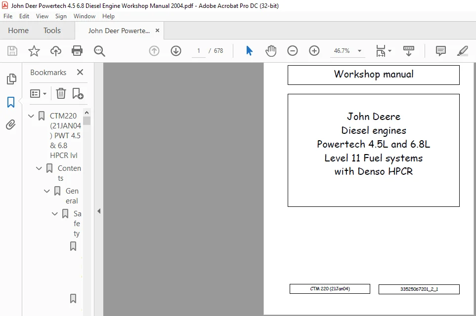
John Deere Diesel engines Powertech 4.5L & 6.8L Level 11 Fuel systems with Denso HPCR Workshop Manual
Original price was: $89.95.$29.95Current price is: $29.95.
John Deere Diesel engines Powertech 4.5L & 6.8L Level 11 Fuel systems with Denso HPCR Workshop Manual – PDF DOWNLOAD
Description
John Deere Diesel engines Powertech 4.5L & 6.8L Level 11 Fuel systems with Denso HPCR Workshop Manual – PDF DOWNLOAD
DESCRIPTION:
John Deere Diesel engines Powertech 4.5L & 6.8L Level 11 Fuel systems with Denso HPCR Workshop Manual – PDF DOWNLOAD
For complete service information also see:
POWERTECHâ 4.5 L and 6.8 L Diesel
Engines—Base Engine . . . . . . . . . . . . . . . . . CTM104
Alternators and Starter Motors. . . . . . . . . . . CTM77
OEM Engine Accessories . . . . . . CTM67 (English Only)
Forward :
- This manual is written for an experienced technician. Essential tools required in performing certain service work are identified in this manual and are recommended for use.
- This manual (CTM220) covers only Level 11 Electronic Fuel System with the Denso High Pressure Common Rail (HPCR). It is one of six volumes on 4.5 L and 6.8 L engines. The following five companion manuals cover the base engine, mechanical fuel system, and other electronic control systems. Each manual covers repair, operation, and diagnostics.
· CTM104—Base Engine
· CTM170—Level 4 Electronic Fuel System with
Bosch VP44 Pump
· CTM207—Mechanical Fuel Systems
· CTM284—Level 1 Electronic Fuel System with
Delphi (Lucas) DP201 Pump
· CTM331—Level 12 Electronic Fuel System with
Stanadyne DE 10 Pump
- Other manuals will be added in the future to provide additional information on electronic fuel systems as needed.
- A complete set of all these manuals covering 4.5 L and 6.8 L engines is available in a binder by ordering CTM 350 Binder Set.
- Live with safety: Read the safety messages in the introduction of this manual and the cautions presented throughout the text of the manual.
TABLE OF CONTENTS:
John Deere Diesel engines Powertech 4.5L & 6.8L Level 11 Fuel systems with Denso HPCR Workshop Manual – PDF DOWNLOAD
CTM220 (21JAN04) PWT 4.5 & 6.8 HPCR lvl 11 (GB).pdf……………………………………………………. 0
Contents………………………………………………………………………………………. 5
General……………………………………………………………………………………. 7
Safety…………………………………………………………………………………. 9
Handle Fluids Safely—Avoid Fires………………………………………………………. 9
Handle Starting Fluid Safely………………………………………………………….. 9
Service Cooling System Safely…………………………………………………………. 9
Prevent Battery Explosions……………………………………………………………. 10
Prepare for Emergencies………………………………………………………………. 10
Handling Batteries Safely…………………………………………………………….. 11
Avoid High-Pressure Fluids……………………………………………………………. 12
Wear Protective Clothing……………………………………………………………… 12
Service Machines Safely………………………………………………………………. 13
Work In Ventilated Area………………………………………………………………. 13
Work in Clean Area…………………………………………………………………… 13
Remove Paint Before Welding or Heating…………………………………………………. 14
Avoid Heating Near Pressurized Fluid Lines……………………………………………… 14
Illuminate Work Area Safely…………………………………………………………… 14
Use Proper Lifting Equipment………………………………………………………….. 15
Construct Dealer-Made Tools Safely…………………………………………………….. 15
Practice Safe Maintenance…………………………………………………………….. 16
Use Proper Tools…………………………………………………………………….. 16
Dispose of Waste Properly…………………………………………………………….. 17
Live With Safety…………………………………………………………………….. 17
Engine Identification……………………………………………………………………. 19
Engine Model Designation……………………………………………………………… 19
Engine Serial Number Plate Information…………………………………………………. 20
OEM Engine Option Code Label………………………………………………………….. 21
Information Relative to Emissions Regulations…………………………………………… 21
Engine Application Charts…………………………………………………………….. 22
Fuels, Lubricants, and Coolant……………………………………………………………. 23
Lubricants and Coolant……………………………………………………………….. 23
Diesel Fuel…………………………………………………………………………. 23
Bio-Diesel Fuel……………………………………………………………………… 24
Dieselscan Fuel Analysis……………………………………………………………… 24
Lubricity of Diesel Fuel……………………………………………………………… 25
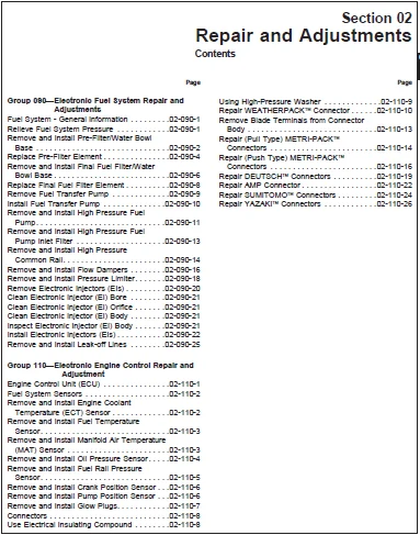
Repair and Adjustments………………………………………………………………………. 27
Electronic Fuel System Repair and Adjustments………………………………………………. 29
Fuel System – General Information……………………………………………………… 29
Relieve Fuel System Pressure………………………………………………………….. 29
Remove and Install Pre-Filter/Water Bowl Base…………………………………………… 30
Replace Pre-Filter Element……………………………………………………………. 32
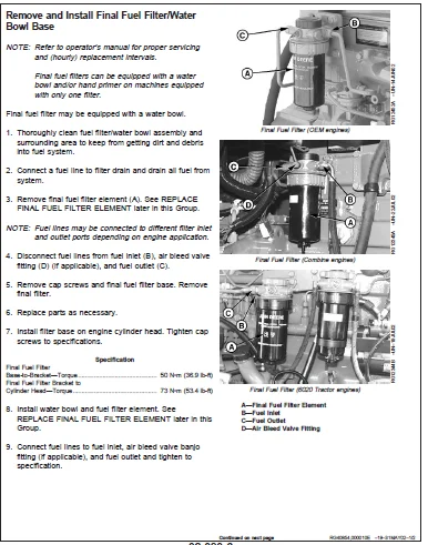
Remove and Install Final Fuel Filter/Water Bowl Base…………………………………….. 34
Replace Final Fuel Filter Element……………………………………………………… 36
Remove Fuel Transfer Pump…………………………………………………………….. 37
Install Fuel Transfer Pump……………………………………………………………. 38
Remove and Install High Pressure Fuel Pump……………………………………………… 39
Remove and Install High Pressure Fuel Pump Inlet Filter………………………………….. 41
Remove and Install High Pressure Common Rail……………………………………………. 42
Remove and Install Flow Dampers……………………………………………………….. 44
Remove and Install Pressure Limiter……………………………………………………. 46
Remove Electronic Injectors (EIs)……………………………………………………… 48
Clean Electronic Injector (EI) Bore……………………………………………………. 49
Clean Electronic Injector (EI) Orifice…………………………………………………. 49
Clean Electronic Injector (EI) Body……………………………………………………. 49
Inspect Electronic Injector (EI) Body………………………………………………….. 49
Install Electronic Injectors (EIs)…………………………………………………….. 50
Remove and Install Leak-off Lines……………………………………………………… 53
Electronic Engine Control Repair and Adjustment…………………………………………….. 55
Engine Control Unit (ECU)…………………………………………………………….. 55
Fuel System Sensors………………………………………………………………….. 56
Remove and Install Engine Coolant Temperature (ECT) Sensor……………………………….. 56
Remove and Install Fuel Temperature Sensor……………………………………………… 57
Remove and Install Manifold Air Temperature (MAT) Sensor…………………………………. 57
Remove and Install Oil Pressure Sensor…………………………………………………. 58
Remove and Install Fuel Rail Pressure Sensor……………………………………………. 59
Remove and Install Crank Position Sensor……………………………………………….. 60
Remove and Install Pump Position Sensor………………………………………………… 60
Remove and Install Glow Plugs…………………………………………………………. 61
Connectors………………………………………………………………………….. 62
Use Electrical Insulating Compound…………………………………………………….. 62
Using High-Pressure Washer……………………………………………………………. 63
Repair WEATHERPACK™ Connector…………………………………………………………. 64
Remove Blade Terminals from Connector Body……………………………………………… 67
Repair (Pull Type) METRI-PACK™ Connectors………………………………………………. 68
Repair (Push Type) METRI-PACK™ Connectors………………………………………………. 70
Repair DEUTSCH™ Connectors……………………………………………………………. 73
Repair AMP Connector…………………………………………………………………. 76
Repair SUMITOMO™ Connectors…………………………………………………………… 78
Repair YAZAKI™ Connectors…………………………………………………………….. 80
Theory Of Operation…………………………………………………………………………. 83
Electronic Fuel System Operation………………………………………………………….. 85
About This Group…………………………………………………………………….. 85
Fuel System Operation………………………………………………………………… 86
Pre-filter Operation…………………………………………………………………. 87
Fuel Transfer Pump Operation………………………………………………………….. 88
Final Fuel Filter Operation…………………………………………………………… 89
High Pressure Fuel Pump Operation……………………………………………………… 90
High Pressure Common Rail (HPCR) Operation……………………………………………… 91
Electronic Injector (EI) Operation…………………………………………………….. 92
Electronic Control System Operation……………………………………………………….. 95
About This Group…………………………………………………………………….. 95
Electronic Control System Terminology………………………………………………….. 96
Electronic Control System Operation……………………………………………………. 97
Electronic Control System Overview…………………………………………………….. 98
Monitoring Engine Parameters………………………………………………………….. 99
Measuring Temperature………………………………………………………………… 99
Measuring Pressure……………………………………………………………………102
Measuring Throttle Position……………………………………………………………104
Measuring Engine Speed………………………………………………………………..107
Pump Control Valve (PCV)………………………………………………………………108
Water in Fuel (WIF) Sensor…………………………………………………………….108
Electronic Injector (EI) Wiring Harness Connector………………………………………..109
Engine Control Unit (ECU)……………………………………………………………..110
Controlled Area Network (CAN)………………………………………………………….112
Glow Plug Operation…………………………………………………………………..112
Cruise Control Operation………………………………………………………………113
Engine Protection…………………………………………………………………….114
Derate Programs………………………………………………………………………114
Multiple Torque Curve Selection………………………………………………………..115
Governor Droop Mode Selection………………………………………………………….115
Engine Control Unit (ECU) Self-Diagnosis………………………………………………..116
Diagnostics…………………………………………………………………………………119
Observable Diagnostics and Tests…………………………………………………………..125
About This Group……………………………………………………………………..125
E1 – Engine Cranks/Won’t Start…………………………………………………………126
E1 – Engine Cranks/Won’t Start Diagnostic Procedure………………………………………126
……………………………………………………………………………………126
……………………………………………………………………………………126
……………………………………………………………………………………127
……………………………………………………………………………………127
……………………………………………………………………………………127
……………………………………………………………………………………128
……………………………………………………………………………………128
……………………………………………………………………………………128
E2 – Engine Misfires/Runs Irregularly…………………………………………………..129
E2 – Engine Misfires/Runs Irregularly Diagnostic Procedure………………………………..129
……………………………………………………………………………………129
……………………………………………………………………………………129
……………………………………………………………………………………129
……………………………………………………………………………………130
……………………………………………………………………………………130
……………………………………………………………………………………131
……………………………………………………………………………………131
……………………………………………………………………………………131
……………………………………………………………………………………132
……………………………………………………………………………………132
……………………………………………………………………………………132
……………………………………………………………………………………132
E3 – Engine Does Not Develop Full Power…………………………………………………133
E3 – Engine Does Not Develop Full Power Diagnostic Procedure………………………………133
……………………………………………………………………………………133
……………………………………………………………………………………133
……………………………………………………………………………………134
……………………………………………………………………………………134
……………………………………………………………………………………135
……………………………………………………………………………………135
……………………………………………………………………………………135
……………………………………………………………………………………136
……………………………………………………………………………………136
……………………………………………………………………………………136
……………………………………………………………………………………137
……………………………………………………………………………………137
……………………………………………………………………………………137
E4 – Engine Emits Excessive White Exhaust Smoke………………………………………….138
E4 – Engine Emits Excessive White Exhaust Smoke Diagnostic Procedure……………………….138
……………………………………………………………………………………138
……………………………………………………………………………………138
……………………………………………………………………………………139
……………………………………………………………………………………139
……………………………………………………………………………………139
……………………………………………………………………………………140
E5 – Engine Emits Excessive Black Or Gray Exhaust Smoke…………………………………..141
E5 – Engine Emits Excessive Black Or Gray Exhaust Smoke Diagnostic Procedure………………..141
……………………………………………………………………………………141
……………………………………………………………………………………141
……………………………………………………………………………………141
……………………………………………………………………………………142
……………………………………………………………………………………142
……………………………………………………………………………………142
E6 – Engine Will Not Crank…………………………………………………………….143
E7 – Engine Idles Poorly………………………………………………………………143
E8 – Abnormal Engine Noise…………………………………………………………….144
E9 – Analog Throttle (A) Does Not Respond……………………………………………….146
E10 – Analog Throttle (B) Does Not Respond………………………………………………146
F1 – Fuel Supply System Check………………………………………………………….148
F1 – Fuel Supply System Check Diagnostic Procedure……………………………………….148
……………………………………………………………………………………148
……………………………………………………………………………………148
……………………………………………………………………………………148
……………………………………………………………………………………149
……………………………………………………………………………………149
……………………………………………………………………………………149
……………………………………………………………………………………150
……………………………………………………………………………………150
……………………………………………………………………………………150
……………………………………………………………………………………150
……………………………………………………………………………………151
……………………………………………………………………………………151
……………………………………………………………………………………151
……………………………………………………………………………………152
……………………………………………………………………………………152
F2 – Excessive Fuel Consumption………………………………………………………..153
F3 – Fuel in Oil……………………………………………………………………..153
D1 – ECU Does Not Communicate with DST or SERVICE ADVISOR™………………………………..154
…………………………………………………………………………………..155
D1 – ECU Does Not Communicate With DST or SERVICE ADVISOR™ Diagnostic Procedure……………..155
……………………………………………………………………………………155
……………………………………………………………………………………155
……………………………………………………………………………………156
……………………………………………………………………………………156
……………………………………………………………………………………156
……………………………………………………………………………………156
……………………………………………………………………………………157
……………………………………………………………………………………157
……………………………………………………………………………………157
……………………………………………………………………………………158
D2 – Diagnostic Gauge Does Not Communicate With ECU………………………………………160
…………………………………………………………………………………..161
D2 – Diagnostic Gauge Does Not Communicate With ECU Diagnostic Procedure……………………161
……………………………………………………………………………………161
……………………………………………………………………………………161
……………………………………………………………………………………162
……………………………………………………………………………………162
……………………………………………………………………………………162
……………………………………………………………………………………162
……………………………………………………………………………………163
……………………………………………………………………………………163
……………………………………………………………………………………163
……………………………………………………………………………………164
A2 – Glow Plug Check………………………………………………………………….166
A2 – Glow Plug Check………………………………………………………………….167
A2 – Glow Plug Check………………………………………………………………….168
A2 – Glow Plug Check Diagnostic Procedure……………………………………………….168
……………………………………………………………………………………168
……………………………………………………………………………………168
……………………………………………………………………………………169
……………………………………………………………………………………169
……………………………………………………………………………………169
……………………………………………………………………………………169
……………………………………………………………………………………170
……………………………………………………………………………………170
Check Fuel Supply Quality……………………………………………………………..171
Test for Air in Fuel………………………………………………………………….173
Check Fuel Supply Pressure…………………………………………………………….174
Check for Restricted Fuel Leak-off Line…………………………………………………175
Bleed the Fuel System…………………………………………………………………177
Check and Adjust High Pressure Fuel Pump Static Timing……………………………………180
Trouble Code Diagnostics and Tests…………………………………………………………181
About This Group……………………………………………………………………..181
Electrical Concepts…………………………………………………………………..182
Using a Digital Multimeter…………………………………………………………….182
Electrical Circuit Malfunctions………………………………………………………..183
Troubleshooting Circuit Malfunctions……………………………………………………186
Connecting to Diagnostic Scan Tool (DST) or SERVICE ADVISOR™………………………………190
Blinking DTCs………………………………………………………………………..192
Engine Configuration Data Parameters on Diagnostic Gauge………………………………….193
Viewing Active DTCs on Diagnostic Gauge…………………………………………………195
Viewing Stored DTCs on Diagnostic Gauge…………………………………………………195
Clearing Stored DTCs on Diagnostic Gauge………………………………………………..196
Data Parameter Description…………………………………………………………….198
Engine Test Instructions—Cylinder Misfire Test…………………………………………..202
Engine Test Instructions—Compression Test……………………………………………….203
Engine Test Instructions— Cylinder Cutout Test…………………………………………..204
Engine Test Instructions— Tractor Torque Curve Change Test………………………………..205
Reprogramming Engine Control Unit (ECU)…………………………………………………206
Downloading Payload File For DST……………………………………………………….207
Reprogramming Engine Control Unit (ECU) With DST…………………………………………212
Downloading Payload File For SERVICE ADVISOR™……………………………………………217
Reprogramming Engine Control Unit (ECU) With SERVICE ADVISOR™……………………………..225
Diagnostic Trouble Codes (DTCs)………………………………………………………..229
Listing of Diagnostic Trouble Codes (DTCs) on ECU………………………………………..230
Diagnostic Procedure………………………………………………………………….234
Intermittent Fault Diagnostics…………………………………………………………235
T1 – Multi-state Throttle Input High……………………………………………………236
…………………………………………………………………………………..237
T1 – Multi-State Throttle Input High Diagnostic Procedure…………………………………237
……………………………………………………………………………………237
……………………………………………………………………………………237
……………………………………………………………………………………238
……………………………………………………………………………………238
T2 – Multi-state Throttle Input Low…………………………………………………….240
…………………………………………………………………………………..241
T2 – Multi-State Throttle Input Low Diagnostic Procedure………………………………….241
……………………………………………………………………………………241
……………………………………………………………………………………241
……………………………………………………………………………………242
T3 – Analog Throttle (A) Input High…………………………………………………….244
…………………………………………………………………………………..245
T3 – Analog Throttle (A) Input High Diagnostic Procedure………………………………….245
……………………………………………………………………………………245
……………………………………………………………………………………245
……………………………………………………………………………………246
……………………………………………………………………………………246
……………………………………………………………………………………246
T4 – Analog Throttle (A) Input Low……………………………………………………..248
…………………………………………………………………………………..249
T4 – Analog Throttle (A) Input Low Diagnostic Procedure…………………………………..249
……………………………………………………………………………………249
……………………………………………………………………………………249
……………………………………………………………………………………250
……………………………………………………………………………………250
……………………………………………………………………………………251
T5 – Analog Throttle (B) Input High…………………………………………………….252
…………………………………………………………………………………..253
T5 – Analog Throttle (B) Input High Diagnostic Procedure………………………………….253
……………………………………………………………………………………253
……………………………………………………………………………………253
……………………………………………………………………………………254
……………………………………………………………………………………254
……………………………………………………………………………………254
T6 – Analog Throttle (B) Input Low……………………………………………………..256
…………………………………………………………………………………..257
T6 – Analog Throttle (B) Input Low Diagnostic Procedure…………………………………..257
……………………………………………………………………………………257
……………………………………………………………………………………257
……………………………………………………………………………………258
……………………………………………………………………………………258
……………………………………………………………………………………259
T7 – CAN Throttle Invalid……………………………………………………………..260
…………………………………………………………………………………..261
T7 – CAN Throttle Invalid Diagnostic Procedure…………………………………………..261
……………………………………………………………………………………261
……………………………………………………………………………………261
……………………………………………………………………………………262
……………………………………………………………………………………262
……………………………………………………………………………………262
T17 – Analog Throttle (C) Input High……………………………………………………264
…………………………………………………………………………………..265
T17 – Analog Throttle (C) Input High Diagnostic Procedure…………………………………265
……………………………………………………………………………………265
……………………………………………………………………………………265
……………………………………………………………………………………266
……………………………………………………………………………………266
……………………………………………………………………………………266
T18 – Analog Throttle (C) Input Low…………………………………………………….268
…………………………………………………………………………………..269
T18 – Analog Throttle (C) Input Low Diagnostic Procedure………………………………….269
……………………………………………………………………………………269
……………………………………………………………………………………269
……………………………………………………………………………………270
……………………………………………………………………………………270
……………………………………………………………………………………270
T22 – Analog Throttle (A) Input Voltage Out of Range……………………………………..271
000028.03 — Throttle Voltage High………………………………………………………272
000028.04 — Throttle Voltage Low……………………………………………………….272
000029.03 — Throttle Voltage High………………………………………………………273
000029.04 — Throttle Voltage Low……………………………………………………….273
000084.31 — Vehicle Speed Mismatch……………………………………………………..274
…………………………………………………………………………………..275
000084.31 Vehicle Speed Mismatch Diagnostic Procedure…………………………………….275
……………………………………………………………………………………275
……………………………………………………………………………………275
……………………………………………………………………………………275
……………………………………………………………………………………276
……………………………………………………………………………………276
……………………………………………………………………………………276
000091.03 — Throttle Voltage High………………………………………………………277
000091.04 — Throttle Voltage Low……………………………………………………….278
000091.09 — Throttle Invalid…………………………………………………………..278
000091.14 — Throttle Voltage Out of Range……………………………………………….279
000094.03 — Fuel Rail Pressure Input Voltage High………………………………………..280
…………………………………………………………………………………..281
000094.03 Fuel Rail Pressure Input Voltage High Diagnostic Procedure……………………….281
……………………………………………………………………………………281
……………………………………………………………………………………281
……………………………………………………………………………………282
……………………………………………………………………………………282
000094.04 Fuel Rail Pressure Input Voltage Low…………………………………………..284
…………………………………………………………………………………..285
000094.04 Fuel Rail Pressure Input Voltage Low Diagnostic Procedure………………………..285
……………………………………………………………………………………285
……………………………………………………………………………………285
……………………………………………………………………………………286
……………………………………………………………………………………286
000094.10 — Fuel Rail Pressure Loss Detected…………………………………………….288
…………………………………………………………………………………..289
000094.10 Fuel Rail Pressure Loss Detected Diagnostic Procedure……………………………289
……………………………………………………………………………………289
……………………………………………………………………………………289
……………………………………………………………………………………290
……………………………………………………………………………………290
000094.13 — Fuel Rail Pressure Higher Than Expected………………………………………292
…………………………………………………………………………………..293
000094.13 Fuel Rail Pressure Higher Than Expected Diagnostic Procedure……………………..293
……………………………………………………………………………………293
……………………………………………………………………………………293
……………………………………………………………………………………294
……………………………………………………………………………………294
000094.17 — Fuel Rail Pressure Not Developed…………………………………………….296
…………………………………………………………………………………..297
000094.17 Fuel Rail Pressure Not Developed Diagnostic Procedure……………………………297
……………………………………………………………………………………297
……………………………………………………………………………………297
……………………………………………………………………………………298
……………………………………………………………………………………298
……………………………………………………………………………………298
……………………………………………………………………………………298
……………………………………………………………………………………299
000097.00 — Water in Fuel Continuously Detected………………………………………….300
…………………………………………………………………………………..301
000097.00 Water In Fuel Continuously Detected Diagnostic Procedure…………………………301
……………………………………………………………………………………301
……………………………………………………………………………………301
……………………………………………………………………………………302
……………………………………………………………………………………302
000097.03 — Water in Fuel Signal Voltage High……………………………………………303
…………………………………………………………………………………..304
000097.03 Water in Fuel Signal Voltage High Diagnostic Procedure…………………………..304
……………………………………………………………………………………304
……………………………………………………………………………………304
……………………………………………………………………………………305
……………………………………………………………………………………305
000097.04 — Water in Fuel Signal Voltage Low…………………………………………….306
…………………………………………………………………………………..307
000097.04 Water in Fuel Signal Voltage Low Diagnostic Procedure……………………………307
……………………………………………………………………………………307
……………………………………………………………………………………307
……………………………………………………………………………………308
000097.16 — Water in Fuel Detected……………………………………………………..310
…………………………………………………………………………………..311
000097.16 Water In Fuel Detected Diagnostic Procedure…………………………………….311
……………………………………………………………………………………311
……………………………………………………………………………………311
……………………………………………………………………………………312
……………………………………………………………………………………312
000100.01 — Engine Oil Pressure Extremely Low……………………………………………314
…………………………………………………………………………………..316
000100.01 Engine Oil Pressure Extremely Low Diagnostic Procedure…………………………..316
……………………………………………………………………………………316
……………………………………………………………………………………316
000100.03 — Engine Oil Pressure Input Voltage High……………………………………….318
…………………………………………………………………………………..319
000100.03 Engine Oil Pressure Input Voltage High Diagnostic Procedure………………………319
……………………………………………………………………………………319
……………………………………………………………………………………319
……………………………………………………………………………………320
……………………………………………………………………………………320
000100.04 — Engine Oil Pressure Input Voltage Low………………………………………..322
…………………………………………………………………………………..324
000100.04 Oil Pressure Input Voltage Low Diagnostic Procedure……………………………..324
……………………………………………………………………………………324
……………………………………………………………………………………324
……………………………………………………………………………………325
……………………………………………………………………………………325
……………………………………………………………………………………325
……………………………………………………………………………………326
000100.18 — Engine Oil Pressure Moderately Low…………………………………………..328
…………………………………………………………………………………..329
000100.18 Engine Oil Pressure Moderately Low Diagnostic Procedure………………………….329
……………………………………………………………………………………329
……………………………………………………………………………………329
000105.00 — Manifold Air Temperature Extremely High………………………………………330
…………………………………………………………………………………..331
000105.00 Manifold Air Temperature Extremely High Diagnostic Procedure……………………..331
……………………………………………………………………………………331
……………………………………………………………………………………331
000105.03 — Manifold Air Temperature Input Voltage High…………………………………..332
…………………………………………………………………………………..333
000105.03 Manifold Air Temperature Input Voltage High Diagnostic Procedure………………….333
……………………………………………………………………………………333
……………………………………………………………………………………333
……………………………………………………………………………………334
……………………………………………………………………………………334
000105.04 — Manifold Air Temperature Input Voltage Low……………………………………336
…………………………………………………………………………………..337
000105.04 Manifold Air Temperature Input Voltage Low Diagnostic Procedure…………………..337
……………………………………………………………………………………337
……………………………………………………………………………………337
……………………………………………………………………………………338
000105.16 — Manifold Air Temperature Moderately High……………………………………..340
…………………………………………………………………………………..341
000105.16 Manifold Air Temperature Moderately High Diagnostic Procedure…………………….341
……………………………………………………………………………………341
……………………………………………………………………………………341
000107.00 — Air Filter Differential Pressure…………………………………………….342
…………………………………………………………………………………..343
000107.00 Air Filter Differential Pressure Diagnostic Procedure……………………………343
……………………………………………………………………………………343
……………………………………………………………………………………343
……………………………………………………………………………………344
……………………………………………………………………………………344
000110.00 — Engine Coolant Temperature Extremely High…………………………………….346
…………………………………………………………………………………..347
000110.00 Engine Coolant Temperature Extremely High Diagnostic Procedure……………………347
……………………………………………………………………………………347
……………………………………………………………………………………347
000110.03 — Engine Coolant Temperature Input Voltage High…………………………………348
…………………………………………………………………………………..349
000110.03 Engine Coolant Temperature Input Voltage High Diagnostic Procedure………………..349
……………………………………………………………………………………349
……………………………………………………………………………………349
……………………………………………………………………………………350
……………………………………………………………………………………350
000110.04 — Engine Coolant Temperature Input Voltage Low………………………………….352
…………………………………………………………………………………..353
000110.04 Engine Coolant Temperature Input Voltage Low Diagnostic Procedure…………………353
……………………………………………………………………………………353
……………………………………………………………………………………353
……………………………………………………………………………………354
000110.15 — Engine Coolant Temperature High Least Severe………………………………….356
…………………………………………………………………………………..357
000110.15 Engine Coolant Temperature High Least Severe Diagnostic Procedure…………………357
……………………………………………………………………………………357
……………………………………………………………………………………357
000110.16 — Engine Coolant Temperature Moderately High……………………………………358
…………………………………………………………………………………..359
000110.16 Engine Coolant Temperature Moderately High Diagnostic Procedure…………………..359
……………………………………………………………………………………359
……………………………………………………………………………………359
000111.01 — Engine Coolant Level Low……………………………………………………360
…………………………………………………………………………………..361
000111.01 Engine Coolant Level Low Diagnostic Procedure…………………………………..361
……………………………………………………………………………………361
……………………………………………………………………………………361
……………………………………………………………………………………362
……………………………………………………………………………………362
000158.17 — ECU Power Down Error……………………………………………………….364
…………………………………………………………………………………..365
000158.17 ECU Power Down Error Diagnostic Procedure………………………………………365
……………………………………………………………………………………365
……………………………………………………………………………………365
……………………………………………………………………………………366
000160.02 — Wheel Speed Input Noise…………………………………………………….368
…………………………………………………………………………………..369
000160.02 Wheel Speed Input Noise Diagnostic Procedure……………………………………369
……………………………………………………………………………………369
……………………………………………………………………………………369
……………………………………………………………………………………370
……………………………………………………………………………………370
……………………………………………………………………………………370
000174.00 — Fuel Temperature High Most Severe……………………………………………372
…………………………………………………………………………………..373
000174.00 Fuel Temperature High Most Severe Diagnostic Procedure…………………………..373
……………………………………………………………………………………373
……………………………………………………………………………………373
……………………………………………………………………………………373
……………………………………………………………………………………374
000174.03 — Fuel Temperature Input Voltage High………………………………………….376
…………………………………………………………………………………..377
000174.03 Fuel Temperature Input Voltage High Diagnostic Procedure…………………………377
……………………………………………………………………………………377
……………………………………………………………………………………377
……………………………………………………………………………………378
……………………………………………………………………………………378
000174.04 — Fuel Temperature Input Voltage Low…………………………………………..380
…………………………………………………………………………………..381
000174.04 Fuel Temperature Input Voltage Low Diagnostic Procedure………………………….381
……………………………………………………………………………………381
……………………………………………………………………………………381
……………………………………………………………………………………382
000174.16 — Fuel Temperature High Moderately Severe………………………………………384
…………………………………………………………………………………..385
000174.16 Fuel Temperature High Moderately Severe Diagnostic Procedure……………………..385
……………………………………………………………………………………385
……………………………………………………………………………………385
……………………………………………………………………………………385
……………………………………………………………………………………386
000189.00 — Engine Speed Derate………………………………………………………..387
000190.00 — Engine Overspeed Extreme……………………………………………………388
000190.16 — Engine Overspeed Moderate…………………………………………………..389
000237.02 — Vehicle Identification Number Invalid………………………………………..390
000237.13 — Vehicle Identification Option Code Invalid……………………………………391
000237.31 — Vehicle Model Number Invalid………………………………………………..392
000611.03 — Electronic Injector Wiring Shorted To Power Source…………………………….394
…………………………………………………………………………………..396
000611.03 Electronic Injector Wiring Shorted To Power Source Diagnostic Procedure……………396
……………………………………………………………………………………396
……………………………………………………………………………………396
……………………………………………………………………………………397
……………………………………………………………………………………397
……………………………………………………………………………………397
000611.04 — Electronic Injector Wiring Shorted To Ground………………………………….398
…………………………………………………………………………………..400
000611.04 Electronic Injector Wiring Shorted To Ground Diagnostic Procedure…………………400
……………………………………………………………………………………400
……………………………………………………………………………………400
……………………………………………………………………………………401
……………………………………………………………………………………401
……………………………………………………………………………………401
……………………………………………………………………………………402
……………………………………………………………………………………402
000620.03 — Sensor Supply 2 Voltage High………………………………………………..404
…………………………………………………………………………………..405
000620.03 Sensor Supply 2 Voltage High Diagnostic Procedure……………………………….405
……………………………………………………………………………………405
……………………………………………………………………………………405
……………………………………………………………………………………406
000620.04 — Sensor Supply 2 Voltage Low…………………………………………………408
…………………………………………………………………………………..409
000620.04 Sensor Supply 2 Voltage Low Diagnostic Procedure………………………………..409
……………………………………………………………………………………409
……………………………………………………………………………………409
……………………………………………………………………………………410
……………………………………………………………………………………410
000627.01 — Electronic Injector Supply Voltage Problem……………………………………412
…………………………………………………………………………………..413
000627.01 Electronic Injector Supply Voltage Problem Diagnostic Procedure…………………..413
……………………………………………………………………………………413
……………………………………………………………………………………413
……………………………………………………………………………………414
……………………………………………………………………………………414
000629.13 — ECU Error…………………………………………………………………416
000629.13 ECU Error Diagnostic Procedure………………………………………………..416
……………………………………………………………………………………416
000636.02 — Pump Position Sensor Input Noise…………………………………………….418
…………………………………………………………………………………..419
000636.02 Pump Position Sensor Input Noise Diagnostic Procedure……………………………419
……………………………………………………………………………………419
……………………………………………………………………………………419
……………………………………………………………………………………420
000636.08 — Pump Position Sensor Input Missing…………………………………………..422
…………………………………………………………………………………..423
000636.08 Pump Position Sensor Input Missing Diagnostic Procedure………………………….423
……………………………………………………………………………………423
……………………………………………………………………………………423
……………………………………………………………………………………424
……………………………………………………………………………………424
……………………………………………………………………………………424
……………………………………………………………………………………425
000636.10 — Pump Position Sensor Input Pattern Error……………………………………..426
…………………………………………………………………………………..427
000636.10 Pump Position Sensor Input Pattern Error Diagnostic Procedure…………………….427
……………………………………………………………………………………427
……………………………………………………………………………………427
……………………………………………………………………………………428
……………………………………………………………………………………428
……………………………………………………………………………………428
……………………………………………………………………………………429
000637.02 — Crank Position Input Noise………………………………………………….430
…………………………………………………………………………………..431
000637.02 Crank Position Input Noise Diagnostic Procedure…………………………………431
……………………………………………………………………………………431
……………………………………………………………………………………431
……………………………………………………………………………………432
000637.07 — Crank Position/Pump Position Timing Moderately Out of Sync……………………..434
…………………………………………………………………………………..436
000637.07 Crank Position/Pump Position Timing Moderately Out of Sync Diagnostic Procedure…….436
……………………………………………………………………………………436
……………………………………………………………………………………436
……………………………………………………………………………………437
……………………………………………………………………………………437
……………………………………………………………………………………437
……………………………………………………………………………………437
……………………………………………………………………………………438
……………………………………………………………………………………438
……………………………………………………………………………………438
……………………………………………………………………………………439
……………………………………………………………………………………439
……………………………………………………………………………………439
000637.08 — Crank Position Input Missing………………………………………………..440
…………………………………………………………………………………..441
000637.08 Crank Position Input Missing Diagnostic Procedure……………………………….441
……………………………………………………………………………………441
……………………………………………………………………………………441
……………………………………………………………………………………442
……………………………………………………………………………………442
……………………………………………………………………………………442
……………………………………………………………………………………443
……………………………………………………………………………………443
000637.10 — Crank Position Input Pattern Error…………………………………………..444
…………………………………………………………………………………..445
000637.10 Crank Position Input Pattern Error Diagnostic Procedure………………………….445
……………………………………………………………………………………445
……………………………………………………………………………………445
……………………………………………………………………………………446
……………………………………………………………………………………446
……………………………………………………………………………………446
……………………………………………………………………………………447
……………………………………………………………………………………447
……………………………………………………………………………………447
000639.13 — CAN Bus Error……………………………………………………………..448
…………………………………………………………………………………..449
000639.13 CAN Bus Error Diagnostic Procedure…………………………………………….449
……………………………………………………………………………………449
……………………………………………………………………………………449
……………………………………………………………………………………450
……………………………………………………………………………………450
000651.05 — Cylinder #1 EI Circuit Open…………………………………………………452
…………………………………………………………………………………..454
000651.05 Cylinder #1 EI Circuit Open Diagnostic Procedure………………………………..454
……………………………………………………………………………………454
……………………………………………………………………………………454
……………………………………………………………………………………455
……………………………………………………………………………………455
……………………………………………………………………………………456
000651.06 — Cylinder #1 EI Circuit Shorted………………………………………………458
…………………………………………………………………………………..460
000651.06 Cylinder #1 EI Circuit Shorted Diagnostic Procedure……………………………..460
……………………………………………………………………………………460
……………………………………………………………………………………460
……………………………………………………………………………………461
……………………………………………………………………………………461
……………………………………………………………………………………461
000651.07 — Cylinder #1 EI Mechanical Failure……………………………………………462
…………………………………………………………………………………..464
000651.07 Cylinder #1 EI Mechanical Failure Diagnostic Procedure…………………………..464
……………………………………………………………………………………464
……………………………………………………………………………………464
……………………………………………………………………………………465
……………………………………………………………………………………465
……………………………………………………………………………………465
000652.05 — Cylinder #2 EI Circuit Open…………………………………………………466
…………………………………………………………………………………..468
000652.05 Cylinder #2 EI Circuit Open Diagnostic Procedure………………………………..468
……………………………………………………………………………………468
……………………………………………………………………………………468
……………………………………………………………………………………469
……………………………………………………………………………………469
……………………………………………………………………………………469
……………………………………………………………………………………470
……………………………………………………………………………………470
000652.06 — Cylinder #2 EI Circuit Shorted………………………………………………472
…………………………………………………………………………………..474
000652.06 Cylinder #2 EI Circuit Shorted Diagnostic Procedure……………………………..474
……………………………………………………………………………………474
……………………………………………………………………………………474
……………………………………………………………………………………475
……………………………………………………………………………………475
……………………………………………………………………………………475
……………………………………………………………………………………476
……………………………………………………………………………………476
000652.07 — Cylinder #2 EI Mechanical Failure……………………………………………478
…………………………………………………………………………………..480
000652.07 Cylinder #2 EI Mechanical Failure Diagnostic Procedure…………………………..480
……………………………………………………………………………………480
……………………………………………………………………………………480
……………………………………………………………………………………481
……………………………………………………………………………………481
……………………………………………………………………………………481
000653.05 — Cylinder #3 EI Circuit Open…………………………………………………482
…………………………………………………………………………………..484
000653.05 Cylinder #3 EI Circuit Open Diagnostic Procedure………………………………..484
……………………………………………………………………………………484
……………………………………………………………………………………484
……………………………………………………………………………………485
……………………………………………………………………………………485
……………………………………………………………………………………485
……………………………………………………………………………………486
……………………………………………………………………………………486
000653.06 — Cylinder #3 EI Circuit Shorted………………………………………………488
…………………………………………………………………………………..490
000653.06 Cylinder #3 EI Circuit Shorted Diagnostic Procedure……………………………..490
……………………………………………………………………………………490
……………………………………………………………………………………490
……………………………………………………………………………………491
……………………………………………………………………………………491
……………………………………………………………………………………491
……………………………………………………………………………………492
……………………………………………………………………………………492
000653.07 — Cylinder #3 EI Mechanical Failure……………………………………………494
…………………………………………………………………………………..496
000653.07 Cylinder #3 EI Mechanical Failure Diagnostic Procedure…………………………..496
……………………………………………………………………………………496
……………………………………………………………………………………496
……………………………………………………………………………………497
……………………………………………………………………………………497
……………………………………………………………………………………497
000654.05 — Cylinder #4 EI Circuit Open…………………………………………………498
…………………………………………………………………………………..500
000654.05 Cylinder #4 EI Circuit Open Diagnostic Procedure………………………………..500
……………………………………………………………………………………500
……………………………………………………………………………………500
……………………………………………………………………………………500
……………………………………………………………………………………501
……………………………………………………………………………………501
……………………………………………………………………………………502
……………………………………………………………………………………502
000654.06 — Cylinder #4 EI Circuit Shorted………………………………………………504
…………………………………………………………………………………..506
000654.06 Cylinder #4 EI Circuit Shorted Diagnostic Procedure……………………………..506
……………………………………………………………………………………506
……………………………………………………………………………………506
……………………………………………………………………………………507
……………………………………………………………………………………507
……………………………………………………………………………………507
……………………………………………………………………………………508
……………………………………………………………………………………508
000654.07 — Cylinder #4 EI Mechanical Failure……………………………………………510
…………………………………………………………………………………..512
000654.07 Cylinder #4 EI Mechanical Failure Diagnostic Procedure…………………………..512
……………………………………………………………………………………512
……………………………………………………………………………………512
……………………………………………………………………………………513
……………………………………………………………………………………513
……………………………………………………………………………………513
000655.05 — Cylinder #5 EI Circuit Open…………………………………………………514
…………………………………………………………………………………..515
000655.05 Cylinder #5 EI Circuit Open Diagnostic Procedure………………………………..515
……………………………………………………………………………………515
……………………………………………………………………………………515
……………………………………………………………………………………516
……………………………………………………………………………………516
……………………………………………………………………………………517
000655.06 — Cylinder #5 EI Circuit Shorted………………………………………………518
…………………………………………………………………………………..519
000655.06 Cylinder #5 EI Circuit Shorted Diagnostic Procedure……………………………..519
……………………………………………………………………………………519
……………………………………………………………………………………519
……………………………………………………………………………………520
……………………………………………………………………………………520
……………………………………………………………………………………520
000655.07 — Cylinder #5 EI Mechanical Failure……………………………………………522
…………………………………………………………………………………..523
000655.07 Cylinder #5 EI Mechanical Failure Diagnostic Procedure…………………………..523
……………………………………………………………………………………523
……………………………………………………………………………………523
……………………………………………………………………………………524
……………………………………………………………………………………524
……………………………………………………………………………………524
000656.05 — Cylinder #6 EI Circuit Open…………………………………………………526
…………………………………………………………………………………..527
000656.05 Cylinder #6 EI Circuit Open Diagnostic Procedure………………………………..527
……………………………………………………………………………………527
……………………………………………………………………………………527
……………………………………………………………………………………528
……………………………………………………………………………………528
……………………………………………………………………………………529
000656.06 — Cylinder #6 EI Circuit Shorted………………………………………………530
…………………………………………………………………………………..531
000656.06 Cylinder #6 EI Circuit Shorted Diagnostic Procedure……………………………..531
……………………………………………………………………………………531
……………………………………………………………………………………531
……………………………………………………………………………………532
……………………………………………………………………………………532
……………………………………………………………………………………532
000656.07 — Cylinder #6 EI Mechanical Failure……………………………………………534
…………………………………………………………………………………..535
000656.07 Cylinder #6 EI Mechanical Failure Diagnostic Procedure…………………………..535
……………………………………………………………………………………535
……………………………………………………………………………………535
……………………………………………………………………………………536
……………………………………………………………………………………536
……………………………………………………………………………………536
000676.03 — Glow Plug Relay Voltage High………………………………………………..538
…………………………………………………………………………………..539
000676.03 Glow Plug Relay Voltage High Diagnostic Procedure……………………………….539
……………………………………………………………………………………539
……………………………………………………………………………………539
……………………………………………………………………………………540
……………………………………………………………………………………540
000676.05 — Glow Plug Relay Voltage Low…………………………………………………542
…………………………………………………………………………………..543
000676.05 Glow Plug Relay Voltage Low Diagnostic Procedure………………………………..543
……………………………………………………………………………………543
……………………………………………………………………………………543
……………………………………………………………………………………544
……………………………………………………………………………………544
……………………………………………………………………………………544
000898.09 — Vehicle Speed or Torque Message Invalid………………………………………545
000970.31 — Engine Shutdown – Auxiliary Request………………………………………….546
000971.31 — External Fuel Derate Switch Active…………………………………………..547
001069.09 — Tire Size Invalid………………………………………………………….548
001069.09 — Tire Size Invalid………………………………………………………….549
001069.09 Tire Size Invalid Diagnostic Procedure…………………………………………549
……………………………………………………………………………………549
……………………………………………………………………………………549
……………………………………………………………………………………550
……………………………………………………………………………………550
……………………………………………………………………………………550
001069.31 — Tire Size Error……………………………………………………………552
…………………………………………………………………………………..553
001069.31 Tire Size Error Diagnostic Procedure…………………………………………..553
……………………………………………………………………………………553
……………………………………………………………………………………553
001079.03 — Sensor Supply 1 Voltage High………………………………………………..554
…………………………………………………………………………………..555
001079.03 Sensor Supply 1 Voltage High Diagnostic Procedure……………………………….555
……………………………………………………………………………………555
……………………………………………………………………………………555
……………………………………………………………………………………556
001079.04 — Sensor Supply 1 Voltage Low…………………………………………………558
…………………………………………………………………………………..559
001079.04 Sensor Supply 1 Voltage Low Diagnostic Procedure………………………………..559
……………………………………………………………………………………559
……………………………………………………………………………………559
……………………………………………………………………………………560
……………………………………………………………………………………560
001080.03 — Fuel Rail Pressure Sensor Supply Voltage High…………………………………562
…………………………………………………………………………………..563
001080.03 Fuel Rail Pressure Sensor Supply Voltage High Diagnostic Procedure……………….563
……………………………………………………………………………………563
……………………………………………………………………………………563
……………………………………………………………………………………564
001080.04 — Fuel Rail Pressure Sensor Supply Voltage Low………………………………….566
…………………………………………………………………………………..567
001080.04 Fuel Rail Pressure Sensor Supply Voltage Low Diagnostic Procedure…………………567
……………………………………………………………………………………567
……………………………………………………………………………………567
……………………………………………………………………………………568
……………………………………………………………………………………568
001109.31 — Engine Protection Shutdown Warning…………………………………………..570
001110.31 — Engine Protection Shutdown………………………………………………….571
001347.03 — Pump Control Valve Current High……………………………………………..572
…………………………………………………………………………………..573
001347.03 Pump Control Valve Current High Diagnostic Procedure…………………………….573
……………………………………………………………………………………573
……………………………………………………………………………………573
……………………………………………………………………………………574
……………………………………………………………………………………574
001347.05 — Pump Control Valve Current Mismatch………………………………………….576
…………………………………………………………………………………..577
001347.05 Pump Control Valve Current Mismatch Diagnostic Procedure…………………………577
……………………………………………………………………………………577
……………………………………………………………………………………577
……………………………………………………………………………………578
……………………………………………………………………………………578
001347.07 — Fuel Rail Pressure Control Error…………………………………………….580
…………………………………………………………………………………..581
001347.07 Fuel Rail Pressure Control Error Diagnostic Procedure……………………………581
……………………………………………………………………………………581
……………………………………………………………………………………581
……………………………………………………………………………………582
……………………………………………………………………………………582
001347.10 — Pump Control Valve Fuel Flow Not Detected…………………………………….584
001347.10 — Pump Control Valve Fuel Flow Not Detected…………………………………….585
001347.10 Pump Control Valve Fuel Flow Not Detected DIagnostic Procedure……………………585
……………………………………………………………………………………585
……………………………………………………………………………………585
……………………………………………………………………………………586
001568.02 — Torque Curve Selection Invalid………………………………………………588
001569.31 — Fuel Derate……………………………………………………………….589
001639.01 — Fan Speed Input Missing…………………………………………………….590
…………………………………………………………………………………..591
001639.01 Fan Speed Input Missing Diagnostic Procedure……………………………………591
……………………………………………………………………………………591
……………………………………………………………………………………591
……………………………………………………………………………………592
……………………………………………………………………………………592
……………………………………………………………………………………592
……………………………………………………………………………………593
001639.16 — Fan Speed Higher Than Expected………………………………………………594
…………………………………………………………………………………..595
001639.16 Fan Speed Higher Than Expected Diagnostic Procedure……………………………..595
……………………………………………………………………………………595
……………………………………………………………………………………595
……………………………………………………………………………………596
……………………………………………………………………………………596
001639.18 — Fan Speed Lower Than Expected……………………………………………….598
…………………………………………………………………………………..599
001639.18 Fan Speed Lower Than Expected Diagnostic Procedure………………………………599
……………………………………………………………………………………599
……………………………………………………………………………………599
……………………………………………………………………………………600
……………………………………………………………………………………600
……………………………………………………………………………………600
……………………………………………………………………………………601
002000.13 — Security Violation…………………………………………………………602
002005.09 — ACU Signal Missing…………………………………………………………603
002049.09 — CAB Signal Missing…………………………………………………………604
002071.09 — CCU Signal Missing…………………………………………………………605
Tools………………………………………………………………………………………607
Electronic Fuel/Control System Repair Tools and Other Materials……………………………….609
Electronic Fuel System Repair and Adjustment Essential Tools……………………………..609
Fuel System Repair and Adjustment Other Materials………………………………………..610
Electronic Engine Control Repair Tools………………………………………………….611
Control Repair and Adjustment Other Materials……………………………………………616
Diagnostic Service Tools………………………………………………………………….617
Electronic Fuel/Control System Diagnostic Tools………………………………………….617
Specifications………………………………………………………………………………621
Repair Specifications…………………………………………………………………….623
Unified Inch Bolt and Cap Screw Torque Values……………………………………………623
Metric Bolt and Cap Screw Torque Values…………………………………………………624
Electronic Fuel System Repair and Adjustment Specifications………………………………625
Electronic Engine Control Repair and Adjustment Specifications…………………………….627
Diagnostic Specifications…………………………………………………………………629
Fuel System Diagnostic Specifications…………………………………………………..629
Application Specifications…………………………………………………………….631
Combines – Sensor Specifications……………………………………………………….634
Combines – Torque Curve Selection………………………………………………………636
Combines – Governor Mode Selection……………………………………………………..636
Combines – ECU Terminal Identification………………………………………………….637
Loaders – Sensor Specifications………………………………………………………..638
Loaders – Torque Curve Selection……………………………………………………….640
Loaders – Governor Mode Selection………………………………………………………641
Loaders – ECU Terminal Identification…………………………………………………..642
Motor Graders – Sensor Specifications…………………………………………………..643
Motor Graders – Torque Curve Selection………………………………………………….645
Motor Graders – Governor Mode Selection…………………………………………………645
Motor Graders – ECU Terminal Identification……………………………………………..646
OEM Engines – Sensor Specifications…………………………………………………….648
OEM Engines – Torque Curve Selection……………………………………………………650
OEM Engines – Governor Mode Selection…………………………………………………..651
OEM Engines – ECU Terminal Identification……………………………………………….652
OEM Engines – Electronic Control System Wiring Diagram……………………………………654
OEM Engines – 4.5L & 6.8L Instrument Panel/Engine Start Components Electrical Wiring Diagram….656
6020 Tractors – Sensor Specifications…………………………………………………..658
6020 Tractors – Torque Curve Selection………………………………………………….660
6020 Tractors – Governor Mode Selection…………………………………………………661
6020 Tractors – ECU Terminal Identification……………………………………………..662
Tractors – 7720 – 7820 Series – Sensor Specifications…………………………………….664
Tractors – 7720 – 7820 Series – Torque Curve Selection……………………………………666
Tractors – 7720 – 7820 Series – Governor Mode Selection…………………………………..667
Tractors – 7720 – 7820 Series – ECU Terminal Identification……………………………….668
IMAGES PREVIEW OF THE MANUAL:
JOHN DEERE DIESEL ENGINES POWERTECH 4.5L & 6.8L LEVEL 11 FUEL SYSTEMS WITH DENSO HPCR WORKSHOP MANUAL:
PLEASE NOTE:
- This is the same manual used by the dealers to diagnose and troubleshoot your vehicle
- You will be directed to the download page as soon as the purchase is completed. The whole payment and downloading process will take anywhere between 2-5 minutes
- Need any other service / repair / parts manual, please feel free to contact [email protected] . We still have 50,000 manuals unlisted
S.V