John Deere Engine 6076 Natural Gas ctm82 EN Technical Manual PDF
Original price was: $76.95.$26.95Current price is: $26.95.
John Deere Engine 6076 Natural Gas ctm82 EN Technical Manual PDF
Description
John Deere Engine 6076 Natural Gas ctm82 EN Technical Manual PDF
FILE DETAILS:
John Deere Engine 6076 Natural Gas ctm82 EN Technical Manual PDF
Language : English
Pages : 376
Downloadable : Yes
File Type : PDF
Size: 12.5 MB
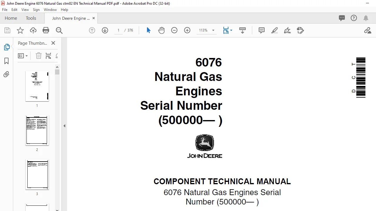
IMAGES PREVIEW OF THE MANUAL:
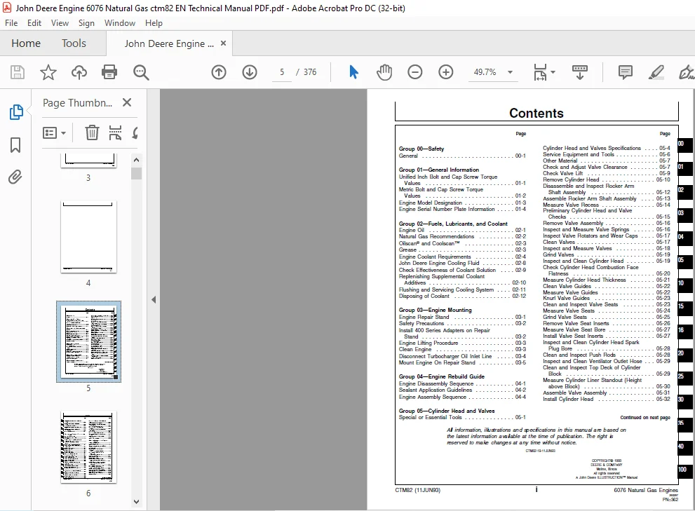
TABLE OF CONTENTS:
John Deere Engine 6076 Natural Gas ctm82 EN Technical Manual PDF
Group 00—Safety
General 00-1
Group 01—General Information
Unified Inch Bolt and Cap Screw Torque
Values01-1
Metric Bolt and Cap Screw Torque
Values01-2
Engine Model Designation 01-3
Engine Serial Number Plate Information01-4
Group 02—Fuels, Lubricants, and Coolant
Engine Oil 02-1
Natural Gas Recommendations 02-2
Oilscan® and Coolscan™ 02-3
Grease02-3
Engine Coolant Requirements02-4
John Deere Engine Cooling Fluid02-8
Check Effectiveness of Coolant Solution 02-9
Replenishing Supplemental Coolant
Additives02-10
Flushing and Servicing Cooling System 02-11
Disposing of Coolant 02-12
Group 03—Engine Mounting
Engine Repair Stand03-1
Safety Precautions03-2
Install 400 Series Adapters on Repair
Stand 03-2
Engine Lifting Procedure03-3
Clean Engine 03-3
Disconnect Turbocharger Oil Inlet Line03-4
Mount Engine On Repair Stand 03-5
Group 04—Engine Rebuild Guide
Engine Disassembly Sequence04-1
Sealant Application Guidelines04-2
Engine Assembly Sequence04-4
Group 05—Cylinder Head and Valves
Special or Essential Tools 05-1
Page
Cylinder Head and Valves Specifications 05-4
Service Equipment and Tools 05-6
Other Material 05-7
Check and Adjust Valve Clearance 05-7
Check Valve Lift 05-9
Remove Cylinder Head05-10
Disassemble and Inspect Rocker Arm
Shaft Assembly 05-12
Assemble Rocker Arm Shaft Assembly 05-13
Measure Valve Recess05-14
Preliminary Cylinder Head and Valve
Checks 05-15
Remove Valve Assembly 05-16
Inspect and Measure Valve Springs 05-16
Inspect Valve Rotators and Wear Caps 05-17
Clean Valves 05-17
Inspect and Measure Valves05-18
Grind Valves 05-19
Inspect and Clean Cylinder Head 05-19
Check Cylinder Head Combustion Face
Flatness05-20
Measure Cylinder Head Thickness05-21
Clean Valve Guides05-22
Measure Valve Guides05-22
Knurl Valve Guides05-23
Clean and Inspect Valve Seats05-23
Measure Valve Seats 05-24
Grind Valve Seats 05-25
Remove Valve Seat Inserts 05-26
Measure Valve Seat Bore05-27
Install Valve Seat Inserts 05-27
Inspect and Clean Cylinder Head Spark
Plug Bore 05-28
Clean and Inspect Push Rods 05-28
Inspect and Clean Ventilator Outlet Hose05-29
Clean and Inspect Top Deck of Cylinder
Block05-29
Measure Cylinder Liner Standout (Height
above Block) 05-30
Assemble Valve Assembly05-31
Install Cylinder Head 05-32
Tighten Flanged-Head Cylinder Head Cap
Screws 05-34
TORQUE-TURN Flanged-Head Cap
Screws 05-35
Install Rocker Arm Assembly05-36
Complete Final Assembly Of Water Pump
Side 05-37
Complete Final Assembly On Exhaust
Manifold Side 05-38
Perform Engine Break-In 05-40
Group 10—Cylinder Block, Liners, Pistons and
Rods
Special or Essential Tools 10-1
Service Equipment and Tools 10-3
Other Material 10-4
Cylinder Block, Liners, Pistons, and Rods
Specifications10-5
Preliminary Liner, Piston, and Rod
Checks10-9
Remove Pistons and Connecting Rods 10-10
Measure Cylinder Liner Standout (Height
above Block) 10-14
Remove Cylinder Liners 10-15
Remove Piston Rings 10-16
Clean Pistons10-17
Clean Cylinder Liners 10-17
Visually Inspect Pistons10-18
Check Piston Ring Groove Wear 10-18
Install Piston Pin in Piston10-19
Visually Inspect Cylinder Liners10-20
Measure Piston Skirt OD 10-21
Measure Oil Control Ring Groove 10-22
Measure Cylinder Liners 10-23
Deglazing Cylinder Liners10-24
Inspect and Measure Connecting Rod
Bearings10-25
Inspect Rod and Cap 10-26
Inspect Piston Pins and Bushings 10-27
Remove Piston Pin Bushing 10-29
Clean and Inspect Connecting Rod Pin
Bore 10-29
Install Piston Pin Bushing in Connecting
Rod 10-31
Remove and Clean Piston Cooling
Orifices 10-32
Inspect and Clean Cylinder Block 10-32
Clean Cylinder Liner O-Ring Bore 10-34
Measure Cylinder Block 10-34
Page
Install Piston Cooling Orifices and Gallery
Plugs10-36
Measure Liner Flange Thickness 10-37
Recheck Cylinder Liner Standout (Height
above Block) 10-37
Install Liner Shims—If Required10-38
Install Cylinder Liner O-Rings and
Packings10-39
Cylinder Liner Manufacturing Date Code
Explanation10-40
Install Cylinder Liners 10-41
Install Pistons and Connecting Rods 10-43
Use TORQUE-TURN Method For Proper
Torque 10-45
Check Engine Rotation for Excessive
Tightness10-46
Complete Final Assembly10-46
Group 15—Crankshaft, Main Bearings and
Flywheel
Special or Essential Tools 15-1
Service Equipment and Tools 15-4
Other Material 15-4
Crankshaft, Main Bearings, and Flywheel
Specifications15-5
Failure Analysis15-7
Remove Crankshaft Rear Oil Seal
Housing
(With Oil Seal Housing Installed) 15-8
Install Crankshaft Rear Oil Seal and
Wear Sleeve
(Without Engine Disassembly)15-10
Inspect Vibration Damper15-11
Check Crankshaft End Play 15-12
Remove Damper Pulley 15-13
Remove Crankshaft Front Oil Seal
(With Timing Gear Cover Installed on
Engine) 15-14
Remove Crankshaft Front Wear Sleeve
(With Timing Gear Cover Installed or
Removed)15-15
Install Crankshaft Front Wear Sleeve 15-16
Install Crankshaft Front Oil Seal
(With Timing Gear Cover Installed)15-17
Remove Timing Gear Cover15-17
Inspect, Measure and Repair Flywheel 15-18
Check Flywheel Housing Face Run-Out 15-18
Check Flywheel Face Flatness 15-19
Check Pilot Bearing Bore Concentricity 15-19
Remove Flywheel 15-20
Remove SAE 1 and SAE 2 Flywheel
Housing 15-20
Remove SAE 3 Flywheel Housing 15-21
Replace Flywheel Ring Gear15-21
Remove Rear Oil Seal Housing and
Wear
Sleeve (With Engine Disassembled)15-22
Remove Crankshaft Main Bearings15-23
Check Main Bearing Clearance15-24
Remove Crankshaft15-25
Remove and Inspect Crankshaft Gear15-26
Inspect Crankshaft 15-27
Measure Assembled ID of Bearings And
OD Of Crankshaft Journals15-28
Main Bearing Cap Line Bore
Specifications 15-30
Crankshaft Grinding Guidelines 15-31
Thrust Bearing New Part Specifications 15-33
Crankshaft Grinding Specifications15-34
Replace Crankshaft Oil Pump Drive Gear15-35
Inspect Thrust Bearings 15-36
Remove and Clean Piston Cooling
Orifices 15-36
Install Main Bearings 15-37
Install Crankshaft Gear15-38
Install Crankshaft15-39
Install Crankshaft Rear Oil Seal Housing15-40
Check Oil Seal Housing Runout15-41
Crankshaft Rear Oil Seal And Wear
Sleeve Handling Precautions 15-42
Install Crankshaft Rear Oil Seal and
Wear Sleeve Assembly15-43
Install Timing Gear Cover15-44
Install SAE 3 Flywheel Housing15-45
Install Flywheel 15-46
Install SAE 1 and SAE 2 Flywheel
Housing 15-47
Install Damper Pulley Assembly15-48
Complete Final Assembly15-48
Group 16—Camshaft and Timing Gear Train
Special or Essential Tools 16-1
Other Material 16-3
Camshaft and Timing Gear Train
Specifications16-4
Check Valve Lift 16-5
Check Camshaft End Play 16-6
Measure Camshaft Drive
Gear-to-Crankshaft Gear Backlash16-6
Remove Timing Gear Cover 16-7
Remove Camshaft16-8
Page
Remove Camshaft Gear and Ignition
Timing Wheel 16-10
Measure Thrust Washer Thickness16-10
Inspect and Measure Camshaft Followers16-11
Visually Inspect Camshaft16-11
Measure Camshaft Journal OD and
Bushing ID 16-12
Measure Camshaft Lobe Lift16-12
Install Camshaft Gear and Ignition Timing
Wheel16-13
Service Camshaft Bushings using
JDG602 Adapter Set16-14
Service Camshaft Bushings using
JDG606 Adapter Set16-16
Install Camshaft 16-17
Install Thrust Washer and Timing Gear
Cover16-19
Complete Final Assembly16-20
Group 20—Lubrication System
Other Material 20-1
Lubrication System Specifications20-1
Drain Engine Oil and Remove Oil Pan 20-2
Oil Filter and Oil Conditioning Housing
Assembly 20-3
Remove Oil Filter and Oil Conditioning
Housing20-4
Remove, Inspect, and Install Valves from
Oil Conditioning Housing20-5
Install Oil Filter and Oil Conditioning
Housing20-6
Remove Engine Oil Cooler20-7
Clean, Inspect, and Install Engine Oil
Cooler 20-8
Engine Oil Pump Assembly—Deep and
Standard Sump20-9
Check Crankshaft Gear-To-Oil Pump
Drive Gear Backlash20-10
Remove Engine Oil Pump20-10
Inspect and Clean Oil Pump20-11
Check Drive Shaft End Play20-11
Check Drive Shaft Side Movement20-12
Check Pumping Gear Backlash20-12
Inspect Oil Pump Drive Gear20-13
Install Engine Oil Pump20-13
Install Oil Pan20-15
Group 25—Cooling System
Special or Essential Tools 25-1
Other Material 25-2
Cooling System Specifications25-3
Service Equipment and Tools 25-4
Remove Engine Water Pump 25-5
Disassemble Engine Water Pump25-6
Inspect Water Pump Parts 25-8
Assemble Engine Water Pump25-9
Install Engine Water Pump 25-11
Remove and Install Auxiliary Water Pump25-12
Inspect and Clean Aftercooler Orifice
Fitting25-13
Remove and Test Thermostats 25-13
Install Thermostats 25-14
Remove Water Manifold 25-15
Water Manifold Mounted Fixed Fan Drive
Assembly25-16
Install Water Manifold 25-17
Remove Coolant Heater 25-17
Install Coolant Heater 25-18
Complete Final Assembly25-19
Group 30—Air Intake And Exhaust System
Special or Essential Tools 30-1
Other Material 30-1
Air Intake and Exhaust System
Specifications30-1
Extending Turbocharger Life 30-3
Remove Turbocharger 30-6
Turbocharger Failure Analysis30-7
Turbocharger Seven-Step Inspection30-9
Perform Radial Bearing Clearance Test 30-13
Perform Axial Bearing End Play Test 30-14
Repair Turbocharger30-14
Prelube Turbocharger 30-15
Install Turbocharger30-16
Remove Aftercooler Assembly 30-17
Inspect and Repair Aftercooler 30-18
Inspect and Repair Intake Manifold and
Aftercooler Cover30-19
Assemble and Install Aftercooler
Assembly30-20
Remove, Inspect, and Install Exhaust
Manifold30-22
Group 35—Fuel System
Other Material 35-1
Fuel System Specifications35-1
Replace Natural Gas Filter35-2
Remove and Install 20 PSI Carburetor 35-3
Remove and Install 4 PSI Carburetor 35-4
Replace Diaphragm(s) in Carburetor35-5
Service Natural Gas Regulator35-6
Page
Group 40—Ignition System and Electronic
Governor
Special or Essential Tools 40-1
Other Materials40-2
Ignition System and Electronic Governor
Specifications40-2
Check Ignition Timing Indicator
Alignments40-3
Remove and Install Spark Plugs 40-4
Inspect, Clean, and Adjust Spark Plugs40-4
Remove and Install Ignition Timing
Sensor40-5
Remove and Install Ignition Sensor Plate 40-5
Remove and Install Manifold Absolute
Pressure Sensor40-6
Remove and Install Charge Air
Temperature Switch40-6
Remove and Install Ignition Coils40-7
Remove and Install Ignition Control Unit 40-7
Remove and Install Ignition System
Mounting Plate 40-8
Remove and Install Electronic Governor40-8
Remove and Install Throttle Actuator40-9
Remove and Install Electronic Governor
Speed Sensor40-10
Remove and Install Governor and Ignition
System Wiring Harness40-11
Replace Weather Pack™ Connector 40-12
Install Weather Pack™ Contact40-13
Group 100—Engine Tune-Up and Break-In
Altitude Compensation Guideline100-1
Preliminary Engine Testing 100-1
General Tune-Up Recommendations 100-2
Dynamometer Test 100-3
Engine Break-In Guidelines 100-3
Engine Break-In Instructions100-4
Check Crankcase Ventilation System 100-4
Check Air Intake System 100-5
Check Exhaust System100-5
Check and Service Cooling System100-6
Check Electrical System 100-8
Group 105—Engine System Operation and Test
Special or Essential Tools105-1
Engine Test Specifications105-2
Engine—Sectional View 105-4
General Engine Description 105-5
How the Lubrication System Works105-6
How the Cooling System Works 105-10
Head Gasket Joint Construction and
Operation105-14
Diagnosing Head Gasket Joint Failures105-16
Head Gasket Inspection and Repair
Sequence105-19
Test Engine Compression Pressure 105-21
Check Engine Oil Pressure105-22
Pressure Test Cooling System and
Radiator Cap105-23
Inspect Thermostat and Test Opening
Temperature105-24
Group 110—Air Intake System Operation and
Test
Special or Essential Tools110-1
Service Equipment and Tools110-1
Air Intake and Exhaust System Test
Specifications 110-1
How the Air Intake and Exhaust System
Works110-2
Air Cleaner Operation 110-2
Diagnosing Turbocharger Malfunctions110-3
How The Turbocharger Works 110-4
How The Turbocharger is Lubricated 110-4
How The Aftercooler Works 110-5
Check Intake Manifold Pressure110-6
Troubleshoot Charge Air Temperature
Switch (CATS)110-7
How the Pyrometer Shutdown Works110-8
Adjust Pyrometer Shutdown Temperature110-9
Group 115—Fuel System Operation and Test
Service Equipment and Tools115-1
Fuel System Test Specifications115-1
How the Fuel System Works115-2
Adjust Low Idle Speed115-6
Adjust Low Idle Fuel Mixture115-6
Adjust Air/Fuel Mixture115-7
Adjust Regulator Differential Gas
Pressure115-8
Group 120—Ignition System Operation and Test
Special or Essential Tools120-1
Service Equipment and Tools120-1
How the Ignition System Works120-2
Ignition Control Unit (ICU) Self-Diagnostic
Test 120-4
Troubleshoot Manifold Absolute Pressure
(MAP) Sensor120-5
Troubleshoot Primary and Secondary
Ignition System120-6
Troubleshoot Ignition Timing and
Governor Speed Sensors 120-8
Adjust Overspeed Shutdown120-9
Adjust Ignition Timing120-10
How the Electronic Governor Works120-11
Troubleshoot Remote Speed
Potentiometer120-12
Troubleshoot Throttle Actuator120-13
Adjust Electronic Governor120-14
Wiring Diagrams
Instrument Panel/Engine 120-16
Reading a Wiring Diagram 120-17
Wiring Harness Connectors 120-18
Ignition System and Electronic
Governor 120-19
Primary Ignition System 120-20
Group 125—Engine Diagnostics
Diagnose Engine Malfunctions 125-1
Group 199—Dealer Fabricated Tools
How to Make Tools199-1
Cylinder Liner Holding Fixture 199-1
Index
PLEASE NOTE:
- This is the SAME MANUAL used by the dealerships to diagnose your vehicle
- No waiting for couriers / posts as this is a PDF manual and you can download it within 2 minutes time once you make the payment.
- Your payment is all safe and the delivery of the manual is INSTANT – You will be taken to the DOWNLOAD PAGE.
- So have no hesitations whatsoever and write to us about any queries you may have : heydownloadss @gmail.com
S.V