John Deere Engines 8955 Component ctm10 EN Technical Manual PDF
Original price was: $78.00.$26.95Current price is: $26.95.
John Deere Engines 8955 Component ctm10 EN Technical Manual PDF
Description
John Deere Engines 8955 Component ctm10 EN Technical Manual PDF
FILE DETAILS:
John Deere Engines 8955 Component ctm10 EN Technical Manual PDF
Language : English
Pages :388
Downloadable : Yes
File Type : PDF
Size:19.0 MB
DESCRIPTION:
John Deere Engines 8955 Component ctm10 EN Technical Manual PDF
Introduction and Safety Information
ABOUT THIS MANUAL
- This Component Technical Manual (CTM-10) covers the recommended repair procedure for all 15.65 L (955 cu. in.) Engines produced in Waterloo, Iowa. Before beginning repair of an engine, clean engine and mount in a safety approved repair stand. (See Group 03.)
- This technical manual contains SI Metric equivalents which precede the U.S. Customary units of measure. Nearly all the parts and fasteners used in 700-Series engines are metric except the tapped holes (for clutch housing) in flywheel housing and some hardware items which are in U.S
- . Customary units. Some components of this engine may be serviced without removing the engine from the machine. Refer to the specific machine technical manuals for information on components that can be serviced without removing the engine from the machine and for engine removal/installation procedures.
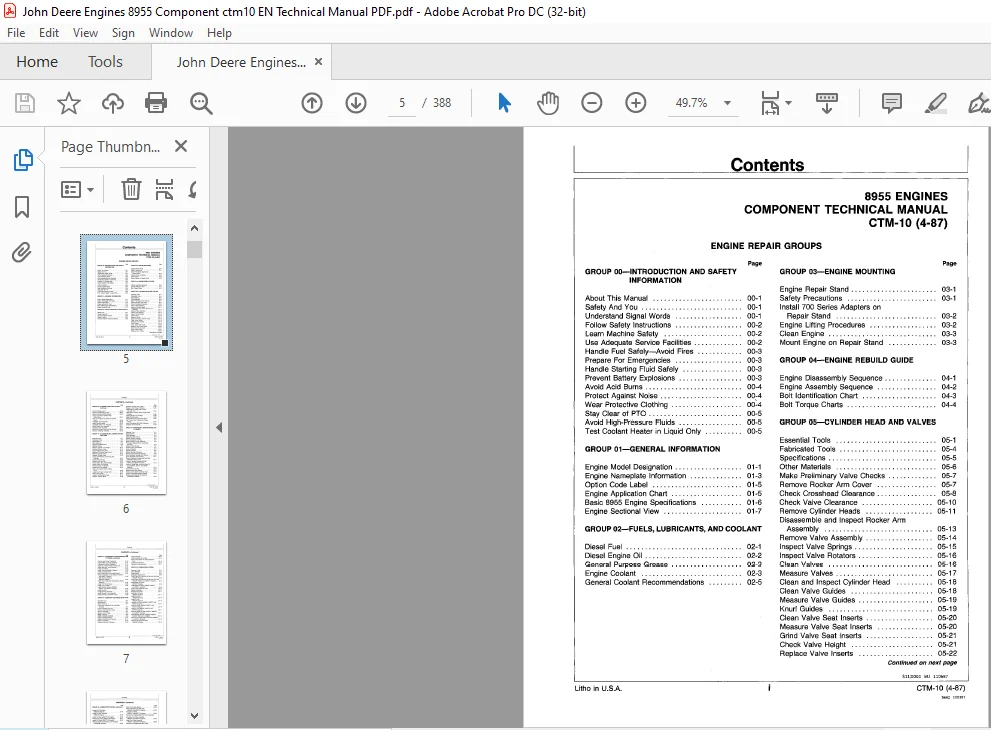
TABLE OF CONTENTS:
John Deere Engines 8955 Component ctm10 EN Technical Manual PDF
GROUP DO-INTRODUCTION AND SAFETY
INFORMATION
Page
About This Manual 00-1
Safety And You 00-1
Understand Signal Words 00-1
Follow Safety Instructions 00-2
Learn Machine Safety 00-2
Use Adequate Service Facilities 00-2
Handle Fuel Safely-Avoid Fires 00-3
Prepare For Emergencies 00-3
Handle Starting Fluid Safely 00-3
Prevent Battery Explosions 00-3
Avoid Acid Burns 00-4
Protect Against Noise 00-4
Wear Protective Clothing 00~4
Stay Clear of PTO 00-5
Avoid High-Pressure Fluids 00-5
Test Coolant Heater in Liquid Only 00-5
GROUP 01-GENERAL INFORMATION
Engine Model Designation 01-1
Engine Nameplate Information 01-3
Option Code Label 01-5
Engine Application Chart 01-5
Basic 8955 Engine Specifications 01-6
Engine Sectional View 01-7
GROUP 02-FUELS, LUBRICANTS, AND COOLANT
Diesel Fuel 02-1
Diesel Engine Oil 02-2
General Purpose Grease 02-3
Engine Coolant 02-3
General Coolant Recommendations 02-5
Litho in USA
Page
GROUP 03-ENGINE MOUNTING
Engine Repair Stand 03-1
Safety Precautions 03-1
Install 700 Series Adapters on
Repair Stand 03-2
Engine Lifting Procedures 03-2
Clean Engine 03-3
Mount Engine on Repair Stand 03-3
GROUP 04-ENGINE REBUILD GUIDE
Engine Disassembly Sequence 04-1
Engine Assembly Sequence 04-2
Bolt Identification Chart 04-3
Bolt Torque Charts 04-4
GROUP 05-CYLINDER HEAD AND VALVES
Essential Tools 05-1
Fabricated Tools 05-4
Specifications 05-5
Other Materials 05-6
Make Preliminary Valve Checks 05-7
Remove Rocker Arm Cover 05-7
Check Crosshead Clearance 05-8
Check Valve Clearance 05-10
Remove Cylinder Heads 05-11
Disassemble and Inspect Rocker Arm
Assembly 05-13
Remove Valve Assembly 05-14
Inspect Valve Springs 05-15
Inspect Valve Rotators 05-16
Clean Valves 05-16
Measure Valves 05-17
Clean and Inspect Cylinder Head 05-18
Clean Valve Guides 05-18
Measure Valve Guides 05-19
Knurl Guides 05-19
Clean Valve Seat Inserts 05-20
Measure Valve Seat Inserts 05-20
Grind Valve Seat Inserts 05-21
Check Valve Height 05-21
Replace Valve Inserts 05-22
Continued on next page
S11;0000 BU 110687
CTM-1 o (4-87)
S44;I 100387
Contents
CONTENTS-Continued
Page
GROUP OS-CYLINDER HEAD AND VALVESContinued
Install Oversize Inserts 05-23
Service Crossheads and Pins 05-23
Service Injection Nozzle Sleeves 05-25
Inspect and Clean Cylinder Head
Nozzle Bore 05-27
Clean and Inspect Top Decks of Cylinder
Block 05-28
Assemble Valve Assembly 05-28
Install Cylinder Heads 05-29
Assemble Rocker Arm Assembly 05-31
Install Rocker Arm Assembly 05-31
,Complete Final Assembly 05-32
Retorque Cylinder Head and Cap Screws 05-33
Service Ventilating Assembly 05-33
GROUP 10-CYLINDER BLOCK, LINERS, PISTONS
AND RODS
Essential Tools 10-1
Fabricated Tools 10-3
Specifications 10-4
Other Materials 10-5
Diagnosing Malfunctions 10-6
Remove Pistons 10-7
Measure Cylinder Liner Height 10-12
Remove Cylinder Liners 10-12
Inspect Pistons and Liners 10-15
Measure Oil Control Ring Groove 10-21
Measure Cylinder Liners 10-22
Deg laze Cylinder Liners 10-23
Inspect and Measure Connecting Rod
Bearings 10-23
Inspect Rod and Cap 10-25
Measure Rod and Cap 10-25
Inspect Piston Pins and Bushings 10-25
Inspect Piston Pin Bushing 10-26
Remove Piston Pin Bushing 10-27
Install Piston Pin Bushing 10-28
Clean and Inspect Piston Cooling
Lines 10-28
Inspect and Clean Cylinder Block 10-29
Clean O-Ring Bore 10-31
Inspect Cylinder Block Plugs 10-31
Measure Cylinder Block 10-32
Litho in USA Ii
Page
Recheck Cylinder Liner Height 10-33
Measure Liner Flange Thickness 10-33
Install Piston Cooling Lines-Using
JDG-248 Tool 10-34
Install Piston Cooling Lines-Using Feeler
Gauges · 1 0-35
Install Cylinder Liner O-Rings 10-36
Install Cylinder Liners 10-36
Install Pistons and Connecting Rods 10-37
Use “Torque-Turn” Method for Proper
Torque 10-41
Check Connecting Rod Side Clearance 10-41
Complete Final Assembly 10-42
GROUP 15-CRANKSHAFT, MAIN BEARINGS, AND
FLYWHEEL
Essential Tools , 15-1
Specifications 1 5-2
Other Materials 15-3
Diagnosing Malfunctions 15-3
Inspect Vibration Damper 15-4
Check Crankshaft End Play 15-5
Remove Damper Pulley Assembly 15-6
Preliminary Disassembly for Crankshaft
Removal 15-6
Remove Front Oil Seal 15-7
Remove Front Wear Sleeve 15-7
Remove Flywheel 15-7
Inspect Flywheel 15-8
Service Flywheel Ring Gear 15-8
Service Clutch Shaft Pilot Bushing 15-9
Check Flywheel Housing Face Runout 15-10
Check Flywheel Face Flatness 15-11
Remove Flywheel Housing and Rear Seal
(8955AR Engines Only) • 15-11
Remove Flywheel Housing (8955AF,
8955TF and 8955TT Engines) 15-12
Remove Timing Gear Cover and Rear Oil
Seal (8955AF, 8955TF, and 8955TT
Engines) 15-13
Remove Rear Oil Seal 15-13
Remove Rear Wear Sleeve 15-13
Remove and Inspect Crankshaft Gear 15-14
Remove Crankshaft Bearing Support 15-14 ·
Measure Main Bearing Oil Clearance
(Crankshaft Installed) 15-15
S11;0000 BV 300687
CTM-10 (4-87)
S44;II 100)87
Contents
CONTENTS-Continued
Page
GROUP 15-CRANKSHAFT, MAIN BEARINGS, AND
FLYWHEEL-Continued
Remove and Inspect Crankshaft 15-15
Inspect Main and Thrust Bearings 15-17
Crankshaft Grinding Guidelines 15-17
Clean and Inspect Piston Cooling Lines 15-19
Install Main and Thrust Bearings 15-19
Install Crankshaft 15-20
Install Crankshaft Bearing Support 15-20
Install Crankshaft Gear 15-21
Align Crankshaft and Camshaft Gears 15-22
Install Timing Gear Cover (8955AF, 8955TF,
and 8955TT Engines) 15-23
Install Flywheel Housing
(8955AR Engines) 15-23
Install Rear Crankshaft Oil Seal/ Wear Sleeve
Assembly 15-24
Install Front Wear Sleeve 15-25
Install Front Oil Seal 15-25
Install Flywheel Housing (8955AF,
8955TF, and 8955TT Engines) 15-26
Install Flywheel 15-27
Complete Final Assembly 15-27
Install Damper Pulley Assembly 15-28
Recheck Engine Camshaft Timing 15-29
GROUP 16-CAMSHAFT AND TIMING GEAR TRAIN
Essential Tools 16-1
Specifications 16-3
Check Valve Lift 16-4
Preliminary Disassembly for Camshaft
Removal 16-5
Check Camshaft End Play 16-6
Remove Camshaft Drive Gear 16-6
Remove Camshaft 16-7
Measure Thrust Plate 16-8
Measure Spacer 16-8
Repair Camshaft Bushings 16-9
Inspect Camshaft Gears 16-10
Inspect Camshaft and Followers 16-11
Measure Camshaft 16-12
Measure Camshaft Followers 16-12
Litho in USA iii
Page
Install Camshaft 16-13
Install Camshaft Drive Gear 16-14
Align Timing Marks on Crankshaft Gear
Train 16-15
Install Cam Followers 16-16
Complete Final Assembly ~ 16-17
GROUP 20-LUBRICATION SYSTEM
Essential Tools 20-1
Other Materials 20-1
Specifications 20-2
Diagnosing Malfunctions 20-3
Drain Engine Oil, Remove Oil Pan and Oil Pump
(8955AR Engines) 20-4
Drain Engine Oil, Remove Oil Pan and Oil Pump
{8955AF, 8955TF, and 8955TT Engines) 20-5
Disassemble Oil Pump
(8955AR Engines) 20-6
Disassemble Oil Pump (8955AF, 8955TF,
and 8955TT Engines) 20-8
Inspect and Repair Oil Pump 20-10
Replace Bushings 20-1 O
Replace Idler Shaft 20-11
Assemble Oil Pump
(8955AR Engines) 20-11
Install Oil Pump
(8955AR Engines) 20-12
Install Oil Pan
(8955AR Engines) 20-13
Assemble Oil Pump (8955AF, 8955TF, and
8955TT Engines) 20-14
Install Oil Pump {8955AF, 8955TF, and
8955TT Engines) 20-16
Install Oil Pan (8955AF, 8955TF, and
8955TT Engines) 20-17
Remove Bypass Oil Filter (8955AF, 8955AR,
and 8955TF Engines) 20-17
Install Bypass Oil Filter Assembly (8955AF,
8955AR, and 8955TF Engines 20-18
Remove and Install Engine Oil Filters (8955AF
and 8955TF Engines) 20-18
Remove Oil Filters and Base
(8955AR Engines) 20-18
S 11;0000 BW 300(,87
CTM-10 (4-87)
S44;UI 100387
Contents
CONTENTS-Continued
Page
GROUP 20-LUBRICATION SYSTEM-Continued
Inspect Oil Filter Base
(8955AR Engines) 20-19
Install Oil Filter Assembly
(8955AR Engines) 20-19
Remove Oil Filters (8955TT-02 Engine) 20-20
Install Oil Filters (8955TT-02 Engine) 20-20
Remove Oil Filters (8955TT-03 Engine) 20-21
Install Oil FIiters (8955TT-03 Engine) 20-21
Remove Engine Oil Cooler and Oil Pressure
Regulating Housings 20-22
Remove and Inspect Pressure Regulating
Housing Valves 20-25
Disassemble and Inspect Oil Cooler 20-26
Assemble Oil Pressure Regulating
Housing 20-27
Assemble Oil Cooler 20-28
Assemble Oil Cooler and Pressure Regulating
Housings 20-29
GROUP 25-COOLING SYSTEM
Essential Tools 25-1
Specifications 25-3
Check Water Pump Shaft End Play 25-4
Remove Water Pump 25-5
Disassemble Water Pump 25-6
Assemble Water Pump 25-8
Install Water Pump 25-13
Remove Thermostats and Water Outlet
Manifolds 25-14
Clean and Inspect Water Outlet Manifold
Parts 25-15
Test Thermostats 25-16
Install Water Outlet Manifolds and
Thermostats 25-16
Remove and Clean Coolant Filter Conditioner
Assembly (8955AR and 8955TT Engines) 25-18
Install Coolant Filter Conditioner Assembly
8955AR and 8955TT Engines) 25-19
Remove and Clean Coolant Filter Conditioner
Assembly (8955TF and 8955AF Engines) 25-20
Install Coolant Filter Conditioner Assembly
(8955AF and 8955TF Engines) 25-21
Litho in USA iv
Page
Bleed the Cooling System 25-22
Check Alternator and Fan Belts
(8955AF and 8955TF Engines) 25-22
Remove Fan Belts
(8955AF and 8955TF Engines) 25-23
Remove and Disassemble Fan Pulley Assembly
(8955AF and 8955TF Engines) 25-23
Assemble Fan Pulley Assembly
(8955AF and 8955TF Engines) 25-25
Install Fan Pulley Assembly
(8955AF and 8955TF Engines) 25-26
Remove and Disassemble Idler Pulley
(8955AF and 8955TF Engines) 25-26
Assemble Idler Pulley
(8955AF and 8955TF Engines) 25-27
Install Idler Pulley
(8955AF and 8955TF Engines) 25-27
GROUP 30-AIR INTAKE AND EXHAUST SYSTEMS
Essential Tools 30-1
Fabricated Tools 30-2
Specifications 30-3
Diagnosing Turbocharger Malfunctions 30-4
Remove Turbocharger 30-6
Turbocharger Seven-Step Inspection 30-7
A-Compressor Housing Inlet and Compressor
Wheel 30-9
8-Compressor Housing Outlet 30-9
C-Turbine Housing Inlet 30-10
D-Turbine Housing Outlet and Turbine
Wheel 30-10
E-External Center Housing and Joints 30-11
F-lnternal Center Housing 30-11
G-Turbo Bench Test 30-11
Make Radial Bearing Test 30-13
Make Axial End Play Bearing Test 30-13
Disassemble Turbocharger 30-14
Clean Turbocharger Parts 30-19
Inspect and Repair Turbocharger Parts 30-19
Inspection Wear-Tolerance Chart 30-20
Assemble AiResearch/ Garrett-TV-61
Turbocharger 30-21
Install Turbocharger 30-25
Remove and Service Air Intake Manifold-
8955T Engines 30-28
S11;0000 SX 110&87
CTM-10 (4-87)
S44;IV 100387
Contents
CONTENTS-Continued
Page
GROUP 30-AIR INTAKE AND EXHAUST
SYSTEMS-Continued
Assemble and Install Air lntake-
8955T Engines 30-29
Remove Air Intake System and Aftercoolers-
8955A Engines 30-29
Inspect Center Manifold-8955A Engines 30-32
Inspect and Repair Aftercoolers-
8955A Engines 30-32
Install Aftercoolers and Air Intake System-
8955A Engines 30-33
Remove Exhaust Manifold Assembly 30-35
Clean and Inspect Exhaust Manifolds 30-36
Install Exhaust Manifold Assembly 30-37
GROUP 35-FUEL SYSTEM
Essential Tools 35-1
Specifications 35-4
Relieve System Pressure 35-5
Remove and Inspect Barnes Fuel Supply
Pump-8955AF, TF Engines, (Serial
No 0000-3076) 35-6
Adjust John Barnes Fuel Supply Pump Relief
Valve-8955AF, TF Engines 35-7
Remove Fuel Filters, Water Separator and
Filter Body-8955AF, TF Engines, (Serial
No 0000-3076} 35-8
Inspect and Clean Fuel Filter Body 35-9
Install Fuel Filter Body and Filters-
8955AF, TF Engines, (Serial No
0000-3076) 35-9
Replace Bosch Fuel Supply Pump-8955F,
TF Engines 35-10
Remove Fuel Filters, Water Separator, and
Filter Body-8955AF, TF Engines 35-10
Inspect and Clean Fuel Filter Body 35-11
Install Water Separator-8955AF,
TF Engines 35-12
Install Fuel Filter Body and Filter-8955TF,
AF Engines 35-12
Replace Water Separator Fuel Filter-8955AF,
TF Engines 35-12
Remove and Disassemble Water Separator-
8955AF, TF Engines 35-13
Litho in USA V
Page
Assemble and Install Water Separator-8955AF,
TF Engines 35-14
Bleed the Fuel System : 35-15
Service Return Fuel and Overflow Valves
Engine Serial No (0000-2235) 35-16
Service Return Fuel and Overflow Valves-
Engine Serial No (2236- ) 35-17
General Information for Aneroid-Regulator
Governor 35-19
Repair Aneroid-Regular Governor 35-20
Remove Hydraulic Aneroid Activator-Regular
Governor 35-20
Disassemble and Repair Hydraulic Aneroid
Activator-Regular Governor 35-21
Assemble Hydraulic Aneroid Activator-Regular
Governor 35-21
Remove and Inspect Fuel Shut-Off Solenoid
(8955AF, TF, TT Engines with Regular
Governor) 35-22
Install and Adjust Fuel Shut-Off Solenoid
(8955AF, TF, TT Engines with Regular
Governor) 35-23
Remove Fuel Injection Pump 35-24
Repair Fuel Injection Pump 35-28
Service Electric Governor
(8955AF, TF Engines) 35-29
Prepare Engine for Installation of Injection
Pump · 35-29
Install Fuel Injection Pump 35-30
Remove and Inspect Fuel Shut-Off Solenoid
(8955AF, TF, TT Engines with Regular
Governor) 35-35
Install and Adjust Fuel Shut-Off Solenoid
(8955AF, TF, TT Engines with Regular
Governor) 35-35
Remove Fuel Injection Nozzles 35-36
Test Fuel Injection Nozzles 35-37
Make Opening Pressure Test 35-38
Make Leakage Test 35-39
Make Chatter and Spray Pattern Test 35-40
Disassemble Fuel Injection Nozzle 35-41
Clean and Inspect Fuel Injection Nozzle
Assembly 35-42
Perform Nozzle Slide Test 35-43
Clean Spray Orifices 35-43
Inspect Nozzle Holder 35-44
Assemble Hydraulic Aneroid Activator 35-46
Assemble Fuel Injection Nozzle 35-46
511;0000 BY 1106B7
CTM-10 (4-87)
S44;1/ 100387
Contents
CONTENTS-Continued
GROUP 35-FUEL SYSTEM-Continued
Inspect and Clean Cylinder Head Nozzle
Page
Bore 35-48
Install Fuel Injection Nozzles 35-49
Install Fuel Injection Lines 35-50
GROUP 100-TUNE-UP
General Tune-Up Recommendations 100-1
Preliminary Engine Testing 100-2
Check Crankcase Ventilation System 100-3
Check Air Intake System 100-3
Check Exhaust System 100-3
Check and Service Cooling System 100-4
Check Electrical System 100-6
GROUP 105-ENGINE SYSTEM OPERATION AND
TESTS
Essential Tools 105-1
General Information 105-2
Cooling System 105-3
Lubrication System 105-5
Pressure Regulating System 105-6
Dynamometer Test 105-8
Engine Break-In Instructions 105-9
Diagnose Engine Malfunctions 105-10
Test Compression Pressure 105-17
Check Crosshead Clearance 105-19
Check Valve Clearance 105-22
Check Valve Lift 105-23
Check Crankshaft End Play 105-23
Check Damper Runout 105-24
Check Oil Pressure 105-24
Test Radiator and Cap 105-25
GROUP 110-AIR INTAKE SYSTEM OPERATION
AND TESTS
Essential Tools 110-1
Specifications 110-1
How the Air Intake System Works 110-2
How the Air Cleaner Works 110-3
Diagnosing System Malfunctions 110-4
How the Turbocharger Works 110-5
Diagnosing Turbocharger Malfunctions 110-6
How the Aftercooler Works-8955AF Only 110-7
Check Intake Manifold Pressure 110-8
Litho in USA vi
Page
GROUP 115-FUEL SYSTEM OPERATION AND
TESTS
Essential Tools 115-1
Specifications 115-2
How the Fuel System Works 115-3
Diagnose Fuel System Malfunctions 115-4
Test Fuel System Pressure-John Barnes
Fuel Supply Pump 115-7
Test Fuel Supply Pressure-Robert Bosch
Fuel Supply Pump 115-8
Adjust John Barnes Fuel Supply Pump Relief
Valve-8955AF, TF, Engines 115-9
How the Fuel Filter Works 115-10
Bleed the Fuel System 115-11
Fuel Injection Pump 115-12
How the Fuel Injection Pump Works 115-13
Diagnosing Injection Pump Malfunctions 115-14
Adjust Electric Fuel Shut-Off-Regular
Governor 115-15
Check and Adjust Pump Timing 115-15
Test Slow ldle-8 to 10% Regular
Governor 115-18
Adjust Slow ldle-8 to 10% Regular
Governor 115-19
Test Fast ldle-8 to 10% Regular
Governor 115-21
Adjust Fast ldle—8 to 10% Regular
Governor 115-21
Aneroid General Information 115-22
How the Aneroid Works-8 to 10% Regular
Governor 115-23
Diagnosing Aneroid Malfunctions-a to 10%
Regular Governor 115-24
How the Hydraulic Aneroid Activator Works-
8 to 10% Regular Governor 115~25
Diagnose Malfunction-Hydraulic Aneroid
Activator 115-26
Fuel Injection Nozzles General
Information 115-27
How the Fuel Injection Nozzle Works 115-28
Diagnose Malfunction-Fuel Injection
Nozzle 115-29
Test Fuel Injection Nozzles
(Engine Running) 115-30
Fuel Drain Back Test
Procedure 115-30
IMAGES PREVIEW OF THE MANUAL:
PLEASE NOTE:
- This is not a physical manual but a digital manual – meaning no physical copy will be couriered to you. The manual can be yours in the next 2 mins as once you make the payment, you will be directed to the download page IMMEDIATELY.
- This is the same manual used by the dealers inorder to diagnose your vehicle of its faults.
- Require some other service manual or have any queries: please WRITE to us at [email protected]
S.M