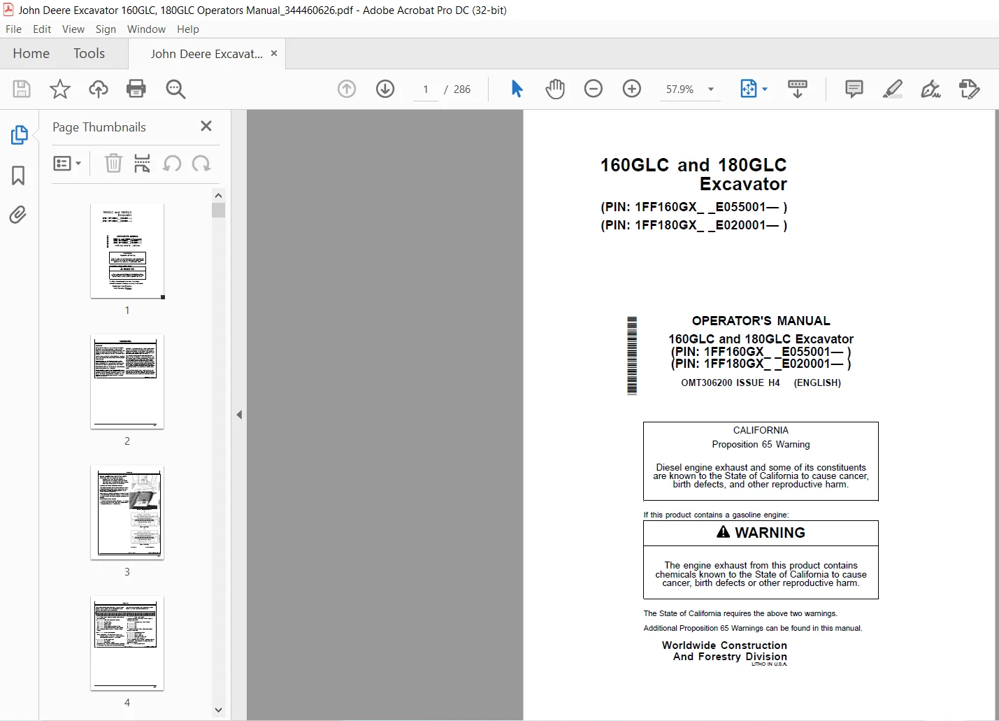
John Deere Excavator 160GLC and 180GLC Operators Manual – PDF DOWNLOAD
Original price was: $78.00.$28.95Current price is: $28.95.
John Deere Excavator 160GLC and 180GLC Operators Manual – PDF DOWNLOAD
(PIN: 1FF160GX_ _E055001— )
(PIN: 1FF180GX_ _E020001— )
OMT306200 ISSUE H4
Description
John Deere Excavator 160GLC and 180GLC Operators Manual – PDF DOWNLOAD
DESCRIPTION:
(PIN: 1FF160GX_ _E055001— )
(PIN: 1FF180GX_ _E020001— )
OMT306200 ISSUE H4
John Deere Excavator 160GLC and 180GLC Operators Manual – PDF DOWNLOAD
Foreword
- READ THIS MANUAL carefully to learn how to operate and service your machine correctly. Failure to do so could result in personal injury or equipment damage. This manual and safety signs on your machine may also be available in other languages; see your John Deere dealer to order.
- THIS MANUAL SHOULD BE CONSIDERED a permanent part of your machine and should remain with the machine when you sell it. MEASUREMENTS in this manual are given in both metric and customary U.S. unit equivalents. Use only correct replacement parts and fasteners.
- Metric and inch fasteners may require a specific metric or inch wrench. RIGHT-HAND AND LEFT-HAND sides are determined by facing in the direction of forward travel. WRITE PRODUCT IDENTIFICATION NUMBERS (P.I.N.) in the Machine Numbers section.
- Accurately record all the numbers to help in tracing the machine if machine is ever stolen. Your dealer also needs these numbers when you order parts. File the identification numbers in a secure place off the machine. WARRANTY is provided as part of John Deere’s support program for customers who operate and maintain their equipment as described in this manual.
- The warranty is explained on the warranty certificate or statement which you should have received from your dealer. This warranty provides you the assurance that John Deere will back its products where defects appear within the warranty period. In some circumstances, John Deere also provides field improvements, often without charge to the customer, even if the product is out of warranty.
- Should the equipment be abused, or modified to change its performance beyond the original factory specifications, the warranty will become void and field improvements may be denied. Setting fuel delivery above specifications or otherwise overpowering machines will result in such action. If you are not the original owner of this machine, it is in your interest to contact your local John Deere dealer to inform them of this unit’s serial number. This will help John Deere notify you of any issues or product improvements
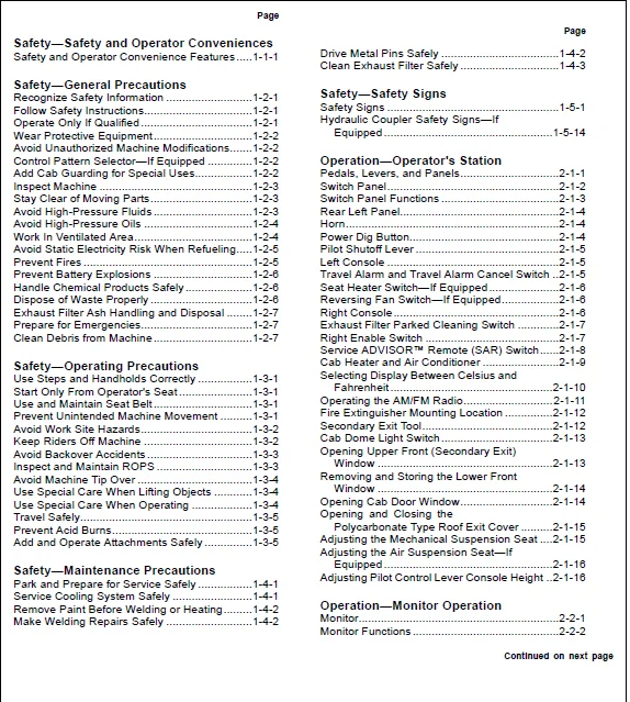
TABLE OF CONTENTS:
John Deere Excavator 160GLC and 180GLC Operators Manual – PDF DOWNLOAD
Safety—Safety and Operator Conveniences
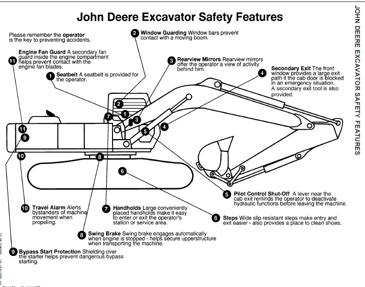
Safety and Operator Convenience Features 1-1-1
Safety—General Precautions
Recognize Safety Information 1-2-1
Follow Safety Instructions1-2-1
Operate Only If Qualified 1-2-1
Wear Protective Equipment1-2-2
Avoid Unauthorized Machine Modifications1-2-2
Control Pattern Selector—If Equipped 1-2-2
Add Cab Guarding for Special Uses1-2-2
Inspect Machine 1-2-3
Stay Clear of Moving Parts1-2-3
Avoid High-Pressure Fluids 1-2-3
Avoid High-Pressure Oils 1-2-4
Work In Ventilated Area1-2-4
Avoid Static Electricity Risk When Refueling1-2-5
Prevent Fires 1-2-5
Prevent Battery Explosions 1-2-6
Handle Chemical Products Safely 1-2-6
Dispose of Waste Properly 1-2-6
Exhaust Filter Ash Handling and Disposal 1-2-7
Prepare for Emergencies1-2-7
Clean Debris from Machine 1-2-7
Safety—Operating Precautions
Use Steps and Handholds Correctly 1-3-1
Start Only From Operator’s Seat 1-3-1
Use and Maintain Seat Belt 1-3-1
Prevent Unintended Machine Movement 1-3-1
Avoid Work Site Hazards1-3-2
Keep Riders Off Machine 1-3-2
Avoid Backover Accidents 1-3-3
Inspect and Maintain ROPS 1-3-3
Avoid Machine Tip Over 1-3-4
Use Special Care When Lifting Objects 1-3-4
Use Special Care When Operating 1-3-4
Travel Safely1-3-5
Prevent Acid Burns1-3-5
Add and Operate Attachments Safely 1-3-5
Safety—Maintenance Precautions
Park and Prepare for Service Safely 1-4-1
Service Cooling System Safely 1-4-1
Remove Paint Before Welding or Heating1-4-2
Make Welding Repairs Safely 1-4-2
Drive Metal Pins Safely 1-4-2
Clean Exhaust Filter Safely 1-4-3
Safety—Safety Signs
Safety Signs 1-5-1
Hydraulic Coupler Safety Signs—If
Equipped 1-5-14
Operation—Operator’s Station
Pedals, Levers, and Panels2-1-1
Switch Panel2-1-2
Switch Panel Functions 2-1-3
Rear Left Panel2-1-4
Horn2-1-4
Power Dig Button2-1-4
Pilot Shutoff Lever 2-1-5
Left Console 2-1-5
Travel Alarm and Travel Alarm Cancel Switch 2-1-5
Seat Heater Switch—If Equipped 2-1-6
Reversing Fan Switch—If Equipped2-1-6
Right Console 2-1-6
Exhaust Filter Parked Cleaning Switch 2-1-7
Right Enable Switch 2-1-7
Service ADVISOR™ Remote (SAR) Switch2-1-8
Cab Heater and Air Conditioner 2-1-9
Selecting Display Between Celsius and
Fahrenheit 2-1-10
Operating the AM/FM Radio2-1-11
Fire Extinguisher Mounting Location 2-1-12
Secondary Exit Tool2-1-12
Cab Dome Light Switch 2-1-13
Opening Upper Front (Secondary Exit)
Window 2-1-13
Removing and Storing the Lower Front
Window 2-1-14
Opening Cab Door Window2-1-14
Opening and Closing the
Polycarbonate Type Roof Exit Cover 2-1-15
Adjusting the Mechanical Suspension Seat 2-1-15
Adjusting the Air Suspension Seat—If
Equipped 2-1-16
Adjusting Pilot Control Lever Console Height 2-1-16
Operation—Monitor Operation
Monitor2-2-1
Monitor Functions 2-2-2
Main Menu2-2-4
Main Menu—Alarm List 2-2-5
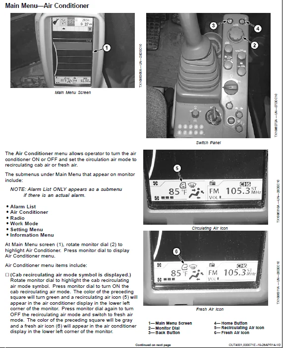
Main Menu—Air Conditioner 2-2-11
Main Menu—Radio2-2-13
Main Menu—Work Mode2-2-14
Main Menu—Setting Menu 2-2-15
Main Menu—Setting Menu—Date and Time2-2-16
Main Menu—Setting Menu—Attachment
Name Input2-2-16
Main Menu—Setting Menu—Auto Shutdown 2-2-17
Main Menu—Setting Menu—Auto
Exhaust Filter Cleaning 2-2-18
Main Menu—Setting Menu—Sub
Meter Selection 2-2-19
Main Menu—Setting Menu—Rear
View Camera Monitor2-2-20
Main Menu—Setting Menu—Display
Item Selection 2-2-21
Main Menu—Setting Menu—Brightness
Adjustment2-2-21
Main Menu—Setting Menu—Language 2-2-21
Main Menu—Setting Menu—Unit Selection 2-2-22
Main Menu—Setting Menu—Main
Menu Sequence Change 2-2-22
Main Menu—Information Menu 2-2-23
Main Menu—Information Menu—Operation2-2-24
Main Menu—Information
Menu—Maintenance 2-2-25
Main Menu—Information
Menu—Troubleshooting 2-2-25
Main Menu—Information Menu—Monitoring2-2-26
Operation—Operating the Machine
Before Starting Work 2-3-1
Operator’s Daily Machine Check
Before Starting 2-3-1
Engine Break-In Period 2-3-2
Starting Engine 2-3-3
Cold Weather Start Aid2-3-4
Cold Weather Warmup 2-3-5
Travel Pedals and Levers2-3-6
Exhaust Filter2-3-7
Exhaust Filter Parked Cleaning 2-3-9
Service ADVISOR™ Remote (SAR)
Software Delivery Process 2-3-10
Service ADVISOR™ Remote (SAR)
Operation 2-3-11
Locking the Hydraulic Coupler to the
Attachment—If Equipped 2-3-13
Unlocking the Hydraulic Coupler From
the Attachment—If Equipped 2-3-15
Control Lever Pattern Operation2-3-16
Mechanical Control Lever Pattern
Selector—If Equipped 2-3-17
Control Lever Pattern Conversion 2-3-18
Operating in Water and Mud 2-3-19
Page
Driving Up a Steep or Slippery Slope 2-3-19
Lifting 2-3-19
Lower Boom With Engine Stopped2-3-20
Parking the Machine2-3-21
Loading and Unloading for Transport 2-3-22
Towing Machine2-3-23
Lifting the Machine 2-3-23
Maintenance—Machine
Diesel Fuel3-1-1
Diesel Fuel Specifications 3-1-1
Lubricity of Diesel Fuel 3-1-2
Handling and Storing Diesel Fuel 3-1-2
Biodiesel Fuel 3-1-3
Testing Diesel Fuel 3-1-4
Fuel Filters3-1-4
Minimizing the Effect of Cold Weather
on Diesel Engines 3-1-5
Alternative and Synthetic Lubricants 3-1-6
Mixing of Lubricants3-1-6
Lubricant Storage 3-1-6
John Deere Break-In Plus™ Engine Oil 3-1-7
Diesel Engine Oil—Interim Tier 4 and
Stage III B Engines 3-1-8
Engine Oil and Filter Service Intervals
— Interim Tier 4, Final Tier 4, Stage
IIIB, and Stage IV Engines 3-1-9
Oil Filters 3-1-9
Hydraulic Oil 3-1-10
Swing Gear Case and Travel Gear
Case Oils3-1-11
Pump Drive Gear Case Oil 3-1-11
Track Adjuster, Working Tool Pivot,
Swing Bearing, and Swing Bearing
Gear Grease 3-1-12
Diesel Engine Coolant (engine with
wet sleeve cylinder liners) 3-1-13
Drain Intervals for Diesel Engine Coolant3-1-14
John Deere COOL-GARD™ II Coolant
Extender3-1-14
Supplemental Coolant Additives3-1-15
Operating in Warm Temperature Climates 3-1-15
Additional Information About Diesel
Engine Coolants and John Deere
COOL-GARD™ II Coolant Extender 3-1-16
Testing Diesel Engine Coolant3-1-17
Disposing of Coolant 3-1-17
Maintenance—Periodic Maintenance
Service Machine at Specified Intervals3-2-1
Check the Hour Meter Regularly 3-2-1
Prepare Machine for Maintenance 3-2-2
Open Access Doors for Service 3-2-3
Open Engine Cover for Service3-2-3
Fuel Tank 3-2-3
Hydraulic Breaker and Crusher Attachments 3-2-4
Continued on next page
Fluid Analysis Program Test Kits and
3-Way Coolant Test Kit3-2-4
Service Intervals 3-2-5
Required Parts3-2-7
Maintenance—As Required
Remove and Clean Fuel Tank Inlet Screen 3-3-1
Check Windshield Washer Fluid Level 3-3-1
Check and Clean Air Cleaner Dust
Unloader Valve3-3-1
Check and Adjust Track Sag 3-3-2
Clean Rear Camera Lens—If Equipped 3-3-3
Check Coolant 3-3-4
Service Exhaust Filter3-3-5
Maintenance—10 Hours or Daily
Check Engine Oil Level 3-4-1
Check Engine Coolant Level 3-4-2
Check Hydraulic Tank Oil Level3-4-3
Lubricate Hydraulic Coupler—If Equipped 3-4-4
Maintenance—Every 50 Hours or Weekly
Drain Water and Sediment from Fuel
Tank Sump 3-5-1
Drain Primary Fuel Filter and Water Separator 3-5-1
Drain Final Fuel Filter 3-5-2
Drain Auxiliary Fuel Filter and Water
Separator—If Equipped3-5-2
Maintenance—Every 100 Hours
Lubricate Working Tool Pivots 3-6-1
Inspect and Re-Torque Track Hardware3-6-2
Maintenance—Every 250 Hours
Check Swing Gear Case Oil Level 3-7-1
Drain Water and Sediment from
Hydraulic Tank3-7-2
Check Pump Drive Gear Case Oil Level 3-7-3
Check Battery Electrolyte Level and Terminals 3-7-4
Check Travel Gear Case Oil Level 3-7-6
Take Engine Oil Sample 3-7-6
Maintenance—Every 500 Hours
Lubricate Front End Pin Joints 3-8-1
Lubricate Swing Bearing3-8-2
Lubricate Swing Bearing Gear3-8-2
Replace Primary Fuel Filter and Water
Separator 3-8-3
Replace Final Fuel Filter3-8-4
Replace Auxiliary Fuel Filter and Water
Separator—If Equipped3-8-5
Check Air Intake Hoses 3-8-5
Drain and Refill Engine Oil and Replace Filter 3-8-6
Clean Cab Fresh Air and Cab
Recirculating Air Filters 3-8-7
Take Fluid Samples 3-8-7
Page
Maintenance—Every 1000 Hours
Drain and Refill Swing Gear Case Oil 3-9-1
Replace Hydraulic Tank Oil Filter 3-9-2
Replace Pilot Oil Filter 3-9-3
Drain and Refill Pump Drive Gear Case Oil 3-9-4
Remove and Clean Open Crankcase
Ventilation (OCV) Hose 3-9-4
Inspect Serpentine Belt 3-9-5
Replace Air Cleaner Elements 3-9-6
Replace Air Cleaner Dust Unloader Valve3-9-6
Check Coolant 3-9-7
Maintenance—Every 2000 Hours
Check and Adjust Engine Valve Lash3-10-1
Drain and Refill Travel Gear Case Oil 3-10-1
Replace Open Crankcase Ventilation
(OCV) Filter 3-10-1
Maintenance—Every 5000 Hours
Drain and Refill Hydraulic Tank Oil 3-11-1
Replace Hydraulic Tank Vent Cap Filter 3-11-3
Maintenance—Every 6000 Hours
Drain Cooling System3-12-1
Cooling System Fill and Deaeration
Procedure3-12-2
Miscellaneous—Machine
Bleed Fuel System 4-1-1
Clean Radiator, Oil Cooler, Charge Air
Cooler, and Fuel Cooler 4-1-1
Do Not Service or Adjust Injection
Nozzles or High-Pressure Fuel Pump4-1-2
Do Not Service Control Valves,
Cylinders, Pumps, or Motors4-1-2
Precautions for Alternator and Regulator 4-1-2
Handling, Checking, and Servicing
Batteries Carefully4-1-3
Using Battery Charger 4-1-4
Using Booster Batteries—24-Volt System 4-1-5
Replacing Batteries 4-1-5
Fluid Sampling Test Ports—If Equipped 4-1-6
Welding On Machine 4-1-6
Clean the Machine Regularly 4-1-7
Adding 12—Volt Accessories 4-1-7
JDLink™ Machine Monitoring System
(MMS)—If Equipped4-1-7
Replacing Fuses4-1-8
Replacing Bucket Teeth4-1-11
Replacing Bucket Tooth
Tip—Heavy-Duty Bucket 4-1-13
Replacing Bucket Teeth—TK Series 4-1-13
Removing the Bucket 4-1-14
Track Sag General Information 4-1-14
Check Track Shoe Hardware 4-1-14
Continued on next page
Hardware Torque Specifications4-1-14
Unified Inch Bolt and Screw Torque Values4-1-15
Metric Bolt and Screw Torque Values4-1-16
Miscellaneous—Operational Checkout
Operational Checkout4-2-1
Miscellaneous—Troubleshooting
Troubleshooting Procedure 4-3-1
Engine 4-3-2
Hydraulic System4-3-5
Electrical System 4-3-7
Miscellaneous—Storage
Prepare Machine for Storage 4-4-1
Monthly Storage Procedure4-4-2
Miscellaneous—Machine Numbers
Record Product Identification Number (PIN) 4-5-1
Record Engine Serial Number4-5-1
Record Travel Motor Serial Numbers 4-5-2
Record Swing Motor Serial Number 4-5-2
Record Hydraulic Coupler Serial
Number—If Equipped4-5-3
Hydraulic Pump Serial Number 4-5-3
Keep Proof of Ownership 4-5-4
Keep Machines Secure 4-5-4
Miscellaneous—Specifications
160GLC Engine Specifications4-6-1
180GLC Engine Specifications4-6-1
160GLC and 180GLC Drain and Refill
Capacities 4-6-2
160GLC Machine Specifications 4-6-3
180GLC Machine Specifications 4-6-5
160GLC Working Ranges4-6-7
180GLC Working Ranges4-6-9
160GLC Lift Capacity—Arm: 260 m (8
ft 6 in); Bucket: 528 kg (1164 lb);
Shoe: 600 mm (24 in) 4-6-11
160GLC Lift Capacity—Arm: 260 m (8
ft 6 in); Bucket: 528 kg (1164 lb);
Shoe: 700 mm (28 in) 4-6-12
160GLC Lift Capacity—Arm: 310 m
(10 ft 2 in); Bucket: 528 kg (1164
lb); Shoe: 600 mm (24 in) 4-6-13
160GLC Lift Capacity—Arm: 310 m
(10 ft 2 in); Bucket: 528 kg (1164
lb); Shoe: 700 mm (28 in) 4-6-14
180GLC Lift Capacity—Arm: 271 m (8
ft 10 in); Bucket: 600 kg (1323 lb);
Shoe: 600 mm (24 in) 4-6-15
180GLC Lift Capacity—Arm: 271 m (8
ft 10 in); Bucket: 600 kg (1323 lb);
Shoe: 700 mm (28 in) 4-6-16
180GLC Lift Capacity—Arm: 271 m (8
ft 10 in); Bucket: 600 kg (1323 lb);
Shoe: 800 mm (32 in) 4-6-17
Page
180GLC Lift Capacity—Arm: 321 m
(10 ft 6 in); Bucket: 600 kg (1323
lb); Shoe: 600 mm (24 in) 4-6-18
180GLC Lift Capacity—Arm: 321 m
(10 ft 6 in); Bucket: 600 kg (1323
lb); Shoe: 700 mm (28 in) 4-6-19
180GLC Lift Capacity—Arm: 321 m
(10 ft 6 in); Bucket: 600 kg (1323
lb); Shoe: 800 mm (32 in) 4-6-20
iv
IMAGES PREVIEW OF THE MANUAL:
JOHN DEERE EXCAVATOR 160GLC AND 180GLC OPERATORS MANUAL – PDF DOWNLOAD:
https://vimeo.com/670232751
PLEASE NOTE:
- This is not a physical manual but a digital manual – meaning no physical copy will be couriered to you. The manual can be yours in the next 2 mins as once you make the payment, you will be directed to the download page IMMEDIATELY.
- This is the same manual used by the dealers inorder to diagnose your vehicle of its faults.
- Require some other service manual or have any queries: please WRITE to us at [email protected]
S.M