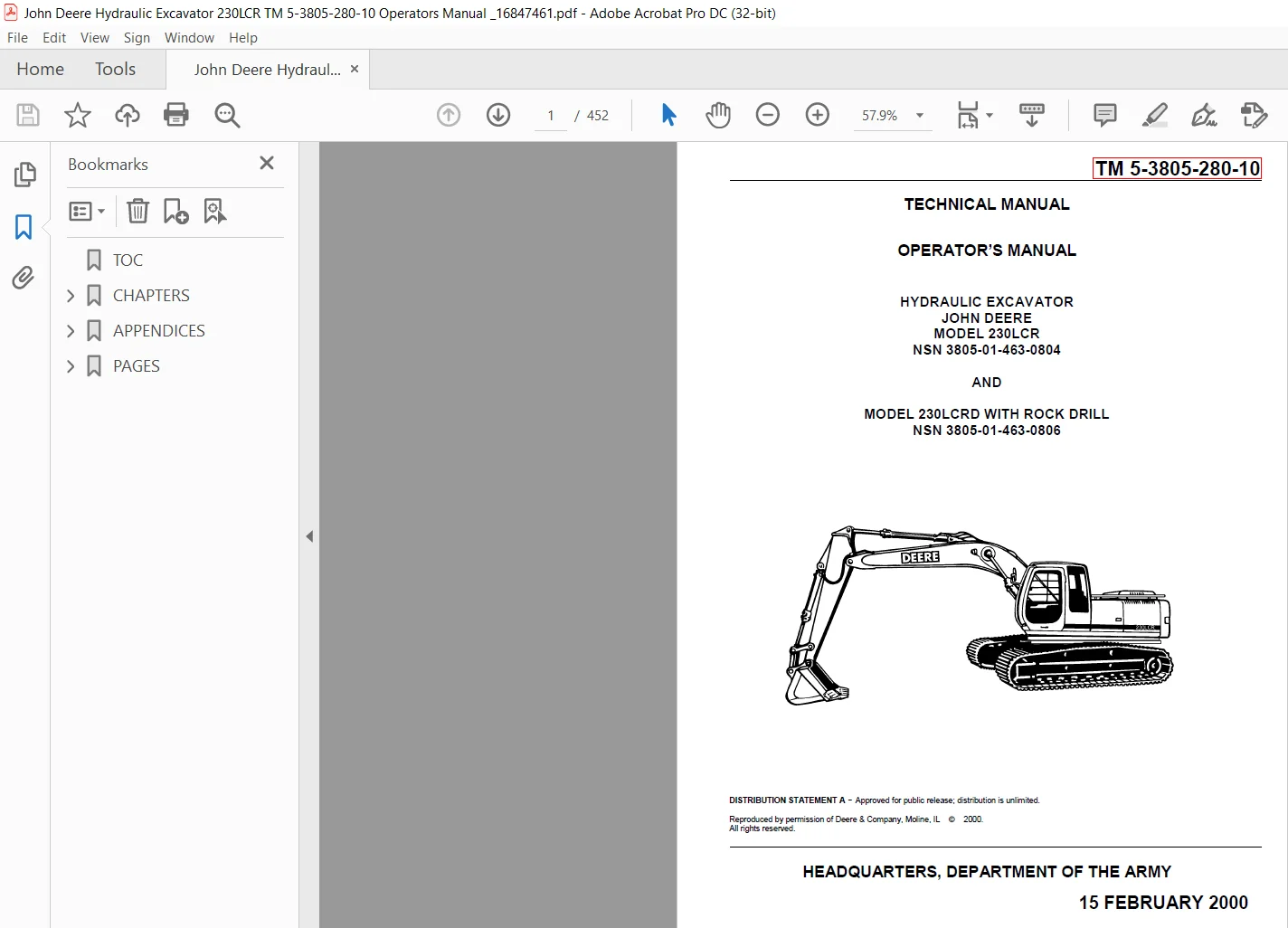
John Deere Hydraulic Excavator 230LCR TM 5-3805-280-10 Operators Manual – PDF DOWNLOAD
Original price was: $89.00.$29.95Current price is: $29.95.
John Deere Hydraulic Excavator 230LCR TM 5-3805-280-10 Operators Manual – PDF DOWNLOAD
Description
John Deere Hydraulic Excavator 230LCR TM 5-3805-280-10 Operators Manual – PDF DOWNLOAD
DESCRIPTION:
John Deere Hydraulic Excavator 230LCR TM 5-3805-280-10 Operators Manual – PDF DOWNLOAD
General.
This section explains the contractor’s warranty for the Hydraulic Excavator (HYEX), including all of its components and subassemblies. It also contains information, instructions, methods and forms required to obtain services and/or supplies and for processing claims for items covered under warranty for the HYEX.
If additional warranty information is required for the HYEX, contact your local Warranty Control Office/Officer (WARCO) or TACOM-WRN Logistics Assistance Representative (LAR). If your WARCO or TACOM LAR is not available, contact TACOM-WRN. The numbers at TACOM to call are DSN 786-7215/(810) 574-7215, DSN 786-7420/(810) 574-7420, or DSN 786-8297/(810) 574-8297.
The caller should be prepared to provide:
- name,
- telephone number and/or electronic address,
- complete unit designation,
- identification of the vehicle to include serial number(s) and
- a brief description of the problem.
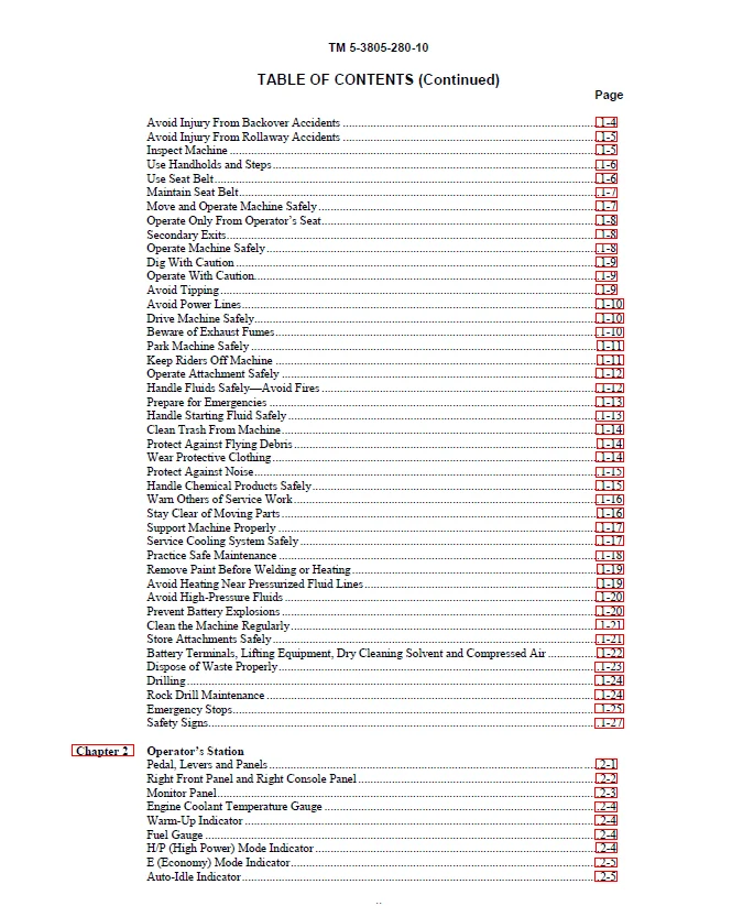
TABLE OF CONTENTS:
John Deere Hydraulic Excavator 230LCR TM 5-3805-280-10 Operators Manual – PDF DOWNLOAD
Avoid Injury From Backover Accidents 1-4
Avoid Injury From Rollaway Accidents 1-5
Inspect Machine 1-5
Use Handholds and Steps1-6
Use Seat Belt 1-6
Maintain Seat Belt1-7
Move and Operate Machine Safely 1-7
Operate Only From Operator’s Seat1-8
Secondary Exits1-8
Operate Machine Safely1-8
Dig With Caution 1-9
Operate With Caution1-9
Avoid Tipping 1-9
Avoid Power Lines1-10
Drive Machine Safely1-10
Beware of Exhaust Fumes1-10
Park Machine Safely 1-11
Keep Riders Off Machine 1-11
Operate Attachment Safely 1-12
Handle Fluids Safely—Avoid Fires 1-12
Prepare for Emergencies 1-13
Handle Starting Fluid Safely 1-13
Clean Trash From Machine1-14
Protect Against Flying Debris 1-14
Wear Protective Clothing1-14
Protect Against Noise1-15
Handle Chemical Products Safely1-15
Warn Others of Service Work1-16
Stay Clear of Moving Parts 1-16
Support Machine Properly 1-17
Service Cooling System Safely 1-17
Practice Safe Maintenance 1-18
Remove Paint Before Welding or Heating1-19
Avoid Heating Near Pressurized Fluid Lines 1-19
Avoid High-Pressure Fluids 1-20
Prevent Battery Explosions 1-20
Clean the Machine Regularly1-21
Store Attachments Safely1-21
Battery Terminals, Lifting Equipment, Dry Cleaning Solvent and Compressed Air 1-22
Dispose of Waste Properly1-23
Drilling 1-24
Rock Drill Maintenance 1-24
Emergency Stops1-25
Safety Signs1-27
Chapter 2 Operator’s Station
Pedal, Levers and Panels 2-1
Right Front Panel and Right Console Panel 2-2
Monitor Panel2-3
Engine Coolant Temperature Gauge 2-4
Warm-Up Indicator 2-4
Fuel Gauge 2-4
H/P (High Power) Mode Indicator 2-4
E (Economy) Mode Indicator2-5
Auto-Idle Indicator 2-5
TM 5-3805-280-10
TABLE OF CONTENTS (Continued)
Page
iii
Hydraulic Oil Level Indicator 2-5
Hydraulic Oil Filter Restriction Indicator (Model 230LCRD)2-6
Fuel Level Indicator 2-6
Air Filter Restriction Indicator 2-6
Engine Coolant Temperature Indicator 2-7
Charge Air Temperature Indicator 2-7
Engine Oil Pressure Indicator2-8
Alternator Voltage Indicator 2-8
Engine Oil Level Indicator 2-8
Coolant Level Indicator2-9
Switch Panel2-10
Buzzer and Buzzer Stop Switch 2-11
Wiper Switch2-11
Washer Switch2-12
Operating Lights Switch2-12
Operating Rear Lights Switch2-13
Cab Light2-13
Overload Alarm and Indicator2-13
Key Switch2-14
Engine RPM Dial 2-14
Power Boost Switch 2-14
Horn 2-15
Hour Meter 2-15
Cab Heater and Air Conditioner2-16
Control Panel Switches 2-17
Cab Heater Operation2-18
Air Conditioner Operation2-18
Defroster Operation2-19
Front Console2-19
Operating the AM/FM Radio 2-20
Setting the Clock2-20
Cab Door Release Lever2-21
Secondary Exit Tool2-21
Opening Upper Front (Secondary Exit) Window2-21
Closing Upper Front Window2-22
Removing and Storing the Lower Front Window2-23
Opening Side Windows2-23
Opening and Closing the Roof Exit Cover2-24
Removing and Storing Fire Extinguisher (Model 230LCR) 2-24
Rock Drill Start—Stop Selection Control Box (Model 230LCRD) 2-25
Compressor Remote Instrument Control Panel (Model 230LCRD) 2-26
Removing and Storing Rifle2-26
J-Hooks 2-27
Toolbox Security Hasp2-27
Decontamination Kit Bracket 2-28
Vandal Protection Panel Storage2-28
Adjusting the Seat 2-29
Adjusting the Armrest 2-30
Seat Belt 2-30
Operator’s Manual Compartment2-30
Chapter 3 Break-In
Engine Break-In Oil 3-1
Every 4 Hours3-1
TM 5-3805-280-10
TABLE OF CONTENTS (Continued)
Page
iv
Every 10 Hours or Daily 3-2
After the First 50 Hours3-2
After the First 100 Hours3-3
Chapter 4 Pre-Start Inspection
Inspect Machine Daily Before Starting 4-1
Chapter 5 Operating the Engine
Check Instruments Before Starting 5-1
Level Check5-1
Starting the Engine 5-2
Using Booster Batteries—24 Volt System5-3
Slave Receptacle—24 Volt System5-4
Starting Fluid (Cold Weather Starting Aid) 5-5
Using the Arctic Starter5-7
Starting the Arctic Starter5-8
Check Instruments After Starting5-8
Warming the Machine5-9
Cold Weather Warm-Up 5-10
Stopping the Engine 5-11
Chapter 6 Driving the Machine
Steering the Machine Using Pedals6-1
Steering the Machine Using Levers 6-3
Removing Propel Levers 6-5
Propel Speed Switch6-6
Travel Alarm and Travel Alarm Cancel Switch6-6
Parking the Machine6-7
Parking Machine During Freezing Weather 6-8
Lock All Compartments 6-8
Chapter 7 Operating the Machine
Control Levers7-1
Control Lever Pattern Conversion7-3
Control Levers John Deere Pattern7-5
Pilot Control Shut-Off Lever7-6
Auto-Idle Switch 7-7
Mode Selection Switch7-8
Power Boost Switch 7-8
E (Economy) Mode 7-9
H/P (High Power) Mode 7-10
Standard Mode 7-10
Operating Tips7-11
Driving Machine 7-11
Driving on Slopes7-12
Driving Down a Slope7-12
Driving Up a Slope7-12
Driving Up a Steep or Slippery Slope—Boom on Uphill End of Machine7-13
Driving Up a Steep or Slippery Slope—Boom on Downhill End of Machine7-13
Moving Machine off an Embankment7-14
Leveling Machine7-15
Using Quick-Disconnect Hitch7-16
Two Way Hydraulic Thumb Foot Pedal (Model 230LCR)7-20
Using Hydraulic Thumb7-21
Using Bucket 7-23
TM 5-3805-280-10
TABLE OF CONTENTS (Continued)
Page
v
Planning Spoil Piles 7-25
Trenching 7-25
Backfilling7-27
Truck Loading7-28
Operating in Water and Mud7-29
Clean Track Frame Area 7-29
Lifting7-30
Air Compressor – Operating Instructions 7-32
Using Quick-Coupler Type Attachments 7-37
Rock Drill Attachment (Model 230LCRD)7-38
Install Rock Drill7-38
Remove Rock Drill7-41
Operating the Rock Drill Attachment7-43
Remote Control Operator’s Panel 7-43
Rod Changer7-45
Start Up 7-49
Travelling 7-50
Drilling 7-51
Shut Down7-53
Lower Boom With Engine Stopped 7-54
Using Hydraulic Hand Tools Hose Reel 7-55
Using Hydraulic Hand Tools Flow Rate Valve and Switch 7-55
Using Hand Held Air Tools7-55
Chapter 8 Transporting
Loading Machine on a Trailer 8-1
Tiedowns 8-2
Fasten Machine to Trailer 8-3
Loading and Fastening Rock Drill on a Trailer8-6
Fasten Machine to Rail Car (Model 230LCR) 8-8
Fasten Machine and Rock Drill to Rail Car (Model 230LCRD) 8-10
Unloading Machine From Trailer8-12
Towing Machine 8-13
Lifting the Machine8-14
Chapter 9 Fuels and Lubricants
Diesel Fuel 9-1
Lubricity of Diesel Fuels9-1
Low Sulfur Diesel Fuel Conditioner 9-2
Diesel Fuel Storage 9-2
Fuel Tank 9-3
Do Not Use Galvanized Containers 9-3
Diesel Engine and Pump Gearbox Oils 9-4
Hydraulic Oil9-5
Swing Gearbox and Propel Gearbox Oils9-6
Track Roller, Front Idler, and Carrier Roller Oil 9-6
Track Adjuster, Working Tool Pivot, Swing Bearing, and Swing Bearing Gear Grease 9-7
Oil Filters 9-7
Rock Drill Lubricants Specifications 9-8
Air Compressor Lubricants 9-10
Lubricant Storage 9-11
Alternative and Synthetic Lubricants 9-11
Mixing of Lubricants9-12
Factory/Initial Fill Lubricants 9-12
TM 5-3805-280-10
TABLE OF CONTENTS (Continued)
Page
vi
Chapter 10 Periodic Maintenance—Excavator
Service Your Machine at Specified Intervals 10-1
Check the Hour Meter Regularly 10-1
Use Correct Fuels and Lubricants 10-1
Prepare Machine for Maintenance10-2
Open Access Doors for Service10-3
Open Hood for Service10-4
Chapter 11 Maintenance—As Required
Sampling Engine Oil (GRP NO 0400) 11-1
Sampling Hydraulic Oil (GRP NO 3360) 11-2
Clean Fuel Tank Inlet Screen (GRP NO 0560) 11-3
Drain Fuel Tank Sump (GRP NO 0560) 11-3
Clean Radiator Air Inlet Screens (GRP NO 0511)11-4
Drain Water Separator (GRP NO 0560)11-4
Clean Air Cleaner Dust Unloader Valve (GRP NO 0521) 11-5
Check Track Sag (GRP NO 0132) 11-5
Adjusting Track Sag (GRP NO 0132)11-6
Windshield Washer Fluid Level11-7
Chapter 12 Maintenance—Every 10 Hours or Daily
Check Engine Oil Level (GRP NO 0400) 12-1
Check Recovery Tank Coolant Level (GRP NO 0510)12-2
Check Hydraulic Oil Level (GRP NO 3360) 12-3
Chapter 13 Maintenance—Every 50 Hours
Grease Working Tool Pivots (GRP NO 3302) 13-1
Chapter 14 Maintenance—Every 250 Hours
Check Swing Gearbox Oil Level (GRP NO 4351)14-1
Drain Hydraulic Tank Sump (GRP NO 3364) 14-1
Check Pump Drive Gearbox Oil Level (GRP NO 3361) 14-2
Change Engine Oil and Replace Filter (GRP NO 0407) 14-3
Check Radiator Coolant Level 14-5
Check Battery Electrolyte Level and Terminals (GRP NO 1671)14-6
Check Propel Gearbox Oil Level (GRP NO 0250) 14-8
Clean Dusty Primary Element (GRP NO 0521)14-9
Inspect Element (GRP NO 0521)14-10
Chapter 15 Maintenance—Every 500 Hours
Grease Swing Bearing (GRP NO 4353)15-1
Grease Swing Bearing Gear (GRP NO 4353) 15-2
Replace Final Fuel Filter (GRP NO 0420) 15-3
Replace Primary Fuel Filter (Water Separator) (GRP NO 0560)15-4
Check Air Intake Hoses (GRP NO 0521)15-5
Replace Hydraulic Oil Filter (GRP NO 3360) 15-6
Add Coolant Conditioner to Radiator (GRP NO 0510) 15-8
Chapter 16 Maintenance—Every 1000 Hours
Change Swing Gearbox Oil (GRP NO 4351)16-1
Change Pilot Control Oil Filter (GRP NO 3362) 16-1
Change Pump Drive Gearbox Oil (GRP NO 3360) 16-2
Clean the Engine Crankcase Ventilation Tube16-3
Check and Adjust Engine Valve Lash (Clearance) 16-3
Firing Order 6-Cylinder Engine 16-5
TM 5-3805-280-10
TABLE OF CONTENTS (Continued)
Page
vii
Check Engine Speeds 16-6
Engine Speed Learning Procedure 16-7
Change Air Cleaner Elements (GRP NO 0521) 16-7
Inspect Fan Belt (GRP NO 0429)16-8
Replace Air Cleaner Dust Valve (GRP NO 0521) 16-8
Chapter 17 Maintenance—Every 2000 Hours
Drain Cooling System (GRP NO 0510) 17-1
Diesel Engine Coolant (GRP NO 0510)17-2
Cooling System Fill and Deaeration Procedure (GRP NO 0510) 17-3
Change Propel Gearbox Oil 17-4
Change Hydraulic Oil17-5
Chapter 18 Maintenance—Air Compressor
General 18-1
Scheduled Maintenance18-1
Compressor Oil Maintenance18-1
Air Cleaner 18-2
Gauges18-3
Fuel Tank 18-3
Battery18-3
Automatic Shutdown System18-3
Compressor Oil Cooler18-4
Radiator 18-4
Hoses 18-4
Compressor Oil Filters 18-5
Fasteners18-6
Compressor Oil 18-6
Receiver-Separator Systems18-6
Scavenge Line 18-6
Cooling Fan Drive18-6
Oil Separator Element 18-7
Exterior Finish Care 18-8
Lubrication 18-10
Chapter 19 Maintenance—Rock Drill Attachment
First Oil Change 19-1
When Required19-3
Adjustment of Drilling Automatisms 19-4
Replacing Rock Drill Dust Collector Filters 19-8
Daily Maintenance Hydraulic Dust Collector 19-9
Daily19-10
Every 50 Hours19-10
Every 1000 Hours19-11
Every 2000 Hours19-11
Drifter Maintenance 19-12
Chapter 20 Maintenance
Do Not Service Injection Nozzles 20-1
Do Not Change Injection Pump 20-1
Bleeding the Fuel System20-2
Precautions for Alternator and Regulator20-2
Service Batteries Carefully20-3
Checking Electrolyte Specific Gravity20-5
Using Battery Charger20-6
TM 5-3805-280-10
TABLE OF CONTENTS (Continued)
Page
viii
Replacing Batteries (GRP NO 1671) 20-7
Removing Batteries (GRP NO 1671) 20-7
Welding on Machine 20-8
Adding 12-Volt Accessories 20-9
Replacing Fuses20-9
Fuse (Blade-Type) Color Codes20-11
Checking Travel Alarm System (GRP NO 1671) 20-11
Replacing Bucket Teeth (GRP NO 3302) 20-12
Removing the Bucket (GRP NO 3302)20-13
Replacing Bucket Tooth Tip—Heavy-Duty Bucket (GRP NO 3302) 20-14
Do Not Service Control Valves, Cylinders, Pumps or Motors20-14
Track Sag General Information 20-15
Hardware Torque Specifications 20-15
Check Track Shoe Torque20-16
Unified Inch Bolt and Cap Screw Torque Values 20-17
Metric Bolt and Cap Screw Torque Values20-18
Additional Metric Cap Screw Torque Values 20-19
Check Oil Lines and Fittings20-20
Service Recommendations for O-Ring Boss Fittings20-21
Service Recommendations for Flat Face O-Ring Seal Fittings 20-23
Service Recommendations for 37° Flare and 30° Cone Seat Connectors 20-24
Service Recommendations for Flared Connections—Straight or Tapered Threads 20-25
Service Recommendations for Inch Series Four Bolt Flange Fittings20-26
Service Recommendations for Metric Series Four Bolt Flange Fitting20-28
Chapter 21 Operational Checkout
Operational Checkout21-1
Operator Station Checks—Key Switch On, Engine Off 21-2
Operator Station Checks—Engine On21-4
Hydraulic System Checks 21-8
Undercarriage Checks 21-15
Hydraulic Thumb Check 21-17
Quick-Disconnect Hitch Checks 21-17
Accessories Checks 21-18
Air Conditioning Checks21-20
Seat, Doors, Windows, Latches, and Locks Checks21-23
Coolant Checks 21-29
Chapter 22 Troubleshooting
Using Troubleshooting Charts22-1
Engine 22-2
Electrical System22-8
Hydraulic System22-14
Chapter 23 Storage
Prepare Machine for Storage23-1
Quick-Disconnect Hitch Storage Procedure23-2
Monthly Storage Procedure 23-3
Chapter 24 Specifications
230LCR/LCRD 24-1
230LCR/LCRD Working Ranges24-3
230LCR/LCRD 24-4
230LCR/LCRD Drain and Refill Capacities 24-5
TM 5-3805-280-10
TABLE OF CONTENTS (Continued)
230LCR/LCRD Lift Capacity—KG (LB)24-6
Rock Drill Attachment – Technical Specifications24-7
Air Compressor General Data 24-8
Appendix A Operator Preventive Maintenance Checks and Services (PMCS) A-1
Appendix B Components of End Item and Basic Issue Items List B-1
Appendix C References C-1
IMAGES PREVIEW OF THE MANUAL:
Contact us: [email protected]
JOHN DEERE HYDRAULIC EXCAVATOR 230LCR TM 5-3805-280-10 OPERATORS MANUAL – PDF DOWNLOAD:
PLEASE NOTE:
- This is the SAME MANUAL used by the dealerships to diagnose your vehicle
- No waiting for couriers / posts as this is a PDF manual and you can download it within 2 minutes time once you make the payment.
- Your payment is all safe and the delivery of the manual is INSTANT – You will be taken to the DOWNLOAD PAGE.
- So have no hesitations whatsoever and write to us about any queries you may have : heydownloadss @gmail.com
S.M