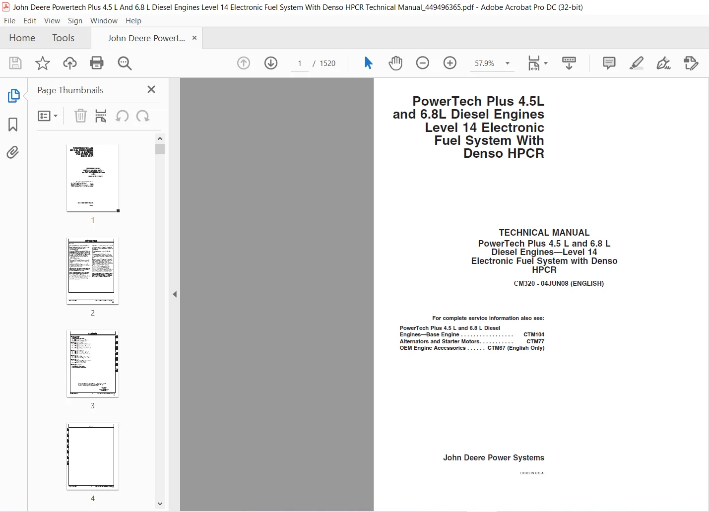
John Deere Powertech Plus 4.5 L & 6.8 L Diesel Engines Level 14 Electronic Fuel System With Denso HPCR Technical Manual
Original price was: $76.95.$38.95Current price is: $38.95.
John Deere Powertech Plus 4.5 L & 6.8 L Diesel Engines Level 14 Electronic Fuel System With Denso HPCR Technical Manual – PDF DOWNLOAD
Description
John Deere Powertech Plus 4.5 L & 6.8 L Diesel Engines Level 14 Electronic Fuel System With Denso HPCR Technical Manual – PDF DOWNLOAD
DESCRIPTION:
John Deere Powertech Plus 4.5 L & 6.8 L Diesel Engines Level 14 Electronic Fuel System With Denso HPCR Technical Manual – PDF DOWNLOAD
For complete service information also see:
PowerTech Plus 4.5 L and 6.8 L Diesel
Engines—Base Engine . . . . . . . . . . . . . . . . . CTM104
Alternators and Starter Motors. . . . . . . . . . . CTM77
OEM Engine Accessories . . . . . . CTM67 (English Only)
Forward :
This manual is written for an experienced technician. Essential tools required in performing certain service work are identified in this manual and are recommended for use. This manual (CTM320) covers only Level 14 Electronic Fuel System with the Denso High Pressure Common Rail (HPCR). It is one of six volumes on 4.5 L and 6.8 L engines. The following companion manual covers the base engine and mechanical fuel system. Each manual covers repair, operation, and diagnostics.
• CTM104—Base Engine
- Other manuals will be added in the future to provide additional information on electronic fuel systems as needed. Live with safety: Read the safety messages in the introduction of this manual and the cautions presented throughout the text of the manual. causym;This is the safety-alert symbol.
- When you see this symbol on the machine or in this manual, be alert to the potential for personal injury. Use this component technical manual in conjunction with the machine technical manual. An application listing in Section 01, Group 001 identifies product-model/component type-model relationship.
- See the machine technical manual for information on component removal and installation, and gaining access to the components. Information is organized in sections and groups for the various components requiring service instruction. At the beginning of each group are summaries of the up coming group.
- Before beginning repair on an engine, clean the engine. This manual contains SI Metric units of measure followed immediately by the U.S. customary units of measure. Most hardware on these engines are metric sized. Some components of this engine may be serviced without removing the engine from the machine.
- Refer to the specific machine technical manual for information on components that can be serviced without removing the engine from the machine and for engine removal and installation procedures. Read each block of material completely before performing service to check for differences in procedures or specifications.
- Follow only the procedures that apply to the engine model number you are working on. If only one procedure is given, that procedure applies to all the engines in the manual. CALIFORNIA PROPOSITION 65 WARNING: Diesel engine exhaust and some of its constituents are known to the State of California to cause cancer, birth defects, and other reproductive harm.
TABLE OF CONTENTS:
John Deere Powertech Plus 4.5 L & 6.8 L Diesel Engines Level 14 Electronic Fuel System With Denso HPCR Technical Manual – PDF DOWNLOAD
Contents 3
General 5
Safety 7
Work In Ventilated Area 7
Recognize Safety Information 7
Work in Clean Area 7
Dispose of Waste Properly 8
Avoid Harmful Asbestos Dust 8
Handle Fuel Safely—Avoid Fires 9
Prepare for Emergencies 9
Handle Starting Fluid Safely 9
Handle Fluids Safely—Avoid Fires 10
Avoid High-Pressure Fluids 10
Use Proper Lifting Equipment 11
Illuminate Work Area Safely 11
Live With Safety 11
Service Machines Safely 11
Handle Chemical Products Safely 12
Protect Against Noise 12
Remove Paint Before Welding or Heating 13
Stay Clear of Rotating Drivelines 13
Service Cooling System Safely 14
Follow Safety Instructions 14
Use Proper Tools 15
Construct Dealer-Made Tools Safely 15
Practice Safe Maintenance 16
Understand Signal Words 16
Replace Safety Signs 17
Prevent Battery Explosions 17
Protect Against High Pressure Spray 17
Avoid Heating Near Pressurized Fluid Lines 18
Wear Protective Clothing 18
Wait Before Opening High-Pressure Fuel System 18
Handle Agricultural Chemicals Safely 19
Handling Batteries Safely 20
Install Fan Guards 21
Avoid Hot Parts 21
Engine Identification 23
Engine Serial Number Plate Information 23
OEM Engine Option Code Label 25
Information Relative to Emissions Regulations 25
Emissions Control System Certification Label 26
Engine Application Charts 27
Fuels, Lubricants, and Coolant 29
Diesel Fuel 29
Biodiesel Fuel 30
Minimizing the Effect of Cold Weather on Diesel Engines 32
Handling and Storing Diesel Fuel 33
Lubricity of Diesel Fuel 34
Testing Diesel Fuel 34
Diesel Engine Oil 35
Diesel Engine Break-In Oil 36
Oil Filters 36
Grease 37
Alternative and Synthetic Lubricants 37
Lubricant Storage 38
Mixing of Lubricants 38
Diesel Engine Coolant 39
Supplemental Coolant Additives 40
Operating in Warm Temperature Climates 41
Additional Information About Diesel Engine Coolants and Supplemental Coolant Additives 42
Diesel Engine Coolant 43
Testing Diesel Engine Coolant 44
Drain Intervals for Diesel Engine Coolant 44
Engine Oil and Filter Service Intervals 44
Fuel System Identification 45
Low Pressure Fuel System Type 1 45
Low Pressure Fuel System Type 2 45
Low Pressure Fuel System Type 3 46
High Pressure Fuel System Type 1 46
High Pressure Fuel System Type 2 47
Fuel Dosing System Type 1 47
Repair and Adjustments 49
Electronic Fuel System Repair and Adjustments 51
Fuel System – General Information 51
Fuel System Components 52
Relieve Fuel System Pressure 53
Remove and Install Fuel Filter Base 54
Remove and Install Doser Header 55
Replace Fuel Filter Elements 57
Replacing Fuel Filter and Dosing Elements (4045) 59
Replacing Fuel Filter and Dosing Elements (6068) 62
Replace Fuel Filter Elements – Racor Fuel Filter System 65
Remove Fuel Transfer Pump 67
Install Fuel Transfer Pump 68
Remove and Install Electronic Fuel Transfer Pump – Filter Mounted 69
Remove and Install Electronic Fuel Transfer Pump – Racor System 70
Type 1 Remove and Install High Pressure Fuel Pump 72
Type 2 Remove and Install High Pressure Fuel Pump 75
Remove and Install High Pressure Common Rail 79
Remove and Install Flow Dampers 81
Remove and Install Pressure Limiter 83
Remove and Install Fuel Injection Wire Harness Assembly 85
Remove Electronic Injectors (EIs) 89
Clean Electronic Injector (EI) Bore 91
Clean Electronic Injector (EI) Orifice 91
Clean Electronic Injector (EI) Body 91
Inspect Electronic Injector (EI) Body 91
Install Electronic Injectors (EIs) 92
Remove and Install Leak-off and Pump Overflow Lines 95
Remove and Install Suction Control Valve 97
Electronic Air System Repair and Adjustment 103
Remove and Install Exhaust Gas Recirculation (EGR) Valve 103
Remove and Install EGR Exhaust Tube 104
Remove and Install EGR Coolant Inlet Tube 105
Remove and Install Exhaust Gas Recirculation (EGR) Cooler 106
Remove and Install Exhaust Gas Recirculation (EGR) Tubing 107
Remove and Install Variable Geometry Turbocharger Actuator (4-Cylinder Engine – If Equipped) 109
Remove and Install Variable Geometry Turbocharger Actuator (6-Cylinder Engine – If Equipped) 114
Remove and Install Turbocharger Actuator Linkage (6-Cylinder Engine) 116
Electronic Engine Control Repair and Adjustment 121
Engine Control Unit (ECU) Maintenance 121
Remove and Install Engine Control Unit (ECU) for 45L Engine 122
Remove and Install Engine Control Unit (ECU) for 68L Engine 125
Remove and Install Engine Coolant Temperature (ECT) Sensor 128
Remove and Install Fuel Temperature Sensor 128
Remove and Install Exhaust Gas Recirculation (EGR) Exhaust Temperature Sensor 129
Charge Air Cooler Outlet Temperature Sensor 129
Remove and Install Manifold Air Temperature (MAT) Sensor 130
Remove and Install Oil Pressure Sensor 130
Remove and Install Fuel Rail Pressure Sensor 131
Remove and Install Fuel Transfer Pump Pressure Sensor 132
Remove and Install Manifold Air Pressure (MAP) Sensor 133
Remove and Install Crank Position Sensor 133
Remove and Install Pump Position Sensor 134
Remove and Install Turbo Speed Sensor 134
Remove and Install Turbo Compressor Inlet Temperature Sensor 135
Remove and Install Water in Fuel (WIF) Sensor 135
Remove and Install Glow Plugs 136
ECU Wiring Harness Routing for 45L Engine 137
Remove and Install Engine Wire Harness for 45L Engine 138
ECU Wiring Harness Routing for 68L Engine 145
Remove and Install Engine Wire Harness for 68L Engine 146
Connectors 152
Connector Repair 153
Welding 154
High Pressure Washing 155
Repair WEATHERPACK™ Connector 156
Repair Cinch Flex Box Connector 159
Repair METRI-PACK Connectors(Push Type) 168
Repair DT Series Deutsch Connectors 169
Repair HD Series Deutsch Connectors 173
Theory Of Operation 177
Electronic Fuel System Operation 179
About This Group 179
Fuel System Operation 180
Prefilter Operation 181
Mechanical Fuel Transfer Pump Operation 182
Electric Fuel Transfer Pump Operation (Stanadyne) 183
Electric Fuel Transfer Pump Operation (Racor) 184
Final Fuel Filter Operation 185
Doser Operation 186
Type 1 High Pressure Fuel Pump Operation 187
Type 2 High Pressure Fuel Pump Operation 188
High Pressure Common Rail (HPCR) Operation 189
Electronic Injector (EI) Operation 190
Electronic Air System Operation 193
About This Group 193
Electronic Air System Control Operation 194
Exhaust Gas Recirculation Flow and Calculations 197
Exhaust Gas Recirculation Cooler 198
Exhaust Gas Recirculation Valve 199
Turbocharger 200
Turbocharger Actuator 201
Air Intake Manifold, non-EGR engines 202
Electronic Control System Operation 203
About This Group 203
Electronic Control System Terminology 204
Electronic Control Unit (ECU) System Operation 206
Component Location Diagram 1 209
Component Location Diagram 2 210
Component Location Diagram 3 212
Component Location Diagram 4 214
Component Location Diagram 5 215
Component Location Diagram 6 216
Component Location Diagram 7 217
Component Location Diagram 8 218
Component Location Diagram 9 219
Component Location Diagram 10 221
Component Location Diagram 11 222
Component Location Diagram 12 224
Component Location Diagram 13 225
Component Location Diagram 14 226
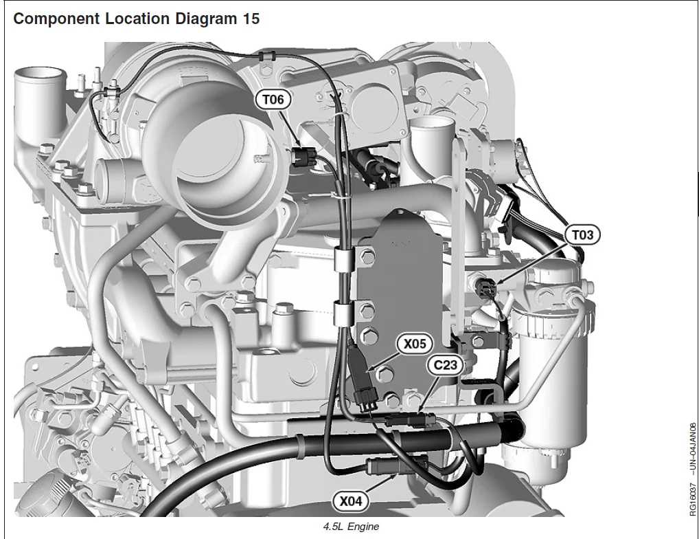
Component Location Diagram 15 227
Component Location Diagram 16 228
Component Location Diagram 17 229
Component Location Diagram 18 230
Component Location Diagram 19 231
Controller Area Network (CAN) 232
Monitoring Engine Parameters 233
Measuring Temperature 234
Engine Control Unit (ECU) Temperature Sensor 234
Engine Coolant Temperature (ECT) Sensor 235
Fuel Temperature Sensor 235
Exhaust Gas Recirculation (EGR) Exhaust Temperature Sensor 236
Charge Air Cooler Outlet Air Temperature Sensor 237
Intake Manifold Air Temperature (MAT) Sensor 238
Turbo Compressor Inlet Temperature Sensor 239
Turbo Turbine Inlet Temperature 240
Measuring Pressure 241
Barometric Air Pressure (BAP) Sensor 241
Fuel Rail Pressure Sensor 242
Fuel Transfer Pump Pressure Sensor 242
Manifold Air Pressure (MAP) Sensor 243
Oil Pressure Sensor 243
Measuring Speed 244
Crank Position Sensor 244
Pump Position Sensor 245
Turbo Speed Sensor 245
Throttle Descriptions 245
CAN Throttle 246
Pulse-Width-Modulated (PWM) Throttle 247
Analog Throttle 247
Digital Multi-State Throttle 247
Dual-State Throttle 248
Tri-State Throttle 249
Ramp Throttle 250
Throttle Adjustments 252
Throttle Offsets 253
Self-Calibration 254
Combination Throttle 255
Marine Throttle 256
Engine Derate and Shutdown Protection 258
Electronic Injector (EI) Wiring Harness Connector 259
Glow Plug Operation 260
Torque Curve Selection 261
Governor Droop Mode Selection 261
Suction Control Valve 262
Water in Fuel (WIF) Sensor 262
Engine Coolant Level Switch 262
Cruise Control Operation 263
Power Supply #1 263
Power Supply #2 264
Power Supply #3 264
Power Supply #4 265
Power Supply #5 265
Diagnostics 267
Observable Diagnostics and Tests 277
About This Group 277
E1 – Engine Cranks/Won’t Start 278
E1 – Engine Cranks/Won’t Start Diagnostic Procedure 278
E2 – Engine Misfires – Runs Irregularly 284
E2 – Engine Misfires/Runs Irregularly Diagnostic Procedure 284
E3 – Engine Does Not Develop Full Power 288
E3 – Engine Does Not Develop Full Power Diagnostic Procedure 288
E7 – Engine Idles Poorly 307
E7 – Engine Idles Poorly Diagnostic Procedure 307
E8 – Abnormal Engine Noise 310
E9 – Primary Analog Throttle Does Not Respond 313
E9 – Primary Analog Throttle Does Not Respond 313
E10 – Secondary Analog Throttle Does Not Respond 315
E10 – Secondary Analog Throttle Does Not Respond 315
F1 – Low Pressure Fuel Supply System Test 318
F1 ł Low Pressure Fuel Supply System Test Diagnostic Procedure 318
F2 – High Pressure Fuel Supply System Test 336
F2 – High Pressure Fuel Supply System Test Diagnostic Procedure 337
F3 – Excessive Fuel Consumption 349
F4 – Fuel in Oil 351
F4 – Fuel in Oil Diagnostic Procedure 351
D1 – ECU Does Not Communicate with Service ADVISOR 353
D1 – ECU Does Not Communicate with Service ADVISOR Diagnostic Procedure 353
D2 – ECU Does Not Communicate with Diagnostic Gauge or Gauge Displays CAN Bus Error 361
D2 – ECU Does Not Communicate with Diagnostic Gauge or Gauge Displays CAN Bus Error Diagnostic Procedure 361
D5 – ECU Does Not Program with Service ADVISOR 364
D5 – ECU Does Not Program with Service ADVISOR Diagnostic Procedure 364
A2 – Glow Plug Check 366
A2 – Glow Plug Check Diagnostic Procedure 367
Check Fuel Supply Quality 372
Check Fuel Supply Quality Diagnostic Procedure 372
Test for Air in Fuel 376
Check for Restricted Fuel Leak-off Line 379
Bleed the Fuel System 381
Bleed the Fuel System 381
Check and Adjust High Pressure Fuel Pump Static Timing 384
Charge Air System 385
Charge Air System Diagnostic 385
Excessive Engine Crankcase Pressure (Blow-By) 387
Excessive Engine Crankcase Pressure (Blow-By) Diagnostic Procedure 388
Exhaust Gas Recirculation (EGR) System Diagnostic 391
Exhaust Gas Recirculation (EGR) System Diagnostic 391
Variable Geometry Turbocharger (VGT) Component Test 395
Variable Geometry Turbocharger (VGT) Component Test Diagnostic Procedure 395
Temperature Sensor Validity Test 398
Temperature Sensor Validity Test Diagnostic Procedure 398
EGR-VGT System Temperature and Flow Test 399
EGR-VGT System Temperature and Flow Test 399
Trouble Code Diagnostics and Tests 403
About This Group 403
Electrical Concepts 404
Using a Digital Multimeter 404
Electrical Circuit Malfunctions 405
Troubleshooting Circuit Malfunctions 408
Connecting to Service ADVISOR 412
Diagnostic Gauge Data Parameters Viewing Instructions 419
Diagnostic Gauge Active DTC Viewing Instructions 421
Diagnostic Gauge Stored DTC Viewing Instructions 424
Diagnostic Gauge Stored DTC Clearing Instructions 426
Service ADVISOR Data Parameter Description 428
Snapshot Instructions 433
Internal Data Monitor Instructions 434
Terminal Test 437
Cylinder Misfire Test Instructions 440
Cylinder Electronic Compression Test Instructions 441
Engine Test Instructions – Cylinder Cutout Test 442
Harness Diagnostic Mode Test 443
Exhaust Gas Recirculation Valve Calibration 444
Turbo Learn Value Reset Test 445
Downloading Electronic Injector Calibration Files 446
Electronic Injector Calibration 447
Payload File Downloading Instructions 448
Engine Control Unit (ECU) Reprogramming Instructions 449
Diagnostic Trouble Codes List 449
Diagnostic Trouble Code Designations 454
Failure Mode Indicator Designations 458
Intermittent DTC Diagnostics 461
Trim Options Information 462
Interactive Tests and Calibration Results Printing Instructions 463
Control Unit Information Gathering Interactive Test 465
Engine Hour Updating Instructions Using Service ADVISOR 466
00002803 — Digital Throttle Signal Out of Range High 467
00002803 — Digital Throttle Signal Out of Range High Diagnostic Procedure 468
00002804 — Digital Throttle Signal Out of Range Low 472
00002804 — Digital Throttle Signal Out of Range Low Diagnostic Procedure 473
00002903 — Secondary Analog Throttle Signal Out of Range High 478
00002903 — Secondary Analog Throttle Signal Out of Range High Diagnostic Procedure 479
00002904 — Secondary Analog Throttle Signal Out of Range Low 485
00002904 — Secondary Analog Throttle Signal Out of Range Low Diagnostic Procedure 486
00009103 — Primary Analog Throttle Signal Out of Range High 492
00009103 — Primary Analog Throttle Signal Out of Range High Diagnostic Procedure 493
00009104 — Primary Analog Throttle Signal Out of Range Low 499
00009104 — Primary Analog Throttle Signal Out of Range Low Diagnostic Procedure 500
00009109 — Throttle CAN message Missing 506
00009403 — Low Pressure Fuel Signal Out of Range High 507
00009403 — Low Pressure Fuel Signal Out of Range Low Diagnostic Procedure 508
00009404 — Low Pressure Fuel Signal Out of Range Low 514
00009404 — Low Pressure Fuel Signal Out of Range Low Diagnostic Procedure 515
00009417 — Low Pressure Fuel Signal Slightly Low 522
00009417 — Low Pressure Fuel Signal Slightly Low Procedure 523
00009703 — Water In Fuel Signal Out of Range High 527
00009703 — Water In Fuel Signal Out of Range High Diagnostic Procedure 528
00009704 — Water In Fuel Signal Out of Range Low 533
00009704 — Water In Fuel Signal Out of Range Low Diagnostic Procedure 534
00009716 — Water in Fuel Detected 540
00009716 — Water In Fuel Detected Diagnostic Procedure 541
00010001 — Engine Oil Pressure Signal Extremely Low 545
00010001 — Engine Oil Pressure Signal Extremely Low Diagnostic Procedure 546
00010004 — Engine Oil Pressure Signal Out of Range Low 550
00010004 — Engine Oil Pressure Signal Out of Range Low Diagnostic Procedure 551
00010018 — Engine Oil Pressure Signal Moderately Low 557
00010018 — Engine Oil Pressure Signal Moderately Low Diagnostic Procedure 558
00010031 — Engine Oil Pressure Detected with Engine Stopped 562
00010031 — Engine Oil Pressure Detected with Engine Stopped Diagnostic Procedure 563
00010202 — Manifold Air Pressure Signal Invalid 567
00010202 — Manifold Air Pressure Signal Invalid Diagnostic Procedure 568
00010203 — Manifold Air Pressure Signal Out of Range High 571
00010203 — Manifold Air Pressure Signal Out of Range High Diagnostic Procedure 572
00010204 — Manifold Air Pressure Signal Out of Range Low 578
00010204 — Manifold Air Pressure Signal Out of Range Low Diagnostic Procedure 579
00010300 — Turbo Speed Signal Extremely High 585
00010300 — Turbo Speed Signal Extremely High Diagnostic Procedure 586
00010305 — Turbo Speed Signal Circuit has High Resistance 591
00010305 — Turbo Speed Signal Circuit has High Resistance Diagnostic Procedure 592
00010308 — Turbo Speed Signal Invalid 596
00010308 — Turbo Speed Signal Invalid Diagnostic Procedure 597
00010331 — Turbo Speed Signal Missing 602
00010331 — Turbo Speed Signal Missing Diagnostic Procedure 603
00010500 — Manifold Air Temperature Signal Extremely High 608
00010500 — Manifold Air Temperature Signal Extremely High Diagnostic Procedure 609
00010503 — Manifold Air Temperature Signal Out of Range High 615
00010503 — Manifold Air Temperature Signal Out of Range High Diagnostic Procedure 616
00010504 — Manifold Air Temperature Signal Out of Range Low 622
00010504 — Manifold Air Temperature Signal Out of Range Low Diagnostic Procedure 623
00010515 — Manifold Air Temperature Signal Slightly High 629
00010515 — Manifold Air Temperature Signal Slightly High Diagnostic Procedure 630
00010516 — Manifold Air Temperature Signal Moderately High 635
00010516 — Manifold Air Temperature Signal Moderately High Diagnostic Procedure 636
00010700 — Air Filter Restriction Switch Activated 641
00010731 — Air Filter Restriction Switch Activated 642
00010731 — Air Filter Restriction Switch Activated Diagnostic Procedure 643
00010802 — Barometric Air Pressure Signal Invalid 649
00010802 — Barometric Air Pressure Signal Invalid Diagnostic Procedure 650
00011000 — Coolant Temperature Signal Extremely High 653
00011000 — Coolant Temperature Signal Extremely High Diagnostic Procedure 654
00011003 — Coolant Temperature Signal Out of Range High 659
00011003 — Coolant Temperature Signal Out of Range High Diagnostic Procedure 660
00011004 — Coolant Temperature Signal Out of Range Low 666
00011004 — Coolant Temperature Signal Out of Range Low Diagnostic Procedure 667
00011015 — Coolant Temperature Signal Slightly High 673
00011015 — Coolant Temperature Signal Slightly High Diagnostic Procedure 674
00011016 — Coolant Temperature Signal Moderately High 679
00011016 — Coolant Temperature Signal Moderately High Diagnostic Procedure 680
00011017 — Coolant Temperature Signal Slightly Low 685
00011017 — Coolant Temperature Signal Slightly Low Diagnostic Procedure 686
00011101 — Engine Coolant Level Extremely Low 691
00011101 — Engine Coolant Level Low Diagnostic Procedure 692
00015703 — Fuel Rail Pressure Signal Out of Range High 699
00015703 — Fuel Rail Pressure Signal Out of Range High Diagnostic Procedure 700
00015704 — Fuel Rail Pressure Signal Out of Range Low 709
00015704 — Fuel Rail Pressure Signal Out of Range Low Diagnostic Procedure 710
00015710 — Fuel Rail Pressure Loss Detected 716
00015710 — Fuel Rail Pressure Loss Detected Diagnostic Procedure 717
00015717 — Fuel Rail Pressure Not Developed 722
00015717 — Fuel Rail Pressure Not Developed Diagnostic Procedure 723
00015817 — ECU Power Down Error 727
00015817 — ECU Power Down Error Diagnostic Procedure 727
00017400 — Fuel Temperature Signal Extremely High 729
00017400 — Fuel Temperature Signal Extremely High Diagnostic Procedure 730
00017403 — Fuel Temperature Signal Out of Range High 736
00017403 — Fuel Temperature Signal Out of Range High Diagnostic Procedure 737
00017404 — Fuel Temperature Signal Out of Range Low 742
00017404 — Fuel Temperature Signal Out of Range Low Diagnostic Procedure 743
00017416 — Fuel Temperature Signal Moderately High 746
00017416 — Fuel Temperature Signal Moderately High Diagnostic Procedure 747
00018900 — Engine Speed Derate Condition Exists 752
00019000 — Engine Speed Extremely High 753
00019000 — Engine Speed Extremely High Diagnostic Procedure 753
00019016 — Engine Speed Moderately High 757
00019016 — Engine Speed Moderately High Diagnostic Procedure 757
00023702 — VIN Security Data Invalid 761
00023713 — VIN Option Code Security Data Conflict 762
00023731 — VIN Security Data Missing 763
00041200 — EGR Temperature Signal Extremely High 764
00041200 — EGR Temperature Signal Extremely High Diagnostic Procedure 765
00041203 — EGR Temperature Signal Out of Range High 771
00041203 —EGR Temperature Signal Out of Range High Diagnostic Procedure 772
00041204 — EGR Temperature Signal Out of Range Low 777
00041204 — EGR Temperature Signal Out of Range Low Diagnostic Procedure 778
00041215 — EGR Temperature Signal Slightly High 784
0041215 — EGR Temperature Signal Slighty High Diagnostic Procedure 785
00063705 — Crankshaft Position Sensor Circuit Has High Resistance 867
00063705 — Crankshaft Position Sensor Circuit Has High Resistance Diagnostic Procedure 868
00063706 — Crankshaft Position Circuit Has Low Resistance 872
00063706 — Crankshaft Position Circuit Has Low Resistance Diagnostic Procedure 873
00063707 — Crankshaft and Camshaft Position Signals Out of Sync 877
00063707 — Crankshaft and Camshaft Position Signals Out of Sync Diagnostic Procedure 878
00063708 — Crankshaft Position Signal Missing 884
00063708 — Crankshaft Position Signal Missing Diagnostic Procedure 885
00064104 — VGT Actuator Supply Voltage Out of Range Low 898
00064104 — VGT Actuator Supply Voltage Out of Range Low Diagnostic Procedure 899
00107506 — Low Pressure Fuel Pump Circuit Has Low Resistance1121
00107506 — Low Pressure Fuel Pump Circuit Has Low Resistance Diagnostic Procedure1122
00107512 — Low Pressure Fuel Pump Status Error1126
00107512 — Low Pressure Fuel Pump Status ErrorDiagnostic Procedure1127
00110931 — Approaching Engine Protection Shutdown1133
00110931 — Approaching Engine Protection Shutdown Diagnostic Procedure1133
00111031 — Engine Protection Shutdown Active1135
00111031 — Engine Protection Shutdown Active Diagnostic Procedure1135
00113600 — ECU Temperature Signal Extremely High1137
00113600 — ECU Temperature Signal Extremely High Diagnostic Procedure1138
00113616 — ECU Temperature Signal Moderately High1142
00113616 — ECU Temperature Signal Moderately High Diagnostic Procedure1143
00117203 — Compressor Inlet Temperature Signal Out of Range High1147
00117203 — Compressor Inlet Temperature Signal Out of Range High Diagnostic Procedure1148
00117204 — Compressor Inlet Temperature Signal Out of Range Low1153
00117204 — Compressor Inlet Temperature Signal Out of Range Low Diagnostic Procedure1154
00118000 — Calculated Turbine Inlet Temperature Signal Extremely High1160
00118000 — Calculated Turbine Inlet Temperature Signal Extremely High Diagnostic Procedure1161
00118016 — Calculated Turbine Inlet Temperature Signal Moderately High1170
00118016 — Calculated Turbine Inlet Temperature Signal Moderately High Diagnostic Procedure1171
00134703 — Suction Control Valve Signal Out of Range High1180
00134703 — Suction Control Valve Signal Out of Range High Diagnostic Procedure1181
00134705 — Suction Control Valve Circuit Has High Resistance1185
00134705 — Suction Control Valve Circuit Has High Resistance Diagnostic Procedure1186
00134707 — Fuel Rail Pressure Actual to Desired Mismatch1191
00134707 — Fuel Rail Pressure Actual to Desired Mismatch Diagnostic Procedure1192
00156931 — Engine in Power Derate Condition1196
00163800 — Hydraulic Oil Temperature Extremely High1197
00163803 — Hydraulic Oil Temperature Signal Out of Range High1198
00163804 — Hydraulic Oil Temperature Signal Out of Range Low1199
00163816 — Hydraulic Oil Temperature Signal Moderately High1200
00163901 — Fan Speed Signal Extremely Low 1201
00163916 — Fan Speed Signal Moderately High1202
00163918 — Fan Speed Signal Moderately Low1203
00200013 — Incorrect ECU for Application1204
00200509 — No CAN Message From Source Address 51205
00200514 — Incorrect CAN Message Received From Source Address 51206
00200514 — Incorrect CAN Message Received From Source Address 5 Diagnostic Procedure1206
1206
00203009 — No CAN Message From Source Address 231207
00207109 — No CAN Message From Source Address 711208
00258003 — Brake Pressure Signal Out of Range High1209
00258004 — Brake Pressure Signal Out of Range Low1210
00263000 — Charge Air Cooler Outlet Temperature Signal Extremely High1211
00263000 – Charge Air Cooler Outlet Temperature Signal Extremely High Diagnostic Procedure1212
00263003 — Charge Air Cooler Outlet Temperature Signal Out of Range High1217
00263003 — Charge Air Cooler Outlet Temperature Signal Out of Range High Diagnostic Procedure1218
00263004 — Charge Air Cooler Outlet Temperature Signal Out of Range Low1223
00263004 — Charge Air Cooler Outlet Temperature Signal Out of Range Low Diagnostic Procedure1224
00263015 — Charge Air Cooler Outlet Temperature Signal Slightly High1230
00263015 — Charge Air Cooler Outlet Temperature Signal Slightly High Diagnostic Procedure1231
00263016 — Charge Air Cooler Outlet Temperature Signal Moderately High1236
00263016 — Charge Air Cooler Outlet Temperature Signal Moderately High Diagnostic Procedure1237
00265902 — Calculated EGR Flow Rate Invalid1242
00265902 — Calculated EGR Flow Rate Invalid Diagnostic Procedure1243
00265915 — Calculated EGR Flow Rate Slightly High1253
00265915 — Calculated EGR Flow Rate Slightly High Diagnostic Procedure1254
00265917 — Calculated EGR Flow Rate Slightly Low1263
00265917 — Calculated EGR Flow Rate Slightly Low Diagnostic Procedure1264
00279016 — Calculated Compressor Outlet Temperature Moderately High1274
00279016 — Calculated Compressor Outlet Temperature Moderately High1275
00279102 — EGR Valve Position Signal Invalid1282
00279102 – EGR Valve Position Signal Invalid Diagnostic Procedure1283
00279103 — EGR Valve Position Signal Out of Range High1289
00279103 — EGR Valve Position Signal Out of Range High Diagnostic Procedure1290
00279104 — EGR Valve Position Signal Out of Range Low1298
00279104 — EGR Valve Position Signal Out of Range Low Diagnostic Procedure1299
00279107 — EGR Valve Not Reaching Expected Position1305
00279107 – EGR Valve Not Reaching Expected Position Diagnostic Procedure1306
00279113 — EGR Valve Calibration Change Over a Short Period of Time1313
00279113 — EGR Valve Calibration Change Over a Short Period of Time Diagnostic Procedure1314
00279131 — EGR Valve Calibration Change over a Long Time1320
00279131 — EGR Valve Calibration Change over a Long Time Diagnostic Procedure1321
00279507 — VGT Actuator Not Reaching Expected Position1327
00279507 — VGT Actuator Not Reaching Expected Position Diagnostic Procedure1328
00350903 — Sensor Supply #1 Voltage Out of Range High1332
00350903 — Sensor Supply #1 Voltage Out of Range High Diagnostic Procedure1333
00350904 — Sensor Supply #1 Voltage Out of Range Low1337
00350904 — Sensor Supply #1 Voltage Out of Range Low Diagnostic Procedure1338
00351003 — Sensor Supply #2 Voltage Out of Range High1343
00351003 — Sensor Supply #2 Voltage Out of Range High Diagnostic Procedure1344
00351004 — Sensor Supply #2 Voltage Out of Range Low1348
00351004 — Sensor Supply #2 Voltage Out of Range Low Diagnostic Procedure1349
00351103 — Sensor Supply #3 Voltage Out of Range High1355
00351103 — Sensor Supply #3 Voltage Out of Range High Diagnostic Procedure1356
00351104 — Sensor Supply #3 Voltage Out of Range Low1360
00351104 — Sensor Supply #3 Voltage Out of Range Low Diagnostic Procedure1361
00351203 — Sensor Supply #4 Voltage Out of Range High1366
00351203 — Sensor Supply #4 Voltage Out of Range High Diagnostic Procedure1367
00351204 — Sensor Supply #4 Voltage Out of Range Low1371
00351204 — Sensor Supply #4 Voltage Out of Range Low Diagnostic Procedure1372
00351303 — Sensor Supply #5 Voltage Out of Range High1377
00351303 — Sensor Supply #5 Voltage Out of Range High Diagnostic Procedure1378
00351304 — Sensor Supply #5 Voltage Out of Range Low1382
00351304 — Sensor Supply #5 Voltage Out of Range Low Diagnostic Procedure1383
52379204 — EPGDS LTC Pump Signal Out of Range Low1388
52409911 — EPGDS LTC Pump Blockage1389
Tools1391
Electronic Fuel/Control System Repair Tools and Other Material1393
Repair and Adjustment Tools1393
Connector Repair Tools1397
Other Materials (Consumables)1400
Diagnostic Service Tools1401
Electronic System Diagnostic Tools1401
Specifications1405
Repair Specifications1407
Unified Inch Bolt and Cap Screw Torque Values1407
Metric Bolt and Cap Screw Torque Values1408
Electronic Air system Repair and Adjustment Specifications1409
Electronic Fuel System Repair and Adjustment Specifications1410
Electronic Engine Control Repair and Adjustment Specifications1412
Diagnostic Specifications1413
Fuel System Diagnostic Specifications1413
Application Specifications1415
OEM Engines – Derate Specifications1416
OEM Engines – Glow Plug Specifications1419
EGR Temperature Sensor Characteristics1420
Compressor Inlet Air Temperature Sensor Characteristics1421
Manifold Air Temperature Sensor and Charged Air Cooler Outlet Temperature Sensor Characteristics1422
45L 12V ECU Wiring Diagram 11423
45L 12V ECU Wiring Diagram 21425
45L 12V ECU Wiring Diagram 31427
45L 12V ECU Wiring Diagram 41429
45L 12V ECU Wiring Diagram 51431
45L 12V ECU Wiring Diagram 61433
45L 12V ECU Wiring Diagram 71435
45L 12V ECU Wiring Diagram 81437
45L 24V ECU Wiring Diagram 11438
45L 24V ECU Wiring Diagram 21440
45L 24V ECU Wiring Diagram 31442
45L 24V ECU Wiring Diagram 41444
45L 24V ECU Wiring Diagram 51446
45L 24V ECU Wiring Diagram 61448
45L 24V ECU Wiring Diagram 71450
45L 24V ECU Wiring Diagram 81452
68L 12V ECU Wiring Diagram 11453
68L 12V ECU Wiring Diagram 21455
68L 12V ECU Wiring Diagram 31457
68L 12V ECU Wiring Diagram 41459
68L 12V ECU Wiring Diagram 51461
68L 12V ECU Wiring Diagram 61463
68L 12V ECU Wiring Diagram 71465
68L 12V ECU Wiring Diagram 81467
68L 24V ECU Wiring Diagram 11469
68L 24V ECU Wiring Diagram 21471
68L 24V ECU Wiring Diagram 31473
68L 24V ECU Wiring Diagram 41475
68L 24V ECU Wiring Diagram 51477
68L 24V ECU Wiring Diagram 61479
68L 24V ECU Wiring Diagram 71481
68L 24V ECU Wiring Diagram 81483
OEM Instrument Panel / Engine Start Components Electrical Wiring Diagram1485
OEM Instrument Panel / Engine Start Components Electrical Wiring Diagram – Continued1486
45L Wire Splice Location Diagrams1487
68L Wire Splice Location Diagrams1495
Oil Temperature Switch Option1505
IMAGES PREVIEW OF THE MANUAL:
JOHN DEERE POWERTECH PLUS 4.5 L & 6.8 L DIESEL ENGINES LEVEL 14 ELECTRONIC FUEL SYSTEM WITH DENSO HPCR TECHNICAL MANUAL:
PLEASE NOTE:
- This is the SAME manual used by the dealers to troubleshoot any faults in your vehicle. This can be yours in 2 minutes after the payment is made.
- Contact us at [email protected] should you have any queries before your purchase or that you need any other service / repair / parts operators manual.
S.V