John Deere Series 400 6076 Diesel Engines Technical Manual – PDF DOWNLOAD
Original price was: $88.95.$29.95Current price is: $29.95.
John Deere Series 400 6076 Diesel Engines Technical Manual – PDF DOWNLOAD
Description
John Deere Series 400 6076 Diesel Engines Technical Manual – PDF DOWNLOAD
DESCRIPTION:
John Deere Series 400 6076 Diesel Engines Technical Manual – PDF DOWNLOAD
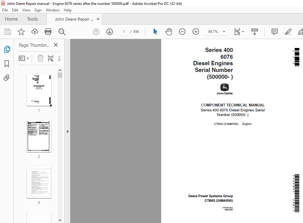
Serial Number (500000-)
FOREWORD :
This manual is written for an experienced technician. Essential tools required in performing certain service work are identified in this manual and are recommended for use. Live with safety: Read the safety messages in the introduction of this manual and the cautions presented throughout the text of the manual.
- This is the safety-alert symbol. When you see this symbol on the machine or in this manual, be alert to the potential for personal injury. Use this component technical manual in conjunction with the machine technical manual.
- An application listing in the introduction identifies product-model/component type-model relationship. See the machine technical manual for information on component removal and installation, and gaining access to the components.
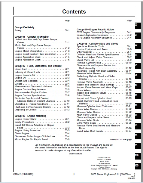
TABLE OF CONTENTS:
John Deere Series 400 6076 Diesel Engines Technical Manual – PDF DOWNLOAD
Group 00—Safety
Safety 00-1
Group 01—General Information
Unified Inch Bolt and Cap Screw Torque
Values 01-1
Metric Bolt and Cap Screw Torque
Values 01-2
Engine Model Designation01-3
Engine Serial Number Plate Information01-4
Engine Application Chart 01-5
Engine Application Chart 01-6
Group 02—Fuels, Lubricants, and Coolant
Diesel Fuel 02-1
Lubricity of Diesel Fuels 02-1
Engine Break-In Oil 02-2
Engine Oil 02-3
Oilscan and Coolscan02-4
Grease 02-4
Alternative and Synthetic Lubricants 02-5
Engine Coolant Requirements02-5
Recommended Engine Coolant02-7
Engine Coolant Specifications02-8
Replenish Supplemental Coolant
Additives Between Coolant Changes 02-10
Operating in Tropical Conditions 02-11
Flush and Service Cooling System 02-12
Disposing of Coolant 02-13
Group 03—Engine Mounting
Engine Repair Stand03-1
Safety Precautions 03-2
Install 400 Series Adapters on Repair
Stand03-2
Engine Lifting Procedure 03-3
Clean Engine 03-4
Disconnect Turbocharger Oil Inlet Line03-4
Mount Engine On Repair Stand 03-5
Page
Group 04—Engine Rebuild Guide
6076 Engine Disassembly Sequence 04-1
Sealant Application Guidelines04-2
6076 Engine Assembly Sequence 04-4
Group 05—Cylinder Head and Valves
Special or Essential Tools05-1
Service Equipment and Tools 05-3
Other Material 05-4
Cylinder Head and Valves Specifications 05-5
Check and Adjust Valve Clearance05-7
Check Valve Lift05-9
Remove Cylinder Head 05-10
Disassemble and Inspect Rocker Arm
Shaft Assembly 05-12
Assemble Rocker Arm Shaft Assembly 05-14
Measure Valve Recess 05-14
Preliminary Cylinder Head and Valve
Checks 05-15
Remove Valve Assembly05-16
Inspect and Measure Valve Springs 05-17
Inspect Valve Rotators and Wear Caps 05-17
Clean Valves 05-18
Inspect and Measure Valves05-18
Grind Valves 05-19
Inspect and Clean Cylinder Head05-19
Check Cylinder Head Combustion Face
Flatness05-20
Measure Cylinder Head Thickness 05-21
Clean Valve Guides05-22
Measure Valve Guides 05-22
Knurl Valve Guides05-23
Clean and Inspect Valve Seats 05-23
Measure Valve Seats 05-24
Grind Valve Seats 05-25
Remove Valve Seat Inserts and Measure
Bores 05-26
Install Valve Seat Inserts 05-27
Inspect and Clean Cylinder Head Nozzle
Bore05-27
Clean and Inspect Push Rods 05-28
Inspect and Clean Ventilator Outlet Hose 05-28
Clean and Inspect Top Deck of Cylinder
Block 05-29
Measure Cylinder Liner Standout (Height
above Block)05-30
Assemble Valve Assembly 05-31
Install Cylinder Head 05-32
Cylinder Head Cap Screw Types05-33
Clean, Inspect and Install Cylinder Head
Cap Screws 05-34
Torque-To-Yield Special Flanged-Head
Cap Screws 05-36
Install Rocker Arm Assembly05-37
Complete Final Assembly Of Injection
Pump Side 05-38
Complete Final Assembly On Exhaust
Manifold Side05-39
Perform Engine Break-In05-42
Group 10—Cylinder Block, Liners, Pistons and
Rods
Special or Essential Tools10-1
Service Equipment and Tools 10-3
Other Material 10-3
Cylinder Block, Liners, Pistons, and Rods
Specifications 10-4
Preliminary Liner, Piston, and Rod
Checks 10-8
Remove Pistons and Connecting Rods10-9
Measure Cylinder Liner Standout (Height
above Block)10-12
Remove Cylinder Liners10-13
Deglazing Cylinder Liners 10-14
Clean Cylinder Liners 10-15
Disassemble and Clean Piston 10-15
Visually Inspect Pistons 10-16
Check Piston Ring Groove Wear10-17
Measure Oil Control Ring Groove10-18
Install Piston Pin in Piston Pin Bore 10-18
Visually Inspect Cylinder Liners 10-19
Cylinder Liner Manufacturing Date Code
Explanation 10-20
Measure Piston Skirt OD10-21
Measure Cylinder Liner ID 10-22
Measure Liner Flange Thickness10-22
Inspect and Measure Connecting Rod
Bearings10-23
Inspect Rod and Cap 10-24
Page
Inspect Piston Pins and Bushings10-26
Remove Piston Pin Bushing 10-27
Clean and Inspect Piston Pin Bushing
Bore in Rod 10-27
Install Piston Pin Bushing in Connecting
Rod10-28
Complete Disassembly of Cylinder Block
(If Required) 10-29
Remove and Clean Piston Cooling
Orifices 10-29
Inspect and Clean Cylinder Block10-30
Clean O-Ring Bore 10-32
Measure Cylinder Block10-32
Install Piston Cooling Orifices and Gallery
Plugs 10-34
Recheck Cylinder Liner Standout (Height
above Block)10-35
Install Liner Shims—If Required 10-36
Install Cylinder Liner O-Rings and
Packings10-37
Install Cylinder Liners 10-38
Install Pistons and Connecting Rods 10-40
Torque-Turn Connecting Rod Cap Screws10-43
Check Engine Rotation for Excessive
Tightness10-43
Complete Final Assembly 10-44
Group 15—Crankshaft, Main Bearings and
Flywheel
Special or Essential Tools15-1
Service Equipment and Tools 15-4
Other Material 15-5
Crankshaft, Main Bearings, and Flywheel
Specifications 15-6
Failure Analysis 15-8
Remove Crankshaft Rear Oil Seal
Housing
(With Oil Seal Housing Installed)15-9
Install Crankshaft Rear Oil Seal and
Wear Sleeve
(Without Engine Disassembly) 15-11
Inspect Vibration Damper 15-12
Check Crankshaft End Play 15-13
Remove Damper Pulley15-14
Remove Front Oil Seal
(With Timing Gear Cover Installed on
Engine) 15-16
Remove Front Wear Sleeve
(With Timing Gear Cover Installed or
Removed) 15-17
Install Front Wear Sleeve
(With Timing Gear Cover Installed)15-17
Install Front Oil Seal
(With Timing Gear Cover Installed)15-18
Replace Timing Gear Cover
(6076HRW33, 34, and 35 Engines)
—Engine Installed in Vehicle 15-19
Remove Timing Gear Cover15-20
Inspect, Measure and Repair Flywheel 15-20
Check Flywheel Housing Face Run-Out 15-21
Check Flywheel Face Flatness 15-21
Check Pilot Bearing Bore Concentricity 15-22
Remove Flywheel 15-22
Remove SAE 1 and SAE 2 Flywheel
Housing 15-23
Remove SAE 3 Flywheel Housing15-23
Replace Flywheel Ring Gear15-24
Replace Rear Oil Seal Housing
(6076HRW33, 34, and 35 Engines)
—Engines Installed in Vehicle 15-25
Remove Rear Oil Seal Housing and
Wear Sleeve
(With Engine Disassembled) 15-26
Remove Crankshaft Main Bearings 15-27
Check Main Bearing Clearance 15-28
Remove Crankshaft15-29
Inspect Crankshaft 15-30
Measure Assembled ID of Bearings And
OD Of Crankshaft Journals15-32
Main Bearing Cap Line Bore
Specifications15-33
Crankshaft Grinding Guidelines 15-34
Thrust Bearing New Part Specifications 15-36
Crankshaft Grinding Specifications 15-37
Replace Crankshaft Oil Pump Drive Gear 15-38
Replace Crankshaft Gear 15-39
Inspect Thrust Bearings15-40
Remove and Clean Piston Cooling
Orifices 15-40
Install Main Bearings and Crankshaft 15-41
Install Crankshaft Rear Oil Seal Housing 15-43
Check Oil Seal Housing Runout 15-45
Crankshaft Rear Oil Seal And Wear
Sleeve Handling Precautions 15-46
Install Crankshaft Rear Oil Seal and
Wear Sleeve Assembly 15-47
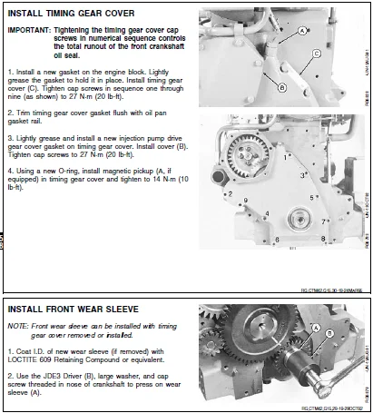
Install Timing Gear Cover 15-48
Page
Install Front Wear Sleeve 15-48
Install Front Oil Seal
(With Timing Gear Cover Installed)15-49
Install Damper Pulley Assembly 15-49
Install SAE 3 Flywheel Housing 15-50
Install Flywheel15-51
Install SAE 1 and SAE 2 Flywheel
Housing 15-51
Complete Final Assembly 15-52
Group 16—Camshaft and Timing Gear Train
Special or Essential Tools16-1
Service Equipment and Tools 16-3
Other Material 16-3
Camshaft and Timing Gear Train
Specifications 16-4
Check Valve Lift16-6
Check Camshaft End Play16-7
Remove Damper Pulley and Timing Gear
Cover16-7
Measure Camshaft Drive
Gear-to-Crankshaft Gear Backlash 16-8
Remove Camshaft 16-9
Remove Camshaft Gears 16-11
Measure Thrust Washer Thickness 16-11
Inspect and Measure Camshaft Followers 16-12
Visually Inspect Camshaft 16-12
Measure Camshaft Journal OD and
Bushing ID 16-13
Measure Camshaft Lobe Lift16-13
Install Camshaft Gears 16-14
Service Camshaft Bushings using
JDG602 Adapter Set 16-15
Service Camshaft Bushings using
JDG606 Adapter Set 16-17
Install Camshaft16-18
Install Thrust Washer and Timing Gear
Cover 16-20
Install Front Oil Seal
(With Timing Gear Cover Installed)16-21
Complete Final Assembly 16-22
Group 20—Lubrication System
Other Material 20-1
Lubrication System Specifications 20-1
Drain Engine Oil and Remove Oil Pan 20-2
Oil Filter and Oil Conditioning Housing
Assembly 20-3
Remove Oil Filter and Oil Conditioning
Housing 20-4
Inspect and Replace Oil Filter Adapter 20-4
Remove, Inspect, and Install Valves from
Oil Conditioning Housing 20-5
Install Oil Filter and Oil Conditioning
Housing 20-6
Remove Engine Oil Cooler 20-7
Clean, Inspect, and Install Engine Oil
Cooler20-8
Check Crankshaft Gear-To-Oil Pump
Drive Gear Backlash 20-9
Remove Engine Oil Pump20-9
Inspect and Clean Oil Pump20-10
Check Drive Shaft End Play20-11
Check Drive Shaft Side Movement 20-11
Check Pumping Gear Backlash 20-12
Inspect Oil Pump Drive Gear20-12
Install Engine Oil Pump 20-13
Install Oil Pan 20-14
Tighten cap screws on front frame/oil
sump 20-15
Group 25—Cooling System
Special or Essential Tools25-1
Other Material 25-2
Cooling System Specifications25-3
Service Equipment and Tools 25-5
Replace Bearings in Standard Duty,
Adjustable Fan Drive Assembly 25-6
Replace Bearings in Heavy Duty,
Adjustable Fan Drive Assembly 25-8
Water Manifold Mounted Fixed Fan Drive
Assembly25-10
Replace Bearing in Injection Pump Drive
Gear Mounted Fan Drive 25-12
Inspect and Check Belt Tensioner Spring
Tension 25-13
Replace Belt Tensioner Assembly25-14
Remove Water Pump 25-14
Disassemble Water Pump 25-15
Inspect Water Pump Parts 25-18
Assemble Water Pump 25-19
Install Water Pump 25-21
Remove and Test Thermostats 25-22
Install Thermostats 25-23
Remove Water Manifold25-23
Install Water Manifold 25-24
Remove Coolant Heater25-24
Install Coolant Heater 25-25
Complete Final Assembly 25-26
Page
Fan Belt Tension Specifications 25-26
Group 30—Air Intake And Exhaust System
Special or Essential Tools30-1
Other Material 30-2
Air Intake and Exhaust System
Specifications 30-2
Extending Turbocharger Life 30-4
Remove Turbocharger 30-6
Turbocharger Failure Analysis30-8
Turbocharger Seven-Step Inspection 30-10
Perform Radial Bearing Clearance Test 30-15
Perform Axial Bearing End Play Test 30-16
Repair Turbocharger30-16
Disassemble Turbocharger 30-17
Clean and Inspect Turbine and
Compressor Housings30-18
Replace Center Housing Assembly and
Assemble Turbocharger 30-19
Prelube Turbocharger 30-20
Install Turbocharger30-20
Remove, Inspect, and Install Intake
Manifold30-22
Remove Vertically-Mounted Aftercooler
and Intake Manifold 30-23
Remove and Disassemble
Horizontally-Mounted Aftercooler
Assembly30-25
Inspect and Repair Aftercooler 30-26
Inspect and Repair Intake Manifold and
Cover 30-26
Install Intake Manifold and
Vertically-Mounted Aftercooler 30-27
Assemble and Install
Horizontally-Mounted Aftercooler
Assembly30-29
Remove, Inspect, and Install Exhaust
Manifold30-31
Group 35—Fuel System
Special or Essential Tools35-1
Other Material 35-4
Diesel Fuel System Specifications 35-4
Relieve Fuel System Pressure35-6
Replace Rectangular Fuel Filter Element 35-6
Replace Fuel Check Valve 35-7
Remove Round Fuel Filter Element35-8
Identification of fuel supply and fuel
injection pumps 35-9
Remove Mechanical Fuel Supply Pump 35-10
Test Mechanical Fuel Supply Pump for
Leaks 35-11
Disassemble Mechanical Fuel Supply
Pump (Nippondenso) 35-12
Inspect and Repair Mechanical Fuel
Supply Pump (Nippondenso) 35-14
Assemble Mechanical Fuel Supply Pump
(Nippondenso) 35-15
Disassemble Mechanical Fuel Supply
Pump (Robert Bosch)35-16
Inspect and Repair Mechanical Fuel
Supply Pump (Robert Bosch) 35-17
Assemble Mechanical Fuel Supply Pump
(Robert Bosch) 35-18
Install Mechanical Fuel Supply Pump35-18
Remove and Install Electric Fuel Supply
Pump 35-19
Clean or Replace Electric Fuel Supply
Pump Filter Screen 35-20
Repair Aneroid35-21
Remove Hydraulic Aneroid Activator 35-21
Disassemble and Clean Hydraulic
Aneroid Activator Parts 35-22
Assemble and Install Hydraulic Aneroid
Activator35-22
Service Injection Pump Overflow Valve 35-22
Remove and Install Fuel Shutoff Solenoid 35-24
Identification of In-Line Injection Pumps 35-25
Remove In-Line Fuel Injection Pump 35-26
Install In-Line Fuel Injection Pump 35-29
Remove Rotary Fuel Injection
Pump—Stanadyne DB4 35-33
Install Rotary Fuel Injection
Pump—Stanadyne DB4 35-34
Remove Fuel Injection Nozzles 35-37
Diagnose Injection Nozzle Malfunction35-40
Test Fuel Injection Nozzles 35-42
Perform Opening Pressure Test 35-43
Injection Nozzle Specifications 35-44
Perform Nozzle Leakage Test 35-45
Perform Chatter and Spray Pattern Test 35-46
Disassemble Fuel Injection Nozzle 35-47
Clean and Inspect Fuel Injection Nozzle
Assembly35-49
Perform Nozzle Slide Test 35-50
Clean Spray Orifices35-50
Inspect Nozzle Holder 35-51
Inspect Gland Nut 35-53
Assemble Fuel Injection Nozzle 35-54
Adjust Injection Nozzles35-57
Page
Inspect and Clean Cylinder Head Nozzle
Bore35-58
Inspect and Clean Nozzle Seating
Surface 35-59
Install Fuel Injection Nozzles35-59
Group 100—Engine Tune-Up and Break-In
Effects of Altitude and Temperature on
Engine Performance 100-1
Preliminary Engine Testing 100-2
General Tune-Up Recommendations 100-3
Dynamometer Test 100-4
Engine Break-In Guidelines 100-5
Perform Engine Break-In100-6
Check Crankcase Ventilation System 100-7
Check Air Intake System100-7
Check Exhaust System 100-8
Check and Service Cooling System 100-8
Check Electrical System 100-10
Group 105—Engine System Operation and Test
Special or Essential Tools 105-1
Engine Test Specifications 105-3
Engine—Sectional View105-4
General Engine Description 105-5
How the Lubrication System Works 105-6
How the Cooling System Works105-10
Head Gasket Joint Construction and
Operation 105-12
Diagnosing Head Gasket Joint Failures 105-14
Head Gasket Inspection and Repair
Sequence **M:CTM42,G105,18 -19- 105-17
Diagnosing Engine Malfunctions105-18
Test Engine Compression Pressure 105-21
Check Engine Oil Pressure105-22
Inspect Thermostat and Test Opening
Temperature 105-24
Group 110—Air Intake System Operation and
Test
Special or Essential Tools 110-1
Air Intake and Exhaust System Test
Specifications110-2
Diagnosing Air Intake Malfunctions 110-3
How the Air Intake and Exhaust System
Works 110-4
Air Cleaner Operation 110-4
Diagnosing Turbocharger Malfunctions110-6
How The Turbocharger Works 110-7
How The Turbocharger is Lubricated 110-7
How The Aftercooler Works—6076A
Engines 110-8
Check Intake Manifold Pressure
(Turbocharger Boost) 110-9
Group 115—Fuel System Operation and Test
Special or Essential Tools 115-1
Fuel System Test Specifications 115-2
Check and Adjust Rotary fuel pump
Dynamic Timing 115-2
Fuel System Operation—In-Line Fuel
Injection Pump 115-10
Fuel System Operation—Rotary Fuel
Injection Pump 115-11
Diagnose Fuel System Malfunctions115-12
Mechanical Fuel Supply Pump Operation
Operation 115-16
Diagnosing Mechanical Fuel Supply
Pump Malfunctions 115-18
Test Mechanical Fuel Supply Pump for
Leaks 115-19
Check Mechanical Fuel Supply Pump
Operation 115-20
Service Mechanical Fuel Supply Pump 115-22
Electric Fuel Supply Pump Operation 115-23
Diagnose Electric Fuel Supply Pump
Malfunction115-24
Test Electric Fuel Supply Pump Output
Pressure and Flow 115-25
Fuel Shut-Off Solenoid Resistance Test 115-27
Rectangular Fuel Filter Operation 115-28
Round (Final) Fuel Filter Operation 115-28
Bleed the Fuel System115-29
Diagnose In-Line Fuel Injection Pump
Malfunctions115-32
In-Line Fuel Injection Pump Operation 115-33
Check Fast Idle Speed—In-Line Fuel
Injection Pump 115-34
Check and Adjust Engine Slow Idle
Speed—In-Line Fuel Injection Pump 115-35
Rotary Fuel Injection Pump
Operation—Stanadyne DB4 115-38
Diagnose Rotary Fuel Injection Pump
Malfunctions115-40
Check and Adjust Engine Speeds on
Rotary Pump 115-41
How the Aneroid Works—In-Line Injection
Pumps115-42
Diagnose Aneroid Malfunctions 115-43
Page
How the Hydraulic Aneroid Activator
Works 115-44
Diagnose Malfunctions—Hydraulic
Aneroid Activator 115-45
Fuel Injection Nozzles—General
Information 115-46
Fuel Injection Nozzle Operation115-47
Diagnose Malfunctions—Fuel Injection
Nozzle115-48
Test Fuel Injection Nozzles (Engine
Running) 115-49
Fuel Drain Back Test Procedure115-49
Group 199—Dealer Fabricated Tools
How to Make Tools199-1
Cylinder Liner Holding Fixture 199-1
Index
IMAGES PREVIEW OF THE MANUAL:
JOHN DEERE SERIES 400 6076 DIESEL ENGINES TECHNICAL MANUAL – PDF DOWNLOAD:
PLEASE NOTE:
- This is the SAME manual used by the dealers to troubleshoot any faults in your vehicle. This can be yours in 2 minutes after the payment is made.
- Contact us at [email protected] should you have any queries before your purchase or that you need any other service / repair / parts operators manual.
S.V