John Deere Tractors 7600 7700 7800 Diagnostic &Test Manual – PDF DOWNLOAD
Original price was: $75.95.$29.95Current price is: $29.95.
John Deere Tractors 7600 7700 7800 Diagnostic &Test Manual – PDF DOWNLOAD
Description
John Deere Tractors 7600 7700 7800 Diagnostic &Test Manual – PDF DOWNLOAD
DESCRIPTION:
John Deere Tractors 7600 7700 7800 Diagnostic &Test Manual – PDF DOWNLOAD
For complete service information also see:
Repair manual 7600, 7700, 7800
tractors
TM1500
Series 400, 6076 diesel engine. Repair
manual
CTM42
Series 3029, 4039, 4045, 6059, 6068
diesel engine. Repair manual
CTM3274
Operation manual 7600, 7700, 7800
tractors
OMAR112756
Foreword:
This manual is written for an experienced technician. Essential tools required in performing certain service work are identified in this manual and are recommended for use. Live with safety: Read the safety messages in the introduction of this manual and the cautions presented throughout the text of the manual.
- This is the safety-alert symbol. When you see this symbol on the machine or in this manual, be alert to the potential for personal injury. Technical manuals are divided in two parts: repair and operation and tests. Repair sections tell how to repair the components. Operation and tests sections help you identify the majority of routine failures quickly.
- Information is organized in groups for the various components requiring service instruction. At the beginning of each group are summary listings of all applicable essential tools, service equipment and tools, other materials needed to do the job, service parts kits, specifications, wear tolerances, and torque values.
- Technical Manuals are concise guides for specific machines. They are on-the-job guides containing only the vital information needed for diagnosis, analysis, testing, and repair. Fundamental service information is available from other sources covering basic theory of operation, fundamentals of troubleshooting, general maintenance, and basic type of failures and their causes.
TABLE OF CONTENTS:
John Deere Tractors 7600 7700 7800 Diagnostic &Test Manual – PDF DOWNLOAD
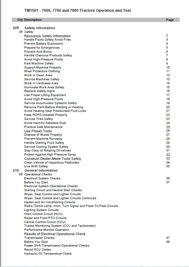
205 Safety Information
05 Safety
Recognize Safety Information 2
Handle Fluids Safely Avoid Fires 3
Prevent Battery Explosions 4
Prepare for Emergencies 5
Prevent Acid Burns 6
Handle Chemical Products Safely 7
Avoid High-Pressure Fluids 8
Park Machine Safely 9
Support Machine Properly 10
Wear Protective Clothing 11
Work in Clean Area 12
Service Machines Safely 13
Work In Ventilated Area 14
Illuminate Work Area Safely 15
Replace Safety Signs 16
Use Proper Lifting Equipment 17
Avoid High-Pressure Fluids 18
Service Accumulator Systems Safely 19
Remove Paint Before Welding or Heating 20
Avoid Heating Near Pressurized Fluid Lines 21
Keep ROPS Installed Properly 22
Service Tires Safely 23
Avoid Harmful Asbestos Dust 24
Practice Safe Maintenance 25
Use Proper Tools 26
Dispose of Waste Properly 27
Prevent Machine Runaway 28
Handle Starting Fluid Safely 29
Service Cooling System Safely 30
Stay Clear of Rotating Drivelines 31
Protect Against High Pressure Spray 32
Construct Dealer-Made Tools Safely 33
Clean Vehicle of Hazardous Pesticides 34
Live With Safety 35
210 General Information
05 Operational Checks
Electrical System Checks 36
Before You Start 37
Electrical System Operational Checks
Starting Circuit and Neutral Start Checks
Wiper, Seat Control and Lighter Circuits
Wiper, Seat Control and Lighter Circuits Continued
Heater and Air Conditioning Circuits
Radio, Dome Lamp, Horn, Turn Signal and Flash-To-Pass Circuits
Lighting System Circuits
Hitch Control Circuit (HCU)
Radar and Front PTO Circuits
Central Control Circuit (CCU)
Tractor Monitoring System (CCU and Tachometer)
Performance Monitor Operation
Results of Electrical Operational Check
Transmission Checks 47
Before You Start 48
Power Shift Transmission Operational Checks
Recall PCU Codes
Hydraulic Oil Temperature Check
Exit Diagnostic Mode
Neutral to Gear Engagement and Modulation Check
Forward to Reverse (Shuttle Shift) Modulation Check
Gear to Gear Modulation Check
Clutch Modulation With Pedal
C1-C2 Traction Clutch Check
Clutch Engagement Check
Differential Lock Operational Check
MFWD Operational Check
PTO Operational Check
Recall Codes
Neutral to Gear Modulation Check
Forward to Reverse Modulation Check
Gear to Gear Modulation Check
Range Box Check
Clutch Modulation With Clutch Pedal
Transmission Creep Check
Clutch Engagement Check
Differential Lock Operational Check
MFWD Operational Check
PTO Operational Check (Front or Rear)
Hydraulic System Checks 56
Hydraulic System Operational Checks
Hydraulic System Load Check
Hydraulic Operational Check
Driving Checks
Hitch Operational Checks
Hitch Setup
Operate Hitch Controls
Hitch Operational Checkout Results
Air Conditioning System Checks 60
A/C System Operational Checks
Engine Off Checks
Blower Motor Check
Air Distribution Check
Engine Running Checks
Temperature Drop Check
Check Heater Valve Operation
Results of Operational Check
10 General Reference Information
JT03412 Supplemental Pressure Test Kit 63
JT03413 Supplemental Flow Test Kit 64
JT03419 ORFS Fitting Kit 65
JT05406 Master Hydraulic Flow Test Fitting Kit 66
JT05416 Consumer Products Hydraulic Flow Test Kit 69
JT05452 Power Shift Transmission Test Kit 70
JT03134 Power Shift Transmission Optional Accessories 71
JT05469 Flowmeter Kit 72
JT05470 Agricultural Universal Pressure Test Kit 73
Required Test Fittings 74
List of Diagnostic Adapters ORFS 75
Unified Inch Bolt and Screw Torque Values 76
Metric Bolt and Screw Torque Values 78
JIC Hydraulic Symbols 79
Glossary of Terms 80
15 Test Equipment Calibration
JDG282 Temperature Gauge Check 82
Calibration Check of OTC Flow Meters 83
Method No. 1: Flow Meter (Main Pump Quick Check From SCV) 84
Method No. 2: Volume Check From Flow Meter 85
Pressure Gauge Calibration Checker 87
211 Diagnostic Service Codes
05 CCU
CCU 001 – Fuel Level Sensor Circuit, Repair 93
CCU 003 – Fuel Level Low 94
Preliminary Check
Fuel Level Sensor Circuit Check
CCU 010 – Engine Coolant Temperature High, Repair 95
CCU 011 – Engine Coolant Temperature Very High, Repair 96
CCU 012 – Coolant Temperature Sensor \ Circuit Open, Repair 97
CCU 013 – Coolant Temperature Sensor \ Circuit Shorted, Repair 98
CCU 015 – Hydraulic Oil Temperature High, Repair 99
CCU 016 – Hydraulic Oil Temperature Very High, Repair 100
CCU 017 – Hydraulic Oil Temperature Sensor Circuit Open, Repair 101
CCU 018 – Hydraulic Oil Temperature Sensor Circuit Shorted, Repair 102
CCU 021 – Engine Oil Pressure Low (Pressure Switch), Repair 103
CCU 026 – Transmission Oil Pressure Low, Repair 104
CCU 030 – Engine Air Filter Restricted, Repair 105
CCU 035 – Transmission Oil Filter Restricted, Repair 106
CCU 045 – System Voltage Too Low (Idle-to-1500 rpm), Repair 107
CCU 046 – System Voltage Too Low (Above 1500 rpm), Repair 108
CCU 047 – System Voltage Too High (Engine running), Repair 109
CCU 048 – CCU Supply Voltage Low w/Engine OFF 110
Preliminary Check
Battery Inspection
Circuit Check
ELX Relay Check
CCU 050 – Hydraulic Oil Filter Restricted, Repair 112
CCU 055 – Secondary Hand Brake ON when Moving 113
Preliminary Check
Brake Switch Test
CCU 060 – High Pressure In Steering Hydraulic System, Repair 114
CCU 067 – Sensor Power Source (12V) Missing Fuse F1, Repair 115
CCU 070 – Operator Not Seated w/Rear PTO ON 116
Preliminary Check
Rear PTO Switch Circuit Test
Operator Presence Switch Test
CCU 071 – PTO Switch ON at Power Up 118
Preliminary Check
Rear PTO Switch Circuit Test
CCU 072 – Rear PTO Control Switch/Circuit Failed, Repair 119
CCU 073 – Rear PTO Solenoid/Circuit Failed, Repair 120
CCU 075 – Rear PTO Speed Too Low with PTO ON, Repair 121
CCU 077 – Operator Not Seated w/Front PTO ON 122
Preliminary Check
Operator Presence Switch Test
Front PTO Sense Lines Test
CCU 078 – Front PTO-Switch OFF But Solenoid ON, Repair 124
CCU 080 – Differential Lock Switch Stuck ON, Repair 125
CCU 081 – Differential Lock Circuit Fault With Switch ON, Repair 126
CCU 085 – MFWD Control Switch Error, Repair 127
CCU 086 – MFWD Circuit Fault With Switch OFF, Repair 128
CCU 093 – Clutch Cooling Solenoid Circuit Failure 129
CCU 094 – Fuel Advance Solenoid Circuit Failure 130
CCU 101 – Clutch Cooling Not Allowed 131
CCU 102 – HMS Not Allowed 132
CCU 103 – HMS Disabled w/Towed Implement Mode Active 133
CCU 104 – Remote PTO Operation Not Allowed 134
CCU 105 – Self-Canceling Turn Signals Not Allowed 135
CCU 255 – Phantom Code 136
10 HCU
HCU 022 – Battery Voltage Out of Range, Repair 137
HCU 027 – Calibration Not Successful, Repair 138
HCU 028 – Calibration Memory Failure, Repair 139
HCU 029 – Calibration Selected For Less Than 30 Seconds, Repair 140
HCU 041 – Pressure Valve Solenoid Circuit, Repair 141
HCU 042 – Return Valve Solenoid Circuit, Repair 142
HCU 043 – Pressure Valve Solenoid Circuit, Repair 143
HCU 044 – Return Valve Solenoid Circuit, Repair 144
HCU 045 – Sensor Supply Voltage Out of Range, Repair 145
HCU 049 – Raise/Lower Rocker Switch Circuit, Repair 146
HCU 050 – HCU Failure, Repair 147
HCU 052 – Draft Sensor Circuit, Repair 148
HCU 053 – Load/Depth Control Potentiometer Circuit, Repair 149
HCU 054 – Hitch Control Lever Potentiometer Circuit, Repair 150
HCU 055 – Hitch Position Feedback Sensor Circuit, Repair 151
HCU 056 – Raise Limit Control Potentiometer Circuit, Repair 152
HCU 057 – Rate-of-Drop Control Potentiometer Circuit, Repair 153
HCU 058 – External Raise/Lower Switch Circuit, Repair 154
15 LHP
LHP 022 – Battery Voltage Out of Range, Repair 155
LHP 027 – Calibration Not Successful, Repair 156
LHP 028 – Calibration Memory Failure or Never Calibrated, Repair 157
LHP 029 – Calibration Selected For Less Than 30 Seconds, Repair 158
LHP 045 – Sensor Supply Voltage Out of Range, Repair 159
LHP 050 – Row-Trak Control Unit Failure, Repair 160
LHP 054 – Position Control Circuit, Repair 161
LHP 055 – Pivot Angle Circuit, Repair 162
LHP 056 – Response Rate Control Circuit, Repair 163
LHP 057 – Row Sensor Circuit, Repair 164
LHP 058 – Row Sensor Raise Circuit, Repair 165
LHP 059 – Row Sensor Lower Circuit, Repair 166
LHP 060 – CCD Communication Line Failure, Repair 167
LHP 141 – Extend Valve Solenoid Circuit, Repair 168
LHP 142 – Retract Valve Solenoid Circuit, Repair 169
LHP 143 – Extend Valve Solenoid Circuit, Repair 170
LHP 144 – Retract Valve Solenoid Circuit, Repair 171
20 PCU
PCU 008 – Manifold Absolute Pressure Sensor Out of Range, Repair 172
PCU 011 – Oil Temperature Is Cold For Proper Input Planetary Operation, Repair 173
PCU 012 – Oil Pressure Is Low For Proper Input Planetary Operation, Repair 174
PCU 016 – Excessive Engine Oscillation During Calibration, Repair 175
PCU 018 – Fault Detected In Diagnostic Mode, Repair 176
PCU 019 – PCU Not Calibrated For 30 km/h-40 km/h Speed, Repair 177
PCU 027 – Transmission Not Calibrated, Repair 178
PCU 028 – B4 Element Not Calibrated, Repair 179
PCU 030 – Clutch Engaged and Disengaged Switch Conflict (Both Closed), Repair 180
PCU 031 – Both Clutch Engaged and Disengaged Switches Open For Too Long (“Riding the 181
PCU 038 – EOL Data Error, Repair 182
PCU 039 – Reverse Enable Circuit Fault, Repair 183
PCU 040 – Forward Enable Circuit Fault, Repair 184
PCU 041 – Forward and Reverse Enable Circuit Conflict (Both Enabled), Repair 185
PCU 042 – Command Conflicts With Enable Circuit (Reverse Commanded/Forward Enabled), 186
PCU 043 – Command Conflicts With Enable Circuit (Forward Commanded/Reverse Enabled), 187
PCU 044 – Command Conflicts With Enabled Circuit (Forward or Reverse 188
PCU 045 – Command Conflicts With Enabled Circuit (Neutral or Park Commanded/Transmission IS 189
PCU 047 – Shift Lever Between “N’ and “1F” or “1R” Too Long, Repair 190
PCU 050 – No Tractor Motion-Engine OFF, Repair 191
PCU 051 – No Tractor Motion-Engine Running, Repair 192
PCU 058 – Tractor Moved During Calibration, Repair 193
PCU 065 – PCU Fault (Checksum Error), Repair 194
PCU 066 – Key Switch ON with Transmission in Gear, Repair 195
PCU 067 – Transmission Enable Circuit Fault, Repair 196
PCU 068 – Gear Command Fault 197
PCU 069 – Calibration Failure, Repair 198
212 Observable Symptoms
10 Brakes
Brakes Function Erratically 199
Observable Symptoms
Brake Operational Check
20 Hitch
Hitch only moves with External Switch 200
Observable Symptom Diagnosis
Preliminary Checks
30 Operators Station
Digital Tachometer Display Not Functioning 201
Observable Symptom Diagnosis
Preliminary Check
Circuit Check
Fuse F7 Check
ELX Supplied Component Check
Fuse F4 Check
Controller Check
Controller Power Check
Controller Ground Check
CCD Check
Poor AM & FM Radio Reception or Electrical Noise 205
Observable Symptom Diagnosis
Preliminary Checks
Antenna Ground Cable
Antenna Lead to Radio
Remove Capacitor
Air Compressor Blower Induced Interference
Alternator Induced Interference
Tachometer Induced Interference
Key Switch Won’t Return to Run Position 208
Key Switch
Key Switch Check
70 Hydraulics
Grapple Valve Holds System Pressure Above Standby for Several Seconds 209
Observable Diagnostics
Grapple Valve
220 Engine Operation and Tests
05 General Information
Engine Operation and Tests 210
230 Fuel, Air Intake and Engine Cooling Systems
20 Fuel/Air/Cooling System Theory of Operation
Fuel System 211
Air Intake System 212
Engine Cooling System 213
240 Electrical Operation and Tests
04 Diagnostic Codes and Addresses
Diagnostic Codes and Addresses 215
Enter/Exit Diagnostic Mode
Enter “dIA” Mode
Access Control Unit
Exit “dIA” Mode
Clear Diagnostic Codes
Enter “dIA” Mode
Clear Codes
Exit “dIA” Mode
Diagnostic Codes 219
CCU Diagnostic Code Numbers 220
HCU Diagnostic Code Numbers 222
LHP Diagnostic Code Numbers 223
PCU Diagnostic Code Numbers 224
CCU Addresses 225
HCU Addresses 227
LHP Addresses 228
PCU Addresses 229
PRF Addresses 230
05 Electrical System Information
Service Equipment and Tools 231
Other Material 232
Specifications 233
Using Electrical Section 235
Wiring Diagram and Schematic Information 236
Electrical Schematic Symbols 238
Reading a System Functional Schematic 239
Reading a Wiring Diagram 240
Reading a Diagnostic Schematic 242
Visually Inspect Electrical System 243
Seven Step Electrical Test Procedure 244
Electrical Circuit Malfunctions 245
High Resistance or Open Circuit 246
Grounded Circuit 247
Shorted Circuit 248
Understanding Electrical vs. Electronic Circuit Voltage Test Readings 249
Intermittent Electronic Problems 252
10 System Diagrams
Component Identification Legend 254
Component Identification Table 261
Legend for System Functional Schematic (Cab) 262
Legend for System Functional Schematic (Open Station) 263
Ground Locations 264
System Functional Schematic Cab SE1 (Power Supply, Starting and Charging Circuits), SE2
(Wiper, Seat Control and Lighter Circuits), and SE3 (Air Q
265
System Functional Schematic Cab SE4 (Radio, Dome Lamp and Multi-Function Switch) and SE5A
(Lighting System – Region I)
266
System Functional Schematic Cab SE4 (Radio, Dome Lamp and Multi-Function Switch) and SE5B
(Lighting System – Region II)
267
System Functional Schematic Cab SE6 (Hitch Control Unit – HCU), SE7 (PST Control Unit – PCU)
and SE8 (Radar and Front PTO Circuits)
268
System Functional Schematic Cab SE9 (Central Control Unit – CCU) and SE10 (Display Modules) 269
System Functional Schematic Open Station SE1 (Power Supply, Starting System), SE2 (Seat
Control System), SE3 (Convenience Outlet), SE4 (Radio, Lig
270
System Functional Schematic Open Station SE5 (Domestic Lighting) and SE6 (Hitch Control Unit –
HCU)
271
System Functional Schematic Open Station SE7 (PST Control Unit – PCU), SE8 (Radar and Front
PTO Circuits) and SE9 (Central Control Unit – CCU)
272
System Functional Schematic Open Station SE10 (Display Modules) 273
Fuse Panel (W2, W3, W4, W5, W28) (F1 F12) 274
Fuse Panel (W2, W3, W4, W5, W28) (F13 F20) 275
Fuse Panel (W2, W3, W4, W5, W28) (F21 F33) 276
Fuse Panel (W2, W3, W4, W5, W28) (F34 F36) 277
Load Center Relays (W2, W3, W4, W5, W28) (K1 K5) 278
Load Center Relays (W2, W3, W4, W5, W28) (K6 K9) 279
Load Center Relays (W2, W3, W4, W5, W28) (K10 K18) 280
Diode Blocks (W2, W3, W4, W5, W28) (V2 V3) 281
Cab/Open Operator Station Harness (W2, W3, W4, W5, W28) (A1 A2) 282
Cab/Open Operator Station Harness (W2, W3, W4, W5, W28) (A3) 283
Cab/Open Operator Station Harness (W2, W3, W4, W5, W28) (A4) 284
Cab/Open Operator Station Harness (W2, W3, W4, W5, W28) (A5 E3) 285
Cab/Open Operator Station Harness (W2, W3, W4, W5, W28) (E4 E9) 286
Cab/Open Operator Station Harness (W2, W3, W4, W5, W28) (E10 H5) 287
Cab/Open Operator Station Harness (W2, W3, W4, W5, W28) (J1 K18) 288
Cab/Open Operator Station Harness (W2, W3, W4, W5, W28) (K24 K31) 289
Cab/Open Operator Station Harness (W2, W3, W4, W5, W28) (K32 R3) 290
Cab/Open Operator Station Harness (W2, W3, W4, W5, W28) (R7 S5) 291
Cab/Open Operator Station Harness (W2, W3, W4, W5, W28) (S7 S18) 292
Cab/Open Operator Station Harness (W2, W3, W4, W5, W28) (S19 S33) 293
Cab/Open Operator Station Harness (W2, W3, W4, W5, W28) (S34 X1) 294
Cab/Open Operator Station Harness (W2, W3, W4, W5, W28) (X2 X10) 295
Cab/Open Operator Station Harness (W2, W3, W4, W5, W28) (X11 X21) 296
Cab/Open Operator Station Harness (W2, W3, W4, W5, W28) (X22 X30) 297
Cab/Open Operator Station Harness (W2, W3, W4, W5, W28) (X31 Y9) 298
PST and Cab Harness Routing/Component Location (North American) 299
PST and Cab Harness Routing/Component Location (European) 301
Open Operator Station Harness Routing/Component Location 303
Engine Harness (W6, W7) (B2 K21) 304
Engine Harness (W6, W7) (K22 X3) 305
Engine Harness (W6, W7) (X27 Y7) 306
Engine Harness Routing/Component Location (7600) 307
Engine Harness Routing/Component Location (7700) 308
Engine Harness Routing/Component Location (7800) 309
Transmission Sensor Harness (W8 and W9) (B5 S37) 310
Transmission Sensor Harness (W8 and W9) (W31 Y24) 311
PST Transmission Solenoid Harness (W10) (S27 Y19) 312
Transmission Harnesses Routing/Component Location (PST) 313
Transmission Harnesses Routing/Component Location (PQT) 314
Turn Signal Switch Harness (W15) 315
Wiper Switch Harness (W16) 316
Roof Lights Harness (W11 and W12) and Front Floods Harness (W13) 317
Hitch Controls Harness (W14) and Convenience Outlet Harness (W17) 318
Seat Harnesses (Air Suspension W25 and Mechanical Suspension W26) 319
Front PTO Harness (W29 and W34) 320
15 Sub-System Diagnostics
Starting Circuit 321
Starting Circuit Operational Information 323
Starting Circuit Theory of Operation 324
Voltage Checks 325
Starting Circuit (SE1)
Starter Operational Check
Isolating Cause for Starting In Gear
Starter Operational Check Continued
Isolating Cause for Slow Cranking Speed
Starter Solenoid Check
Causes for Improper Starter Operation
Causes for Improper Starter Operation
Causes for No Start or Hard Starting Engine
Starting Fluid Solenoid Operational Check
Cold Ambient Temperature and/or Start Aid Solenoid Related Starting Problems
Component Test Specifications
Key Switch (S1)
Neutral Start Switch (PST) (S4)
Test “ELX” Relay (K13) and “ACC” Relay (K14)
Start Aid Switch (S2)
Start Aid Solenoid (Y1)
Fuel Shut Off Solenoid (7600 and 7700) (Y3)
Fuel Shut Off Solenoid (7800) (Y4)
Manifold Heater Coil (7600) (R1)
Electric Fuel Pump (7700) (Y2)
Starting Motor (Including Solenoid) (M1)
Starting Circuit Relay (K21)
Power Supply Circuit 333
Power Circuit Operational Information 335
Power Circuit Theory of Operation 336
Batteries (G1)
Battery Inspection
Check Electrolyte Level of All Cells
Check Specific Gravity of Each Cell
Check Individual Battery Voltage
Charge Batteries
Select Charging Rate
Charge Batteries Continued
Check Battery Condition
Temperature Correction Chart 341
Transient Voltage Protector
Check Transient Voltage Protector
Charging Circuit 342
Charging System Operational Information 343
Charging Circuit Theory of Operation 344
Voltage Checks 345
Charging Circuit (SE1)
Check Stored Codes
Check Alternator Output Voltage
Alternator Overcharging
Alternator High Voltage and Warning Check
Battery-Alternator Circuit Check
Alternator “IG” Circuit Check
Alternator Output Voltage Check (Regulated)
Alternator Output Voltage Check (Non-Regulated)
Causes for Low Alternator Output
Alternator Output Capacity Check
Electrical System Leakage Check
System Leak Check (Continued)
Alternator Check
Field Circuit Current Draw Check
Rectifier Diode Checks
Stator Assembly Continuity Check
Wiper Circuit 354
Wiper Circuit Operational Information 356
Wiper Circuit Theory of Operation 357
Voltage Checks 358
Circuit Diagnosis
Wiper Circuit Relays (K15, K24 and K25)
Front Wiper Motor Switch (S8)
Rear Wiper Motor Switch (S5)
Front Wiper Motor (M3)
Rear Wiper Motor (M4)
Washer Pump Motors (M5 and M6)
Wiper Circuit Input/Output Signals at CCU (Intermittent Cycle)
Using CCU Diagnostic Mode
Access On-Board CCU Diagnostic Mode
Address 15 Wiper Time Delay Switch
Ground Fault Circuit Interrupter/Heaters 362
Ground Fault Circuit Operational Information 363
G.F.C.I. Circuit Theory of Operation 364
Voltage Checks 365
Component Tests
G.F.C.I.
Engine Heater
Transmission Heater
Charge Pump Heater
Seat Circuit 367
Seat Circuit Operational Information 369
Seat Circuit Theory of Operation 370
Voltage Checks 372
Component Tests
Seat Raise/Lower Switch (S6)
Compressor (M2)
Bleed Valve Solenoid (Y5)
Seat Switch (S7)
Raise/Lower Limit Switches
Up-stop Solenoid Circuit
RZP Bar Diodes
Seat Harness Diode
Using CCU Diagnostic Mode
Access On-Board CCU Diagnostic Mode
Address 11 Seat Switch
Cigarette Lighter Circuit 376
Lighter Circuit Operational Information 377
Lighter Circuit Theory of Operation 378
Voltage Checks 379
Component Tests
Cigarette Lighter (E1)
AQS and Convenience Outlet Circuits Schematic 380
AQS and Convenience Outlet Circuits Diagnostic Schematic 381
Air Quality System Diagnosis 382
Voltage Checks 383
Air Quality System Diagnosis
Test Relays K16, K26, K27 and K28
Blower Motor Switch (S9)
Blower Motor Resistor (R3)
Blower Motors (M7 and M8)
Pressurizer Blower Motor (M9)
A/C Deicing Switch (B1)
High and Low Refrigerant Pressure Switches (B2 and B3)
Compressor Clutch (Y7)
Radio, Dome Lamp and Multi-Function Control Circuits Schematic 386
Radio, Dome Lamp and Multi-Function Control Circuits Diagnostic Schematic 387
Horn Circuit Operational Information 388
Horn Circuit Theory of Operation 389
Voltage Checks 390
Circuit Diagnosis
Horn Switch
Horn
Dome Lamp Circuit Operational Information 391
Dome Lamp Circuit Theory of Operation 392
Voltage Checks 393
Circuit Diagnosis
Dome Lamp Switch
Check Door Switch
Check Dome Lamp
Radio and Clock Circuit Operational Information 394
Radio and Clock Circuit Theory of Operation 395
Voltage Checks 396
Circuit Diagnosis
Radio Service
Check Radio Antenna
Lighting System Schematic (North American) 397
Lighting System Diagnostic Schematic (North American) 398
Lighting Circuit Operational Information (North American) 400
Lighting Circuit Operation (North American) 401
Lighting Circuit Theory of Operation (North American) 402
Turn Signal and Warning Lights Circuit Theory of Operation 403
Voltage Checks 404
Circuit Diagnosis
Test Relay (N A)
Test Light Switch (N A) (S17)
Test Warning Light Switch (N A) (S18)
Warning/Hazard Flasher Circuit (N A)
Test Turn Signal Switch (N A) (S15)
Turn Signal Flasher Circuit (CCU) (N.A.)
Remove CCU Connector
Enter Diagnostic Mode
Right Turn Signal Check
Test HI/LO Beam Switch (N A) (S16)
Test Flash-To-Pass Switch (N A) (S38)
Using CCU Diagnostic Mode
Access On-Board CCU Diagnostic Mode
Address 19 Warning Lights Switch
Lighting System Schematic (European) 409
Lighting System Diagnostic Schematic (European) 410
Lighting Circuit Operational Information (European Version) 412
Lighting Circuit Operation (European) 413
Lighting Circuit Theory of Operation (European) 414
Turn Signal and Warning Lights Circuit Theory of Operation 415
Voltage Checks 416
Component Tests
Test Relay (European)
Test Road Light (S17) and Field Light (S20) Switches (European)
Test Turn Signal Switch (S15) (European)
Turn Signal Flasher Circuit (European)
Remove CCU Connector
Enter Diagnostic Mode
Right Turn Signal Check
Replace Flasher Unit
Battery Voltage Check
Test Warning Light Switch (S18) (European)
Warning Light Flasher Circuit (European)
Test Hi/Lo Beam Switch (S16) (European)
Hitch Control Circuit Schematic 420
Hitch Control Circuit Diagnostic Schematic 421
Hitch System Diagnosis 422
PST Control Circuit Schematic 423
PST Control Circuit Diagnostic Schematic 424
Power Shift Transmission Control Circuit Diagnosis 425
Radar Sensor Circuit 426
Front PTO Circuit (North American) 427
Front PTO Circuit Theory of Operation 429
Using CCU Diagnostic Mode
Access On-Board CCU Diagnostic Mode
Address 10 Front PTO Sense Lines
Front PTO Circuit (EUR) 431
CCU Fault Code Numbers 432
CCU Input Output Signals 434
Check CCU Circuit
CCU and CCU Circuit Check
Differential Lock Circuit 437
Differential Lock Circuit Theory of Operation 438
Voltage Checks 439
Component Tests
Differential Lock Switch (S34)
Differential Lock Solenoid (Y21), MFWD Solenoid (Y22), Rear PTO Solenoid (Y24)
Brake Switches (S30 and S31)
Using CCU Diagnostic Mode
Access On-Board CCU Diagnostic Mode
Address 6 Brake Switches
Address 7 Clutch, Neutral and Differential Lock Switches
MFWD Circuit 442
MFWD Circuit Theory of Operation 444
Voltage Checks 446
Component Tests
Brake Switches (S30 and S31)
MFWD Switch (S33)
Differential Lock Solenoid (Y21), MFWD Solenoid (Y22), Rear PTO Solenoid (Y24)
Rear PTO Speed Sensor (B16), Engine Speed Sensor (B17)
Wheel Speed Sensor With Creeper (B19)
Using CCU Diagnostic Mode
Access On-Board CCU Diagnostic Mode
Address 5 Wheel Speed and True Ground Speed
Address 6 Brake Switches
Address 8 MFWD Switch
Rear PTO Circuit 451
Rear PTO Circuit Theory of Operation 452
Voltage Checks 454
Component Tests
Rear PTO Switch (S32)
Differential Lock Solenoid (Y21), MFWD Solenoid (Y22), Rear PTO Solenoid (Y24)
Seat Switch (S7)
Rear PTO Speed Sensor (B16), Engine Speed Sensor (B17)
Using CCU Diagnostic Mode
Access On-Board CCU Diagnostic Mode
Address 4 Engine Speed and PTO Speed
Address 9 Rear PTO Switch
Address 11 Seat Switch
Clutch Cooling Circuit (Early Transmissions) 458
Clutch Cooling Circuit Theory of Operation (Early Transmissions) 459
Using CCU Diagnostic Mode
Access On-Board CCU Diagnostic Mode
Address 7 Clutch, Neutral and Differential Lock Switches
Wheel Speed Sensor Circuit 462
Wheel Speed and True Ground Speed 463
Voltage Checks 464
Component Tests
Differential Lock Solenoid (Y21), MFWD Solenoid (Y22), Rear PTO Solenoid (Y24)
Rear PTO Speed Sensor (B16), Engine Speed Sensor (B17)
Using CCU Diagnostic Mode
Access On-Board CCU Diagnostic Mode
Address 5 Wheel Speed and True Ground Speed
Engine Speed Sensor Circuit 466
Voltage Checks 468
Component Tests
Rear PTO Speed Sensor (B16), Engine Speed Sensor (B17)
Using CCU Diagnostic Mode
Access On-Board CCU Diagnostic Mode
Address 4 Engine Speed and PTO Speed
Fuel Level Sender Circuit 470
Voltage Checks 472
Component Tests
Fuel Level Sensor (B13)
Using CCU Diagnostic Mode
Access On-Board CCU Diagnostic Mode
Address 16 Fuel Level Sender
System Voltage Monitoring Circuit 474
Using CCU Diagnostic Mode
Access On-Board CCU Diagnostic Mode
Address 4 Engine Speed and PTO Speed
Address 32 System Voltage
Engine Coolant Temperature Sensor Circuit 477
Voltage Checks 479
Component Tests
Engine Coolant Temperature Sensor (B14) and Hydraulic Oil Temperature Sensor (B15)
Using CCU Diagnostic Mode
Access On-Board CCU Diagnostic Mode
Address 4 Engine Speed and PTO Speed
Address 18 Engine Coolant Temperature Sender
Hydraulic Oil Temperature Circuit 482
Voltage Checks 484
Component Tests
Engine Coolant Temperature Sensor (B14) and Hydraulic Oil Temperature Sensor (B15)
Using CCU Diagnostic Mode
Access On-Board CCU Diagnostic Mode
Address 4 Engine Speed and PTO Speed
Address 17 Hydraulic Oil Temperature Sender
Engine Oil Pressure Sensor Circuit 487
Voltage Checks 489
Component Tests
Engine Oil Pressure Sensor (B11)
Using CCU Diagnostic Mode
Access On-Board CCU Diagnostic Mode
Address 4 Engine Speed and PTO Speed
Address 13 Engine Oil Pressure
Transmission Oil Pressure Sensor Circuit 492
Voltage Checks 494
Component Tests
Transmission Oil Pressure Sensor (B12)
Using CCU Diagnostic Mode
Access On-Board CCU Diagnostic Mode
Address 4 Engine Speed and PTO Speed
Address 12 Transmission Oil Pressure, Transmission Oil Filter and Air Filter Restriction
Address 17 Hydraulic Oil Temperature Sender
Air Filter Restriction Sensor Circuit 498
Voltage Checks 500
Component Tests
Air Filter Restriction Sensor (B8)
Using CCU Diagnostic Mode
Access On-Board CCU Diagnostic Mode
Address 4 Engine Speed and PTO Speed
Address 12 Transmission Oil Pressure, Transmission Oil Filter and Air Filter Restriction
Transmission Oil Filter Restriction Sensor Circuit 503
Voltage Checks 505
Component Tests
Transmission Oil Filter Restriction Sensor (B9)
Using CCU Diagnostic Mode
Access On-Board CCU Diagnostic Mode
Address 4 Engine Speed and PTO Speed
Address 12 Transmission Oil Pressure, Transmission Oil Filter and Air Filter Restriction
Address 17 Hydraulic Oil Temperature Sender
Hydraulic Oil Filter Restriction Sensor Circuit 509
Voltage Checks 511
Component Tests
Hydraulic Oil Filter Restriction Sensor (B10)
Using CCU Diagnostic Mode
Access On-Board CCU Diagnostic Mode
Address 4 Engine Speed and PTO Speed
Address 14 Hydraulic Oil Filter Switch, and Sensor Excitation Fuse
Address 17 Hydraulic Oil Temperature Sender
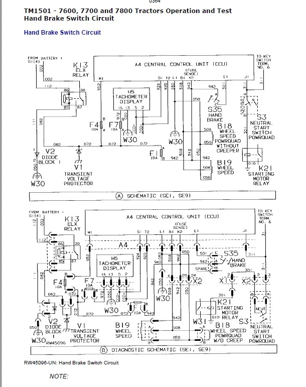
Hand Brake Switch Circuit 515
Using CCU Diagnostic Mode
Access On-Board CCU Diagnostic Mode
Address 5 Wheel Speed and True Ground Speed
Address 6 Brake Switches
Sensor Excitation Circuit 518
Sensor Excitation Detection Circuit 520
Using CCU Diagnostic Mode
Access On-Board CCU Diagnostic Mode
Address 14 Hydraulic Oil Filter Switch, and Sensor Excitation Fuse
CCD Communication Line 522
Voltage Checks 523
Component Tests
CCD Circuit Voltage (CCT 924 and 925)
Check CCD Circuit
CCD Circuit Check
Possible Causes
Check for Short or Grounded Circuit
Engine Hours Circuit 526
Engine Hours and Engine Starts 527
Using CCU Diagnostic Mode
Access On-Board CCU Diagnostic Mode
Address 4 Engine Speed and PTO Speed
Display Modules Circuit Schematic 529
Display Modules Circuit Diagnostic Schematic 530
Display Modules Circuit Operational Information 531
Tachometer Input Output Signals 533
Check Tachometer Circuit
Tachometer and Tachometer Circuit Check
Performance Monitor Operational Information 535
Performance Monitor Features 536
Performance Monitor Normal Operating Mode 537
Performance Monitor Set Mode 544
Performance Monitor Input Output Signals 549
Control Modules Diagnostic Schematic 550
20 Calibration and References
CCU Addresses 551
Accessing Tachometer Modes 552
CCU Modes/Addresses Navigational Flow Chart 553
Accessing CCU Calibration and Diagnostic Addresses
Preliminary Check
Accessible Addresses
CCU Calibration Procedure
Select Diagnostic Mode
Select CCU
Accessing CCU Diagnostic Mode
Check Stored Codes
Engine Pulses Per Revolution
Rear PTO Pulses Per Revolution
MFWD Enable/Disable
Clutch Cooling Enable/Disable
Display Units
Warning Flasher Operation
Diagnostic Storage Operation
Enable Rear Fender Turn Signals
Rear PTO Configuration
Front PTO Configuration
Emergency Steering
Fuel Sender
Wheel Rolling Radius
Transmission Pulses Per Axle Revolution
True Vehicle Speed Calibration
Current Vehicle Model Number
Current Vehicle Serial Number
CCU “Read Only” Addresses 571
CCU On-Board Diagnostic Procedure
Select Diagnostic Mode
Select CCU
Accessing CCU Diagnostic Mode
Check Stored Codes
Enter System Diagnostic “Beep” Mode Address “02”
Enter System Diagnostic “Beep” Mode Address “03”
Circuit Address Numbers 575
Operate Right Turn Signal
Address 4 Engine Speed and PTO Speed
Address 5 Wheel Speed and True Ground Speed
Address 6 Brake Switches
Address 7 Clutch, Neutral and Differential Lock Switches
Address 8 MFWD Switch
Address 9 Rear PTO Switch
Address 10 Front PTO Sense Lines
Address 11 Seat Switch
Address 12 Transmission Oil Pressure, Transmission Oil Filter and Air Filter Restriction
Address 13 Engine Oil Pressure
Address 14 Hydraulic Oil Filter Switch, and Sensor Excitation Fuse
Address 15 Wiper Time Delay Switch
Address 16 Fuel Level Sender
Address 17 Hydraulic Oil Temperature Sender
Address 18 Engine Coolant Temperature Sender
Address 19 Warning Lights Switch
Address Numbers “20” through “99” 586
CCU Non-Diagnostic “Read Only” Addresses 587
CCU Non-Diagnostic Read Only Addresses
Select Diagnostic Mode
Select CCU
Accessing CCU Diagnostic Mode
Check Stored Codes
System Voltage
Hydraulic Oil Temperature
Engine Coolant Temperature
Tractor Engine Start Count
Tractor Elapsed Engine Hours
Current Wheel Speed
Current True Vehicle Speed
CCU Part Number
CCU Serial Number
CCU Program Part Number
CCU Program Version Number
CCU End-of-Line (EOL) Part Number
CCU End-of-Line (EOL) Version Number
Original Vehicle Model Number
Original Vehicle Serial Number
Performance Monitor Calibration and Diagnostic Tool 599
Performance Monitor Calibration Diagnostics
Access Performance Monitor
Access Calibration Mode
Address 20
Address 21
Address 22
Address 23
Addresses 60 and 61
Addresses 92 and 93
Addresses 94 and 95
Using Performance Monitor as Remote Diagnostic/Calibration Device
Enter Performance Monitor Select Mode
Preview Available Devices
Access Diagnostic Mode and Address
Device Addresses
Calibrating Radar and Wheel Speed Sensors 605
Wheel Rolling Circumference and Percent Slip Zeroing 606
Battery Specifications 607
Battery Operation 608
Check Battery Electrolyte Level and Terminals 609
Procedure for Testing Batteries 611
Diagnose Battery Malfunctions 612
Using a Booster Battery or Battery Charger 613
250 Power Shift Transmission
05 Operational Checks
Before You Start 614
Operational Checks
Recall PCU Codes
Hydraulic Oil Temperature Check
Exit Diagnostic Mode
Neutral to Gear Engagement and Modulation Check
Forward to Reverse (Shuttle Shift) Modulation Check
Gear to Gear Modulation Check
Clutch Modulation With Pedal
C1-C2 Traction Clutch Check
Clutch Engagement Check
Differential Lock Operational Check
MFWD Operational Check
PTO Operational Check
10 Power Shift Transmission Diagnosis
Use Step-by-Step Hydraulic Diagnostic Charts 618
Special or Essential Tools 619
Service Equipment and Tools 621
Other Material 622
Transmission Cooler Flow Check 623
System and Lube Pressure Check 624
MFWD Clutch Element Leak Check 625
Avoid High-Pressure Fluids 626
Adjust for Correct Pressure and Temperature References 627
Observe Safety Precautions 628
PCU Operation 629
Gear Number Display 630
Gear/Element Combinations 631
PCU Diagnostic Addresses 632
How to Enter Diagnostic Address 633
How to Display and Clear Stored Diagnostic Codes (Address 1) 634
PCU Addresses 635
PCU Diagnostic Codes 636
Operating Diagnostic Beep Addresses 02 13 639
Accessing Tachometer Addresses 640
Come-Home Feature and Operation 642
Transmission Calibration Procedure 644
Transmission
Transmission Calibration Procedure
Error Messages 647
Calibration Errors 649
Shortened Diagnostic Procedure 650
Isolating Transmission Problems 651
Major System Checks 652
Power Shift Transmission Record Sheet 653
Power Shift Preliminary Checks
Preliminary Checks
Recall of CCU Codes
Recall of PCU Codes
Electronic Control Operation
Transmission Filter Check
Driving Check
Causes for 3 4 Seconds of Motion
Causes for No Tractor Motion
Install Test Equipment
Preliminary System and Lube Pressure Checks
Transmission Pump Suction Air Leak Check
Solenoid Valve Operational Check
Causes for No Pressure Drop for Certain Elements
Check for Stuck Shift Valve
Causes for No Tractor Motion
Heat Transmission Hydraulic Oil
Differential Lock Leak Check
Causes for Excessive Leakage
PTO Leak Check
PTO Element Leak Check
Causes for Excessive Leakage
MFWD Leak Check
MFWD Clutch Element Leak Check
Causes for Excessive Leakage
Element Leak Check at PCU Address 20
Causes for Tractor Movement
Element Leak Check (Continued)
Pressure Check
Causes for Excessive Element Leakage
Clutch Cooling Solenoid Check
Causes for Improper Pressure Charge
Shift Solenoid Pressure Cycle Check
Shift Solenoid Duty Cycle Check (Continued)
Causes for Faulty Voltage Readings
Inspect Solenoid Valve
Transmission Lube Pressure Check
Transmission Cooler Flow Check
Cooler Relief Valve Check
Causes for Cooler Relief Setting Out of Spec
Transmission Pump/Cooler Flow Check
Causes for Low Pump/Cooler Flow
Causes for Low Lube Pressure With Normal Pump Flow
Transmission System Pressure Check
Adjust System Pressure Regulating Valve
Transmission Air Pump Vacuum Check
Summary of Transmission Testing
Test Procedure No. 1 682
Test Procedure No. 1 Diagnostics
Lube Relief Valve Check
Test Procedure No. 2 684
Test Procedure No. 2 Diagnostics
PST Transmission Pump Suction Air Leak Check
Test Procedure No. 3 685
C1, C2 Clutch Drag and Element Slip Checks
C1 Clutch Drag Check
C2 Clutch Drag Check
Excessive Clutch Drag Check
Element Slippage Check
20 Theory of Operation
Guide to Power Shift Transmission Theory 687
PST Transmission (Components) 688
Planetary Operation 690
Test Port/Sensor Location 693
Element Engagement Chart 694
Hydraulic Control of Transmission 695
Electro-Hydraulic (FEMA) Valve 696
Reduction Gear Box 698
Power Shift Transmission Schematic (Component Identification) 699
255 PowrQuad Transmission
05 Transmission Operational Checks
Before You Start 701
Transmission Operational Checks
Recall Codes
Neutral to Gear Modulation Check
Forward to Reverse Modulation Check
Gear to Gear Modulation Check
Range Box Check
Clutch Modulation With Clutch Pedal
Transmission Creep Check
Clutch Engagement Check
Differential Lock Operational Check
MFWD Operational Check
PTO Operational Check (Front or Rear)
10 Transmission Diagnosis
Use Step-By-Step Hydraulic Diagnostic Charts 705
Special or Essential Tools 706
Service Equipment and Tools 708
Other Material 709
Transmission Cooler Flow Check 710
System and Lube Pressure Check 711
MFWD Clutch Element Leak Check 712
Avoid High-Pressure Fluids 713
Adjust for Correct Pressure and Temperature References
Observe Safety Precautions
Shortened Diagnostic Procedure
Major System Checks
Diagnostic Steps
Preliminary Checks
Recall Codes
Transmission Filter Check
Install Test Equipment
Driving and Preliminary Pressure Checks
Tractor Does Not Move and No System Pressure
Tractor Does Not Move Forward or Reverse
Tractor Stops Moving After Shifting
Tractor Missing Certain Speeds
Heating Transmission Hydraulic Oil
Transmission Speed Element Leak Check
Transmission Speed Circuit Pressure Check
Transmission Speed Circuit Leakage Check
Forward Clutch Leak Check
Forward Clutch Circuit Pressure Check
Control Valve Housing Leakage Points Check
Reverse Brake Leak Check
Reverse Brake Circuit Pressure Check
Reverse Brake (Continued)
Differential Lock Circuit Leak Check
Excessive Leakage:
PTO Circuit Leak Check
PTO Circuit Leak Check (Continued)
Excessive PTO Leakage
MFWD Circuit Leak Check
MFWD Clutch Circuit Leak Check
Excessive Leakage
Transmission Lube Pressure Check
Connect Flow Meter for Oil Cooler Flow Check
Cooler Relief Valve Check
Cooler Relief Setting Out of Specification
Transmission Pump/Cooling Flow Check
Low Pump/Cooler Flow
Low Lube Pressure With Normal Pump Flow
Transmission System Pressure Check
Adjust System Pressure Regulating Valve
Clutch Cooling Circuit Check
Improper Clutch Cooling Operation
Transmission Air Pump Vacuum Check
Summary of Transmission Testing
Additional Trouble Shooting Information
Lube Relief Valve Stuck Open
Transmission Pump Air Leak Check
Clutch and Brake Element Air Leak Check Using a Blow Gun
Transmission Control Valve Housing Gasket
Transmission Slippage
PTO Clutch Drag
Hydraulics Fluid Over-Heating
Forward Clutch and Reverse Brake Pressure Chart
20 Theory of Operation
Guide To Transmission Theory
Transmission
Transmission Schematic Early Version (Component Identification)
Transmission Schematic Later Version
Planetary Operation
Test Port and Sensor Identification
Air Pump
Transmission Oil Pump
Clutch Oil Manifold
Reverse Brake Housing
Filter Relief Valve
Pressure Regulating Valve
Speed Control Circuit
EOV Circuit
Speed Modulator
Shifting From One Speed to Another Using the Speed Control Lever
Speed Lever Moved from Neutral to Second Forward or Second Reverse
FWD-REV Modulation
Shift Lever Moved From Neutral to Forward or Reverse
Shift Lever Moved From Forward or Reverse to Neutral:
Traction Element Cooling Oil Components
Oil Cooler System
Creeper Transmission Operation
Range Box
256 Drive Systems
05 Operational Checks
Drive Systems
Operational Checks
Differential Lock Operational Check
Front and Rear PTO Operational Check
MFWD Operational Check
10 Drive System Diagnosis
Special or Essential Tools 714
Avoid High-Pressure Fluids 715
Differential Lock Leak Check 716
Differential Lock Leak Check
Differential Lock Leak Check
Excessive Leakage
Rear Differential Diagnosis 717
PTO Checks 718
Rear PTO Diagnostics
Rear PTO Leak Check
Rear PTO Element Leak Check
Excessive Leakage
Rear PTO Modulating Valve Check
Front PTO Diagnostics
Front PTO Check
Low Pressure
Using MFWD Step By Step Test Procedure 723
Observe Service Precaution 724
MFWD Diagnostic Procedures
MFWD Symbol Lamp Check
MFWD Symbol Not On
MFWD Dash Symbol and CCU Fault Code Check
Code 86 and MFWD Symbol Flashing Check
Code 72, PTO Symbol, and MFWD Symbol Steady Check
MFWD Operational Check
Primary MFWD Solenoid Electrical Operational Check
Secondary MFWD Solenoid Electrical Operational Check
Primary MFWD Solenoid Hydraulic Operational Check
MFWD Clutch Release Pressure Check
Left Wheel Does Not Rotate
Secondary MFWD Solenoid Hydraulic Operational Check
MFWD Clutch Port Pressure Check
Wheel Rotates with MFWD Switch at “ON”
MFWD Clutch Leak Check
MFWD Clutch Element Leak Check
Excessive Leakage
MFWD Clutch Slippage Check (Optional)
Check Torque of MFWD Clutch
MFWD Switch and Solenoid Check at Auto Position
MFWD Symbol Off
Strong Magnetic Field in Auto
MFWD Solenoid and Clutch Operational Check Below 14km/h (8.5 mph):
Incorrect MFWD Symbol or Solenoid Operation
MFWD Solenoid and Clutch Operational Check Above 14 KM/H (8.5 mph):
Incorrect MFWD Solenoid and/or Symbol Operation
MFWD Electrical Schematic 736
20 Adjustments
MFWD Brake Pedal Switch Adjustment 737
25 Theory of Operation
Differential Lock Operation 738
Rear Differential Operation 739
Final Drive Operation 740
PTO Modulating Valve Operation 741
Rear PTO 743
Rear PTO Clutch and Brake Operation 744
Dual Speed PTO 1000 RPM Engagement 745
Dual Speed PTO 540 RPM Engagement 746
Two-Speed Shiftable PTO 1000 RPM Engagement 747
Two-Speed Shiftable PTO 540 RPM Engagement 748
Front PTO 749
Front PTO Operation 750
MFWD Clutch Operation 751
MFWD Axle Operation 752
MFWD Differential Operation Limited Slip 753
260 Steering and Brakes
15 Tests and Adjustments
Brake Operational Test 754
Reference
Brake Operational Test
20 Theory of Operation
Steering System Operation 755
Hydraulic System Primary Circuit Steering and Brakes 756
Steering Control Valve Assembly 758
Cutaway View of Steering Valve 760
Gerotor Operation 761
Neutral Steering 762
Right-Turn Steering 764
Emergency Steering 766
Gerotor Operation 768
Ground-Driven Auxiliary Steering Pump 769
Normal Steering Mode 770
Brake Pistons, Plates and Disks Operation 775
Brake Released 776
Brake Modulation 778
Brake Engaging 779
Manual Braking Prefill 782
Manual Braking Engaging 784
270 Hydraulic System
05 Operational Checks
Before You Start 786
Hydraulic System Operational Checks
Hydraulic System Load Check
Hydraulic Operational Check
Hitch
Driving Checks
10 Hydraulic System Diagnosis
Use Step-by-Step Hydraulic Diagnostic Charts 790
Special or Essential Tools 791
Service Equipment and Tools 793
Hydraulic Filter Check 794
Main Pump Inlet Check 795
Primary Circuit Pressure Check 796
Hydraulic Pump Flow Check 797
Pump Load-Sense Pressure Check 798
Main Pump Flow Check 799
Avoid High-Pressure Fluids 800
Adjust for Correct Pressure and Temperature References 801
Observe Safety Precautions 802
Heating Hydraulic Oil 803
Navigational Flow Chart 804
Major System Checks Hydraulics 805
Hydraulic
Preliminary Checks
Recall CCU Codes
Hydraulic Filter Check
Install Test Equipment
Preliminary Main Pump Inlet Pressure Check
Man Pump Standby and Stall Pressure Check
Pump Pressure Slowly Decreasing
Pump Pressure Above Standby or Near Stall
Pump Pressure at or Nearby Standby
Pump Pressure at Zero
Severe Pressure Pulsation at High Pressure or Noisy Pump
Hydraulic System Leakage Check
Hydraulic System Leakage Check Continued
Excessive Leakage
Main Pump Inlet Pressure Check
Charge Pump Suction Air Leak Check
Air in Oil
Low Pump Inlet Pressure
High Pump Inlet Pressure
Main Pump Stall Pressure Check
Pump Outlet Pressure Adjustment
Main Pump Inlet Pressure Check (Pump at Full Flow)
Low Pump Inlet Pressure
Pump Load Sense Circuit
High Neutral Pump Load-Sense Pressure
Low Neutral Pump Load-Sense Pressure
Pump Load-Sense Valve Differential Pressure Check (Quick Check)
Primary Circuit Pressure Check
Low Primary Stall Pressure
Primary Pressure Adjustment
Priority Valve Operational Pressure Check
Optional Priority Valve Differential Pressure Check
Incorrect Differential Priority Valve Pressure
Main Pump Flow Check
Main Pump Flow Check Continued
Main Pump Flow Check Continued
Main Pump Flow Check Continued
Pump Load-Sense Differential Pressure Check
Pump Load-Sense Valve Adjustment
Summary Of Hydraulic Testing
Additional Troubleshooting Information 833
Hydraulic System Response to a Missing Shuttle Check Valve 834
SCV and Coupler Leak Test 836
Three-Position SCV Lever Kick Out Adjustment 837
Bleeding Load-Sense and Hydraulic Pressure Circuits 839
Electro-Hydraulic Depth Control (EHDC) Diagnosis 840
EHDC Checkout
Hitch Operational Check
Hitch Calibration
EHDC System Check
Hitch Troubleshooting Tips 841
Come Home Feature 842
Component Test Specifications 843
HCU Hardware and Software Information 844
Hitch Circuit Diagnosis 845
Test Procedure No. 1 HCU 847
HCU Diagnostic Code Numbers
HCU Diagnostic Code Numbers
Clear Codes
Diagnostic Codes 848
HCU Diagnostic Code Numbers 849
Test Procedure No. 2 850
HCU Circuit Diagnostic “Beep” Addresses 851
System Diagnostic (Beep) Mode (HCU)
Access System Diagnostic (Beep) Mode (02)
Operate Hitch Controls
Tractor Off Test
Test Procedure No. 3 853
Hitch Raise/Lower Rocker Switch Test
Hitch Raise/Lower Rocker Test
Hitch Raise/Lower Rocker Switch (Raise)
Hitch Raise/Lower Rocker Switch (Lower)
Test Switch Circuit
Test Circuit Lower Function
Test Circuit Raise Function
Check Harness Continuity
Test Procedure No. 4 856
Auxiliary Input Circuit Test
Determine HCU Mode
Auxiliary Input Test
Check Harness Connector
Auxiliary Input Test
Test HCU in EHDC Mode
EHDC Mode
EHDC Mode (Continued)
Test Procedure No. 5 860
Draft Sensor Test
Hitch Draft Sensor
Draft Voltage
Draft Voltage
Voltage Reading is Less Than 0.65 Volts or More Than 0.90 Volts
Voltage Reading is More Than 4.50 Volts or Less Than 3.95 Volts
Voltage Reading Out of Range
Test Procedure No. 6 863
Hitch/Load/Depth Control Potentiometer Test
Minimum Low Sensitivity (CCW)
Maximum Load Sensitivity (CW)
Test Procedure No. 7 865
Hitch Control Lever Potentiometer Test
Hitch Raise Command Voltage
Hitch Lower Command Voltage
Test Procedure No. 8 867
Hitch Position Feedback Sensor Test
Hitch Control Lever Forward
Voltage Difference
Test Procedure No. 9 869
Hitch Raise Limit Control Potentiometer Test
Raise Limit Control Potentiometer Voltage (CCW)
Raise Limit Control Potentiometer Voltage (CW)
Test Procedure No. 10 871
Hitch Rate-of-Drop Control Potentiometer Test
Rate-of-Drop Control Potentiometer Voltage (CCW)
Raise Limit Control Potentiometer Voltage (CW)
Test Procedure No. 11 873
External Raise/Lower Switch Test (Raise Command)
Switch Centered (Off)
Switch Up (Hitch Raise)
Switch Centered (Off)
Switch Down (Hitch Lower)
Test Procedure No. 12 875
External Raise/Lower Switch Test (Lower Command)
Switch Centered (Off)
Switch Down (Hitch Lower)
Switch Centered (Off)
Switch Up (Hitch Raise)
Test Procedure No. 13 877
Sensor Supply Voltage Test
Sensor Supply Voltage
Check Harness
Test Procedure No. 14 879
Test Procedure No. 15 880
Test Procedure No. 16 881
Test Procedure No. 17 882
Hitch Valve Commands Test
Recall Codes
Check Solenoid Coil Resistance
Check Harness Circuits
Check Harness for Shorts
Clean Valve Seats
Adjust Hitch Valve 885
Hitch Valve Adjustment
Check Return Valve Setting
Adjust Pressure Valve Setting
Check Pressure Valve Setting
Adjust Return Valve Setting
Calibrate Hitch
Test Procedure No. 18 888
System Voltage Test
Preliminary Check
Operate the Right Turn Signal
Check Sensor Supply Voltage
Check Battery Voltage
Test Procedure No. 19 890
Hydraulic Oil Temperature Readout
Hydraulic Oil Temperature Readout
Test Procedure No. 20 891
Test Procedure No. 21 892
Improper Calibration
Improper Calibration
Test Procedure No. 22 893
Failed Calibration
Failed Calibration
Test Procedure No. 23 894
Circuit Fault During Calibration
Circuit Fault During Calibration 239
(LHP) Tests 895
ROW-TRAK
Test Procedure No. 1
LHP Diagnostic Code Numbers
Clear Codes
Operate Controls
Diagnostic Codes 897
LHP Diagnostic Code Numbers 898
Test Procedure No. 2 899
LHP Circuit Diagnostic “Beep” Addresses 900
System Diagnostic (Beep) Mode (LHP)
Access System Diagnostic (Beep) Mode (02)
Controls
Tractor Off Test
Test Procedure No. 3 902
Test Procedure No. 4 903
Test Procedure No. 5 904
Pivot Angle Sensor Test
Pivot Angle Sensor Voltage (Coupler Pivot Left)
Pivot Angle Sensor Voltage (Coupler Pivot Right)
Sensor Voltage Range
Test Procedure No. 6 907
Row Sensor Test
Row Sensor Voltage (Sensor Centered)
Row Sensor Voltage (Sensor Full Right)
Row Sensor Voltage (Sensor Full Left)
Row Sensor Voltage Range
Test Procedure No. 7 910
Test Procedure No. 8 911
Operation Mode
Operating Mode (Mode Select Switch)
Test Procedure No. 9 912
Position Control Test
Position Control Command (Full Left CCW)
Position Control Command (Full Right CW)
Test Procedure No. 10 914
Response Rate Control Test
Response Rate Control Command (Full Left CCW)
Response Rate Control Command (Full Right CW)
Test Procedure No. 11 916
Hitch Vertical Position Test
Hitch Lever Command (Transport Lock)
Hitch Lever Command (Full Down)
Check Crop Sensor Action
Test Procedure No. 12 918
Test Procedure No. 13 919
Sensor Supply Voltage Test
Sensor Supply Voltage
Check Harness
Test Procedure No. 14 920
Row Sensor Up/Down Status Test
Row Sensor Status
Test Procedure No. 15 921
Tractor Model Number Check
Tractor Model Number
Test Procedure No. 16 922
Position Control Center Adjustment
Check Position Control Command (Full Left CCW)
Check Position Control Command (Full Right CW)
Check Position Control Command (Centered)
Test Procedure No. 17 924
Valve Commands Test
No Valve Command
CCW Rotation Command
CW Rotation Command
Operate Pivot Coupler
Tests are OK But Operation is Not Smooth
Test Procedure No. 18 927
System Voltage Test
Access Diagnostic Mode
Access LHP
Select LHP
Access LHP/18
Check Terminals
Test Procedure No. 19 930
Hydraulic Oil Temperature Readout
Test Procedure No. 20 931
Test Procedure No. 21 932
Improper Calibration
Test Procedure No. 22 933
Failed Calibration
Test Procedure No. 23 934
Circuit Fault During Calibration
Test Procedure No. 24 935
CCD Circuit Fault
Hitch Control Circuit Schematic 936
Hitch Control Circuit Diagnostic Schematic 938
15 Calibration and Adjustments
HCU Addresses 940
Calibration
Hitch Calibration
Set Hitch Controls for Calibration 941
Calibration and Adjustments
Select Diagnostic Mode
Select HCU
Access HCU Diagnostic Mode
Check Stored Codes
Check Hydraulic Oil Temperature
Enter Hitch Calibration Mode
Purge Air from Hitch Hydraulic Circuit
Prepare to Calibrate Return Valve
Calibrate Raise Limit Control
Set Estimate for Return Valve Preload
Prepare to Set Return Valve Preload
Calibrate Return Valve Preload
Prepare to Calibrate Pressure Valve Preload
Set Estimate for Pressure Valve Preload
Prepare to Set Pressure Valve Preload
Calibrate Pressure Valve Preload
Calibrate Lift Cylinder Fill Volume Number
Check Rate-of-Drop Control Calibration
Check Load/Depth Control Calibration
Calibrate Draft Sensor
Set Draft Sensor Zero
Prepare Hitch for Position Feedback Sensor Check
Check Hysteresis of Hitch Position Feedback Sensor During Raise
Verify Raise Function of External Raise/Lower Switch
Check Hysteresis of Hitch Position Feedback Sensor During Lower
Store Calibration Data in HCU
LHP Addresses 955
LHP Calibration
LHP Calibration
Prepare System for Calibration 956
LHP Calibration
Select Diagnostic Mode
Access LHP
Select LHP
Check Hydraulic Oil Temperature
Calibration Mode
Purge Air from Circuit, Calibrate Position Control and Actuator Position Sensor
Prepare to Calibrate Extend Valve Preload
Check Response Rate Control
Set Extend Valve Preload Estimate
Prepare to Set Extend Valve Preload
Calibrate Extend Valve Preload
Prepare to Calibrate Retract Valve Preload
Set Retract Valve Preload Estimate
Prepare to Set Retract Valve Preload
Calibrate Retract Valve Preload
Set Valve Gain
Store Calibration Data in LHP
LHP Hydraulic Checks
20 Theory of Operation
Hydraulic System Components 967
Hydraulic System Schematic 968
Hydraulic System Schematic (Component Identification) 969
Pump Operation 970
Hydraulic System Charge Circuit Schematic 977
Hydraulic Filter Operation 979
Charge Pump 981
Hydraulic System Secondary Circuit (Component Identification) 986
Priority Valve 988
Neutral at Start Up 989
Neutral 990
Steering Operation 992
Steering Relief 994
Steering Returned to Neutral 995
High Pressure Demand from Secondary 996
Two-Position Selective Control Valve Neutral 997
Two-Position Selective Control Valve Extend 999
Two-Position Selective Control Valve Retract 1001
Two-Position Selective Control Valve Float 1002
Three-Position Selective Control Valve Operation Neutral 1003
Three-Position Selective Control Valve Operation Extend 1005
Three-Position Selective Control Valve Operation Retract 1007
Three-Position Selective Control Valve Operation Float 1009
ISO Coupler Closed 1011
ISO Coupler Coupling 1012
ISO Coupler Opening 1013
ISO Coupler Uncoupling 1014
Hitch Control Valve 1015
Pressure and Return Solenoid Valves 1016
Hitch Control Valve Neutral Position 1017
Pressure Compensator Valve 1018
Load Check Valve 1019
Surge Relief Valve 1020
Hitch Load-Sense Check Valve 1021
Hitch Operation Raised 1022
Hitch Operation Stopped 1023
Hitch Operation Lower 1024
Hitch Operation Full Lower 1025
Three Point Hitch Hydraulic Operation 1026
Hitch Controls 1027
Electro-Hydraulic Hitch Circuit 1028
Electro-Hydraulic Hitch Sensor Locations 1030
Hitch Control Unit (HCU) 1031
Operator Controls 1032
Hitch Control Lever 1033
Load/Depth Control Potentiometer 1034
Rate-of-Drop Control Potentiometer 1035
Raise Limit Control Potentiometer 1036
Console Raise/Lower Rocker Switch 1037
External Raise/Lower Switch 1038
Hitch Sensing Devices 1039
Hitch Position Feedback Sensor 1040
Load/Draft Sensor 1041
Remote Lift Assist (RLA) and Electro-Hydraulic Depth Control (EHDC) Features 1042
Remote Lift Assist (RLA) Mode 1043
Electro-Hydraulic Depth Control (EHDC) Optional 1044
Electro-Hydraulic Depth Control (EHDC) Mode 1045
Wiring Harnesses 1046
Hitch Harnesses 1047
290 Operator Station
05 Air Conditioning Operational Checks
Before You Start 1049
A/C System Operational Checks
Engine Off Checks
Blower Motor Check
Air Distribution Check
Engine Running Checks
Temperature Drop Check
Check Heater Valve Operation
Results of Operational Check
10 Air Conditioning System Diagnosis
Service Equipment and Tools 1052
Specifications 1053
Air Conditioning System Diagnosis
Compressor Clutch Engagement Check
Static Pressure Check
Circulator and Pressurizer Motor Check
Isolate Malfunction
Check Voltage and Continuity
Check Fuse F18
Reason For Failed Fuse
Loss of Battery Power Before Fuse
Loss of Battery Power After Fuse
Check Air Outlet Distribution
System Cooling Check
Temperature Drop Check
Check Heater Valve Operation
Install Test Equipment
System Static Pressure Check
No Gauge Pressure
Low Pressure
Clutch Cycle Check
Causes of Frequent Clutch Cycling
Sight Glass Check
Leak Check System
Add Refrigerant
System Pressure Check
Suction Pressure Low, Normal or High and Discharge Pressure High With Bubbles
Suction Pressure High and Discharge Pressure Low
Suction Pressure Normal or High and Discharge Pressure High Without Bubbles
Recharge System
Check Expansion Valve Operation
Pressure Does Not Change
Suction Low or Vacuum and Discharge Normal or Low
Defrost Evaporator
Temperature Drop Check
Engine Coolant Leak Check
Engine Coolant Not Shut Off
Excessive Air Leakage From Cab
Possible Causes For Lack of Cooling Are
Internal Line Restriction Check
Poor Cooling
Refrigerant Loss Switch (Low Pressure) Check
High Pressure Switch Check
De-Icing Switch Check
System Testing Summary
Remove Moisture From System
Air Conditioning System Components 1074
Air Conditioning System 1075
AQS and Convenience Outlet Circuits Schematic (SE3) 1076
AQS and Convenience Outlet Circuits Diagnostic Schematic (SE3) 1077
25 Air Conditioning Theory of Operation
Refrigerant 1079
Air Conditioning System Air Flow 1080
Air Conditioning System Cycle 1081
Compressor 1083
Condenser 1084
Receiver-Dryer 1085
Expansion Valve 1086
De-Icing Switch 1087
Evaporator 1088
Temperature Control Knob 1089
Compressor On/Off Switch 1090
High and Low Pressure Switches 1091
299 Dealer Fabricated Tools
05 Dealer Fabricated Tools
DFRW2 Needle Valve Test Hose Assembly 1092
DFRW51 Electronic Circuit Load Tester 1093
DFRW85 Reverse Brake Test Plate 1094
DFRW86 Spool Holding Tool 1095
DFRW60 – DFRW61 – DFRW62 Extension Harnesses 1096
DFRW63 – DFRW64 – DFRW65 – DFRW66 – DFRW81 Tap-Out Harnesses 1097
IMAGES PREVIEW OF THE MANUAL:
JOHN DEERE TRACTORS 7600 7700 7800 DIAGNOSTIC &TEST MANUAL – PDF DOWNLOAD:
PLEASE NOTE:
- This is the same manual used by the dealers to diagnose and troubleshoot your vehicle
- You will be directed to the download page as soon as the purchase is completed. The whole payment and downloading process will take anywhere between 2-5 minutes
- Need any other service / repair / parts manual, please feel free to contact [email protected] . We still have 50,000 manuals unlisted
S.V