Kaeser FSD Sigma Control 2 Service Manual PDF
Original price was: $95.00.$16.95Current price is: $16.95.
Download the official Kaeser FSD service manual PDF for screw compressors with Sigma Control 2. This Sigma Control 2 screw compressor repair guide includes detailed Kaeser compressor maintenance instructions, FSD Sigma Control troubleshooting manual, installation, fault rectification, and safety guidelines for efficient operation and repairs.
Description
Kaeser FSD Sigma Control 2 Service Manual PDF DOWNLOAD
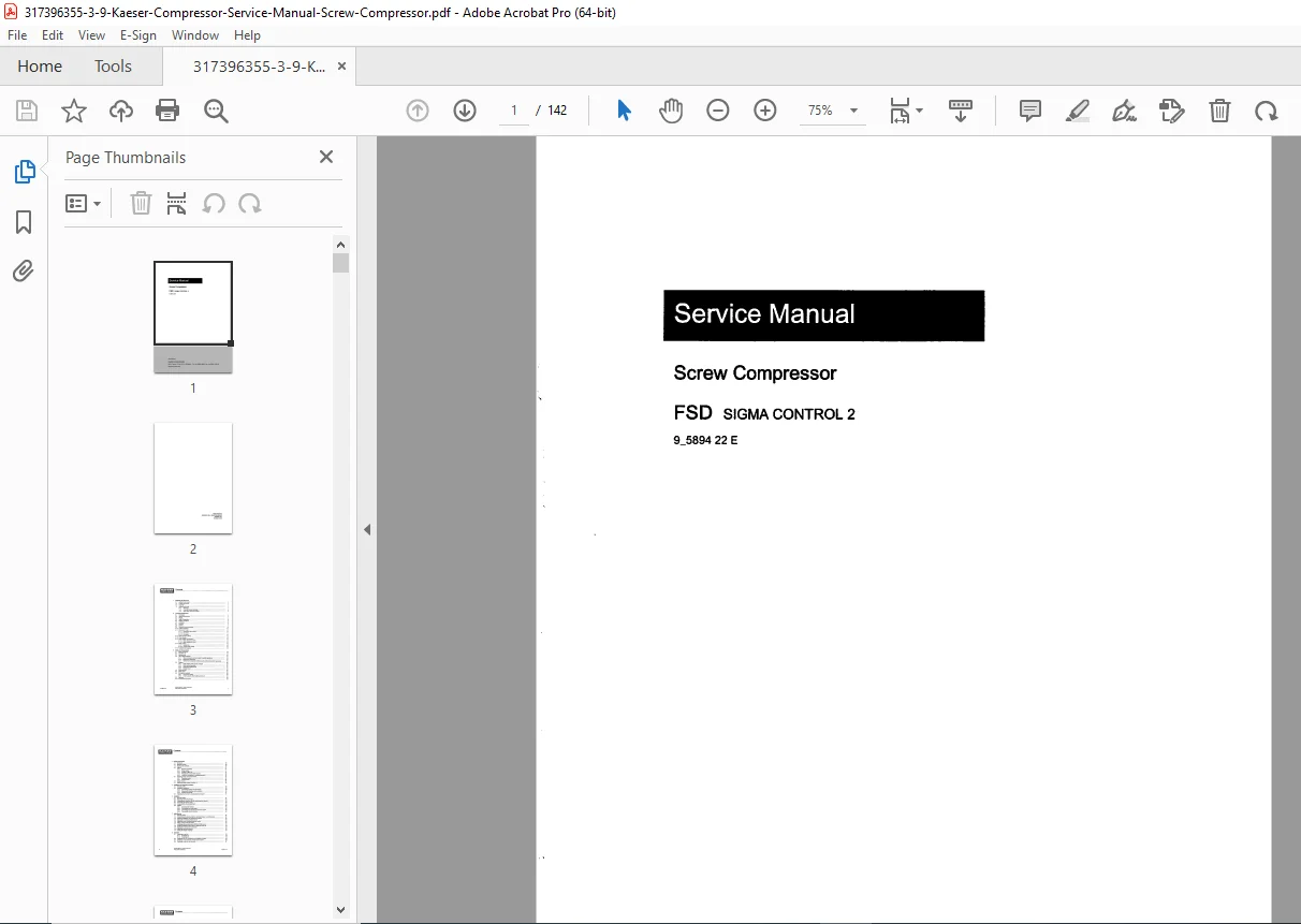
Description: This comprehensive Kaeser FSD service manual PDF download is an essential resource for technicians servicing Kaeser screw compressors equipped with Sigma Control 2. Published under code 9_5894 22 E by Kaeser Kompressoren, it provides in-depth coverage of technical specifications, safety protocols, design functions, installation, initial start-up, operation, maintenance, and decommissioning, ensuring compliance and optimal performance. With diagrams, flow charts, and troubleshooting tables, this manual supports safe handling and preventive measures for FSD series machines.
The guide emphasizes safety devices, proper cooling oil management, and adherence to regulations, making it a reliable Sigma Control 2 screw compressor repair guide for addressing faults and performing regular service tasks.
File Details:
- Manual Name: Service Manual Screw Compressor FSD SIGMA CONTROL 2
- Models Covered: FSD series with Sigma Control 2
- Year: Latest Edition
- Manual PDF Quality: High-quality scanned document with clear text, illustrations, and diagrams
- No. of Pages: 142
Table of Contents:
- 1 Regarding this document
- 1.1 Using this document
- 1.2 Further documents
- 1.3 Copyright
- 1.4 Symbols and labels
- 1.4.1 Warnings
- 1.4.2 Potential damage warnings
- 1.4.3 Other alerts and their symbols
- 2 Technical Specifications
- 2.1 Nameplate
- 2.2 Optional accessories
- 2.3 Weight
- 2.4 Select Temperature
- 2.5 Ambient conditions
- 2.6 Ventilation
- 2.7 Pressure
- 2.8 Delivery
- 2.9 Cooling oil recommendation
- 2.10 Cooling oil charge
- 2.11 Motors and Power
- 2.11.1 Compressor drive motor
- 2.11.2 Fan motor
- 2.11.3 Fan motor
- 2.12 Noise emission (dB(A))
- 2.13 Power Supply
- 2.14 Power supply specifications
- 2.14.1 Mains frequency: 50 Hz
- 2.14.2 Mains frequency: 60 Hz
- 2.15 Water cooling
- 2.15.1 Design data
- 2.15.2 Cooling water quality
- 2.16 Available heat capacity
- 3 Safety and Responsibility
- 3.1 Basic instructions
- 3.2 Specified use
- 3.3 Improper use
- 3.4 User’s Responsibilities
- 3.4.1 Observe statutory and universally accepted regulations
- 3.4.2 Determining personnel
- 3.4.3 Adherence to inspection schedules and accident prevention regulations
- 3.5 Dangers
- 3.5.1 Safely dealing with sources of danger
- 3.5.2 Safe machine operation
- 3.5.3 Organisational Measures
- 3.5.4 Danger Areas
- 3.6 Safety devices
- 3.7 Safety signs
- 3.8 Emergency situations
- 3.8.1 Correct fire fighting
- 3.8.2 Treating injuries from handling cooling oil
- 3.9 Warranty
- 3.10 Environment protection
- 4 Design and Function
- 4.1 Enclosure
- 4.2 Machine function
- 4.3 Floating relay contacts
- 4.4 Options
- 4.4.1 Machine mountings
- 4.4.2 Water-cooling
- 4.4.3 Cooling air filter mat
- 4.4.4 Prepared for external heat recovery
- 4.4.5 Control air connection for modulating control
- 4.5 Operating modes and control modes
- 4.5.1 Operating modes
- 4.5.2 Control modes
- 4.6 Safety Devices
- 4.7 Operating panel SIGMA CONTROL 2
- 5 Installation and Operating Conditions
- 5.1 Ensuring safety
- 5.2 Installation conditions
- 5.2.1 Determining location and clearances
- 5.2.2 Ensuring the machine room ventilation
- 5.2.3 Exhaust duct design
- 5.3 Operating the machine in a compressed air network
- 6 Installation
- 6.1 Ensuring safety
- 6.2 Reporting Transport Damage
- 6.3 Connecting the machine with the compressed air network
- 6.4 Connecting the power supply
- 6.5 Connecting the Condensate Drain
- 6.6 Options
- 6.6.1 Anchoring the machine
- 6.6.2 Connecting the cooling water
- 6.6.3 Connecting the external heat recovery system
- 6.6.4 Connecting external control air
- 7 Initial Start-up
- 7.1 Ensuring safety
- 7.2 Instructions to be observed before commissioning or re-commissioning
- 7.3 Checking installation and operating conditions
- 7.4 Setting the overload protection cut-out
- 7.5 Setting the motor overload protection switch
- 7.6 Filling cooling oil into the airend
- 7.7 Activating and deactivating the MODULATING control
- 7.8 Switching MODULATING control to external control air
- 7.9 Starting the machine for the first time
- 7.10 Setting the set point pressure
- 7.11 Setting the display language
- 8 Operation
- 8.1 Switching on and off
- 8.1.1 Switching on
- 8.1.2 Switching off
- 8.2 Switching off in an emergency and switching on again
- 8.3 Switching on and off from a remote control centre
- 8.4 Switching on and off with the clock
- 8.5 Interpreting operation messages
- 8.6 Acknowledging alarm and warning messages
- 8.1 Switching on and off
- 9 Fault Recognition and Rectification
- 9.1 Basic instructions
- 9.2 Other Faults
- 10 Maintenance
- 10.1 Ensuring safety
- 10.2 Following the maintenance plan
- 10.2.1 Logging maintenance work
- 10.2.2 Resetting maintenance interval counters
- 10.2.3 Regular maintenance tasks
- 10.2.4 Cooling oil: Change interval
- 10.2.5 Regular service tasks
- 10.3 Control cabinet: Clean or renew the filter mat
- 10.4 Cooler maintenance
- 10.5 Water-cooling Maintenance
- 10.6 Cleaning or Renewing the Cooling Air Filter Mat
- 10.7 Maintaining the heat recovery system
- 10.7.1 External heat recovery system
- 10.8 Changing the air filter
- 10.9 Motor maintenance
- 10.10 Checking the Coupling
- 10.11 Testing the pressure relief valve
- 10.12 Checking the overheating safety shutdown function
- 10.13 Checking the cooling oil level
- 10.14 Venting the machine (de-pressurising)
- 10.15 Replenishing the cooling oil
- 10.15.1 Venting the machine (de-pressurising)
- 10.15.2 Topping up with cooling oil and trial run
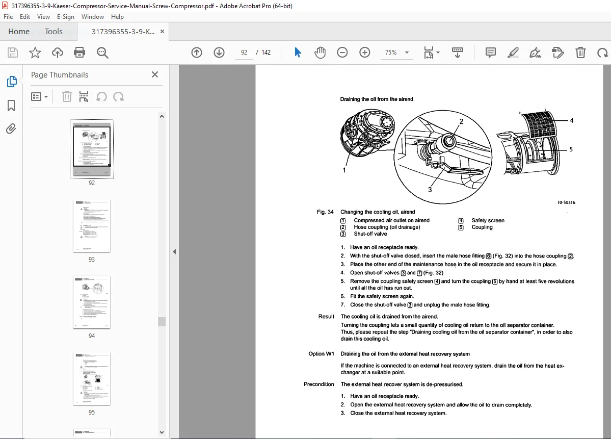
- 10.16 Changing the Cooling Oil
- 10.17 Changing the oil filter
- 10.18 Changing the oil separator cartridge
- 10.19 Condensate drainage maintenance
- 10.19.1 Checking condensate drainage
- 10.19.2 Cleaning the condensate drain
- 10.20 Assembling flexible pipe connections
- 10.21 Documenting maintenance and service work
- 11 Spares, Operating Materials, Service
- 11.1 Note the Nameplate
- 11.2 Ordering consumable parts and operating fluids/materials
- 11.3 KAESER AIR SERVICE
- 11.4 Service Addresses
- 11.5 Spare Parts for Service and Repair
- 12 Decommissioning, Storage and Transport
- 12.1 Putting Out of Operation
- 12.2 Packing
- 12.3 Storage
- 12.4 Transport
- 12.4.1 Safety
- 12.4.2 Transport with a forklift truck
- 12.4.3 Transport with a crane
- 12.5 Disposal
- 13 Annex
- 13.1 Pipeline and instrument flow diagram (P+1 diagram)
- 13.2 Pipeline and instrument flow diagram (P&I diagram) MODULATING control
- 13.3 Dimensional drawing
- 13.4 Electrical Diagram
No separate bookmarks or index are present; the detailed table of contents and lists of figures/tables serve as navigation aids.
This FSD Sigma Control troubleshooting manual is invaluable for diagnosing issues like faults and maintenance needs, making it a must-have Kaeser compressor maintenance instructions resource.
Equip yourself with this Sigma Control 2 screw compressor repair guide—download instantly for immediate access to professional-level diagnostics and keep your Kaeser FSD compressor running efficiently today!