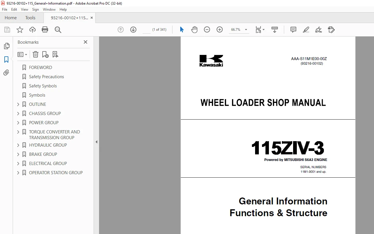
Kawasaki 115ZIV-3 WHEEL LOADER SHOP MANUAL AAA-S11M1E00-00Z – PDF DOWNLOAD
$28.95
Kawasaki 115ZIV-3 WHEEL LOADER SHOP MANUAL AAA-S11M1E00-00Z – PDF DOWNLOAD
(93216-00102)
SERIAL NUMBERS
11M1-9001 and up.
Powered by MITSUBISHI S6A3 ENGINE
AAA-S11M1E00-00Z
General Information
Functions & Structure
Description
Kawasaki 115ZIV-3 WHEEL LOADER SHOP MANUAL AAA-S11M1E00-00Z – PDF DOWNLOAD
FILE DETAILS:
Kawasaki 115ZIV-3 WHEEL LOADER SHOP MANUAL AAA-S11M1E00-00Z – PDF DOWNLOAD
Language :English
Pages :341
Downloadable : Yes
File Type : PDF
IMAGES PREVIEW OF THE MANUAL:
DESCRIPTION:
Kawasaki 115ZIV-3 WHEEL LOADER SHOP MANUAL AAA-S11M1E00-00Z – PDF DOWNLOAD
(93216-00102)
SERIAL NUMBERS
11M1-9001 and up.
Powered by MITSUBISHI S6A3 ENGINE
AAA-S11M1E00-00Z
General Information
Functions & Structure
FOREWORD
To ensure good machine performance, reduce failures or problems, and prolong the service life of each component,
it is necessary to operate the machine as is directed in the Operator and Maintenance Manual.
To effectively diagnose and repair the machine, it is important to follow the guidelines laid out in this Shop Manual.
General Information
Functions and structure
The purpose of this manual is to provide information on the product and the correct maintenance and repair methods.
Please read this manual to ensure correct troubleshooting and good repair service.
This manual will be periodically reviewed and revised for more satisfactory content. If you have any opinions or
requests, please inform us.
Safety precautions
The most important point in providing repair service is safety. To ensure safety, observe the general cautions
described below.
● This manual is intended for properly trained and equipped service technicians.
● Carefully read this manual to thoroughly understand the operation method before you operate or repair the
machine.
● Be sure to wear appropriate clothes and protectors, such as safety boots, hard hat and goggles.
● Place the machine on a level and solid ground, and place chocks against the wheels to prevent movement.
● Remove the cable from the battery before starting the service work, and attach a “DO NOT OPERATE!” tag to
the steering wheel.
● Be sure to release the internal pressure before you remove a pipe, such as the hydraulic oil, air, or engine
coolant pipe.
● Be sure to apply the articulation stopper before starting work.
● While supporting the bottom of the chassis using a jack, be sure to support the chassis using the blocks.
● When the boom or bucket is raised or when a unit is lifted by a crane, be sure to place a stand or adequate
cribbing under the unit to prevent unexpected dropping.
● Do not start to work in an enclosed area if adequate ventilation is not provided.
● To remove a heavy unit (196N (20kgf) or more), be sure to use a crane or other lifting tool.
● Just after stopping operation, be careful not to directly touch a hot component. You may get burned.
● Contact tire manufacturer’s local dealer for tire servicing and changing.
● Always store the tools in good condition, and use them properly.
● Keep the work area clean. Clean up spills immediately.
● Avoid the use of flammable solvents and cleaners.
● When working outdoors keep work areas, ladders, steps, decks and work platforms clear of snow, ice, and mud.
● Use safe work platforms to reach higher areas of the machine.
TABLE OF CONTENTS:
Kawasaki 115ZIV-3 WHEEL LOADER SHOP MANUAL AAA-S11M1E00-00Z – PDF DOWNLOAD
(93216-00102)
SERIAL NUMBERS
11M1-9001 and up.
Powered by MITSUBISHI S6A3 ENGINE
AAA-S11M1E00-00Z
General Information
Functions & Structure
FOREWORD 2
Safety Precautions 3
Safety Synbols 4
Symbols 5
OUTLINE 7
Layout of Main Components 8
Recommended Lubricants 9
Lubrication Chart 10
Weight of Main Components 11
Hexagon Bolt Tightening Torque 12
Flanged Hexagon Bolt Tightening Torque 14
Hose Band Tightening Torque 15
Liquid Gasket and Screw Lock Agent 16
Cautions regarding parts removal 16
Cautions regarding reassembly 16
Cautions Regarding Welding Repair Service 17
CHASSIS GROUP 19
Front Chassis 20
Loading system 20
Linkage 21
Rear Chassis(S/N 11M1-9001~9100) 22
Rear Chassis(S/N 11M1-9101~) 23
Center Pin 24
Clearance Adjustment for Pin Section 25
Adjustment 25
Bucket Hinge Pin Section 26
Bucket~Link Pin Section 27
Center Pin 28
Adjusting Shim(#5) 28
Installing bearing cover(#3) 28
Installing bearing outer ring(#3) 28
POWER GROUP 29
Outline of Power Line 30
Engine Mount 31
Radiator Mount 32
Propeller Shaft 33
Construction 34
Front Axle Assembly 35
Rear Axle Support 37
Differential Gear 39
Function 40
Operation 40
Adjusting tooth contact: 41
TORQUE CONVERTER AND TRANSMISSION GROUP 43
Torque Converter 44
Construction 44
Operation of Torque Converter 45
Transmission 46
Construction 46
Outline of Transmission Operation 47
Gear Train and Number of Teeth 48
Clutch Pack 49
Gear Pump 50
Power Flow Path in the Transmission 51
Forward 1st speed 51
Forward 2nd speed 52
Forward 3rd speed 52
Forward 4th speed 52
Reverse 1st speed 53
Reverse 2nd speed 53
Reverse 3rd speed 53
Hydraulic System Diagram 54
Hydraulic Circuit Diagram 55
Torque Converter Transmission Oil Flow 56
Oil flow in the torque converter line 56
Oil flow to the clutch 56
Modulator Valve Unit 57
Construction 57
Interior schematic (not exact representation) 58
Clutch Solenoid Valve 59
Construction and Operation 60
When not energized (Clutch disengaged) 60
When energized (Clutch engaged) 60
Modulation Mechanism 61
Function of modulator valve 1 61
Function of modulator valve 2 61
Function of pressure difference sensor 62
Clutch oil pressure control at the time of engine starting 62
Measuring Clutch Oil Pressure 64
HYDRAULIC GROUP 65
Loading/ Steering Hydraulic Line (S/ N 11M1- 90019100) 66
Loading/Steering Hydraulic Line (S/ N 11M1- 9101) 67
Loading/Steering Hydraulic System Diagram (S/ N 11M1- 90019100) 68
Loading/Steering Hydraulic System Diagram (S/ N 11M1- 9101) 69
Flushing Hydraulic Lines 70
Purpose of flushing 70
Flushing hydraulic line 70
Layout of Hydraulic Units 74
Hydraulic Tank 75
Hydraulic tank cap (with air breather) 76
Functions 76
Specifications of hydraulic tank 77
Hydraulic Oil Level Check 78
Hydraulic Pump 79
Double Pump 79
Structure 80
Functions of pressure plates 80
Bushing lubrication 80
Hydraulic Cylinder 81
Boom cylinder 81
Bucket cylinder 81
Steering cylinder 81
Bucket cylinder 82
Cylinder specifications 83
Loading System 84
Operation 84
Pilot Valve 85
Structure 85
Function 86
Operation (Modulated position) 86
Operation (Full pressure position) 87
Detent magnet solenoid 88
Pilot Control Line Filter 89
Construction 89
Function 89
Pilot Relief Valve Unit 90
Construction 90
Relief valve 91
Function 91
Operation 91
Reduction valve 92
Check valve 94
Function 94
Operation 94
Multiple Control Valve (KML) 95
Main relief valve 96
Function 96
Operation 96
Bucket plunger 97
Boom plunger 99
Overload relief valve (with make-up function) 102
Function 102
Operation 102
Make-up valve 103
Slow Return Check Valve 104
Construction 104
Adapter (with orifice) 105
Construction 105
Function 105
Steering System 106
Operation 106
Steering Valve (Pilot) 107
Construction 107
Operation 108
Neutral 108
Turn 109
Operation of feed-back mechanism 110
Steering speed and flow rate control 111
Operating principle of the rotor 112
Main Steering Valve 113
Operation 115
Variable throttle of steering plunger 117
Operation of flow control plunger 117
Main relief valve 118
Overload relief valve (with make-up function) 119
Construction 119
Operation 119
Operation of overload relief valve 119
Pilot circuit and its operation 121
Oil flow 121
Operation of the pilot groove (flow amplifier notch) 122
Emergency Steering 123
Function 123
Operation condition 123
Hydraulic Line Diagram 124
Oil flow 125
In normal operation 125
When the emergency steering system works 126
Stop Valve 127
Construction 127
Operation 127
BRAKE GROUP 128
Brake Circuit (S/ N 11M1- 9001~9100) 129
Outline of brake system 131
Brake Circuit (S/ N 11M1- 9101~) 130
Outline of brake system 131
Layout of Brake Units 132
Unloader Valve 133
Operation 134
Filling up of the accumulator 134
Completion of filling up of the accumulator 135
Function 137
Brake Valve 138
Construction 138
Operation 138
Brake Valve (Main Valve) 139
Construction 140
No brake applied 140
Brake applied 140
When releasing brake 140
Brake Valve (Pilot Valve) 141
Construction 142
No brake applied 142
Brake applied 142
When releasing brake 142
Auto-adjuster Valve 143
Construction 143
Operation 144
Service Brake 145
Construction 145
Friction plate 146
Steel plate 146
Checking Wear of Service Brake Friction Plate 147
Purging Air from Park Brake / Auto Brake Circuits 148
Bleeding park brake circuit 148
Bleeding auto brake circuit 149
Brake Line Air Bleeding 150
Air bleeding positions and its order 150
Parking Brake 152
Construction 153
Solenoid Valve (for parking brake) 154
Normal operation 155
Solenoid Valve (for auto brake) 156
Installation position 156
Operation 156
Oil Cylinder 157
Construction 157
Operation 157
Accumulator 158
Reducing Valve 159
Operation 159
Low Pressure Switch 160
Structure 160
Construction 160
Adjusting Parking Brake Clearance 161
Adjusting clearance 161
ELECTRICAL GROUP 162
How to Use Electrical Wiring Diagram 164
Cable Color Codes 165
Cable color code 165
Electrical Wiring Diagram 166
Layout of Electrical Equipment 172
Front chassis 172
Floor board and cab 173
Rear chassis(1/2) 174
Rear chassis(2/2) 175
Electrical Connection Diagram 176
Layout of Electrical Equipment Inside Cab Control Box 179
Layout of Electrical Equipment Around Battery Relay 180
Fusible Link/Fuse 181
Fusible link 182
Problems caused by fused fusible link 182
Engine Start Circuit 183
Neutral starting device 183
Shift lever neutral (N) position 183
Shift lever forward/reverse[F][R]position 183
Starter switch 185
Function 185
Battery relay 186
Function 186
Operation 186
Diode unit 186
Neutral relay 187
Starter relay 188
Stop solenoid 188
Engine Electrical Governor Control 189
Transmission Control Circuit and Monitor Circuit 198
Controller 198
T/M Controller connection diagram 199
Forward/reverse(F/R)shifting and speed change 200
Operation of solenoid valve 201
Automatic shift 201
Switching from automatic to manual 202
Operation of Power up switch 202
Shift lever 202
Clutch solenoid valve (Common to L H R 1 2 3 ) 203
Power up switch 203
Sensor for machine speed and E/G revolution 203
Modulation at clutch switching 204
Modulator valve (1) [MV1 ] 205
Operation 205
Modulator valve (2) [MV2 ] 206
Transmission cut-off (Inching) 207
Proximity switch 207
Transmission cut – off (Inching) 208
Inching pressure switch 208
Operation pressure 208
Contact 208
Return pressure 208
Back-up alarm 209
Back-up relay 209
Parking brake 211
In parking mode 211
In running mode 211
Operation of parking brake 211
Parking brake solenoid valve 212
Auto-brake 213
When shifting between forward and reverse occurs above 12km/hr 216
When machine speed is excessive 216
Auto brake solenoid valve 216
Warning for transmission controller failure 217
Emergency movement 217
Monitor Circuit 218
Monitor 218
Monitor controller 219
Instrument Panel 223
Rear surface of instrument panel 224
Gauge circuit 225
Temperature sensor(For engine water temperature and torque converter oil temperature) 225
Tachometer circuit 227
Fuel gauge circuit 227
Fuel level sensor 227
Electric Detent Circuit 228
Bucket positioner 228
Boom kick-out unit 228
Float 228
Pilot valve 229
Emergency Steering Circuit 230
Electrical Wiring Diagram 230
Electrical Connection & Hydraulic Diagram 230
Cautions Regarding Electric Circuit Check 231
Flow Chart for Troubleshooting of Electrical Transmission Control System 233
Judgment of Transmission Controller Abnormal Operation 234
On/Off Statuses of Transmission Controller LED Indicator 235
In running status 235
In parking status (during engine operation) 236
Function of Diagnostic System for Monitor Controller 244
Warning Lamps Checked by Diagnostic Circuit 245
Failure record memory 246
Failure History Indication 247
Electrical Wiring Connection 248
Checking Shift Lever Input Circuit 249
Transmission controller LED indicator 249
Disconnection check 249
Shortcircuit check 249
Checking Inching (declutch) Input Circuit 251
Transmissioncontroller LED indicator 251
Checking Power up Switch Input Circuit 253
If the “S” indicator does not light: Checking Power up switch: 253
Checking Machine Speed Sensor Input Circuit 254
Checking Clutch Solenoid Valve Output Circuit 255
Checking Modulator Valve (1), (2) Input Circuit 257
Checking Neutral Relay Circuit 259
Checking Parking Brake Circuit 261
Checking Auto Brake Circuit 263
Checking Gauge Circuit 264
Checking Fuel Level Gauge Circuit 266
OPERATOR STATION GROUP 267
ROPS Cabin 268
Outline drawing 268
Connection diagram 269
Electrical wiring diagram (For inside cab) 270
Wiper motor 271
Rear (option) 272
Floor Board 273
Operator seat 274
Layout of meters, lamps and switches 275
Monitor symbols and actuation conditions 276
Error warning lamps (which are lit in red) 276
Operation indicator lamps 277
Control box 278
Viscous mount 279
Floor board mounting area 279
Steering and Transmission Shift Lever 280
Structure 280
Steering shaft assembly 281
Column bushing 281
Handle tilt adjustment lever assembly 282
Transmission shift lever assembly 283
Transmission shift lever 284
Air Conditioner 285
Air conditioner mount 285
Specifications 286
Air conditioner line routing 286
Structure 287
Air conditioner unit 287
Air damper unit 288
Air duct unit 289
Compressor (with magnetic clutch) 289
Condenser unit 290
Control unit 290
Control panel 290
Cooling mechanism 291
Principle of cooling 291
Refrigerant 291
Refrigerant characteristics 292
Cooling circuit 293
Electrical circuit diagram 294
Electrical wiring diagram 295
Functions of components 296
Control unit 296
Control panel 296
Control amplifier 298
Troubleshooting the control unit 298
Air conditioner unit 299
Air mixing damper 299
Evaporator 300
Troubleshooting the evaporator 300
Expansion valve (box type) 301
Operation of expansion valve (box type) 302
Troubleshooting the expansion valve 302
Heater radiator 303
Troubleshooting the heater radiator 303
Water valve 303
Troubleshooting the water valve 303
Actuator for air mixing 304
Troubleshooting the actuator for air mixing 304
Duct for vent selection 305
Actuator for vent selection 306
Troubleshooting the actuator for vent selec-tion 306
Blower motor assembly 307
Specifications 307
Troubleshooting the blower motor 307
Blower resistor 307
Troubleshooting the blower resistor 307
Thermistor 308
Troubleshooting the thermistor 308
Air filter and air damper box 309
Air damper box 309
Actuator for inside/outside air selection 310
Specifications 310
Troubleshooting the actuator for inside/out-side air selection 310
Air filter 311
Specifications 311
Troubleshooting the air filter 311
Compressor and magnetic clutch 312
Compressor 312
Specifications 312
Magnetic clutch 312
Troubleshooting the compressor and mag-netic clutch 313
Condenser unit 314
Condenser 314
Condenser fan motor 314
Specifications 314
Resistor 314
Specifications 314
Troubleshooting the condenser unit 314
Receiver dryer 315
Receiver tank 315
Desiccant 315
Strainers 315
Specifications 315
Troubleshooting the receiver tank 315
Access tube 316
Pressure switches 316
Troubleshooting the pressure switch 317
Sight glass 318
Relays 318
Relay A 319
Relay B 319
Troubleshooting the relay 319
Self-sealing coupling 320
Structure 320
Function 320
Refrigerant hose 321
Charge of refrigerant 322
Evacuation and Charging Procedures 323
Work chart 323
Refrigerant charging tools 324
Refrigerant charging procedure 326
Troubleshooting using the gauge manifold 331
Adjustment of lubricating oil quantity when components of air conditioner are replaced 334
When the compressor is replaced 335
When the evaporator is replaced 336
When the condenser is replaced 336
When the receiver dryer is replaced 336
Adjustment of water valve and air mixing dampers 337
Adjustment of water valve 337
Adjustment of air mixing damper B 337
Adjustment of air gap (between hub and rotor) in compressor magnet clutch 338
Adjustment of V belt in compressor 339
Parts to be replaced periodically 340
S.M 9/2/2025