Kawasaki 1400GTR CONCOURS 14 ABS CONCOURS 14 Motorcycle Service Manual PDF
$33.95
Kawasaki 1400GTR CONCOURS 14 ABS CONCOURS 14 Motorcycle Service Manual – PDF DOWNLOAD
Description
Kawasaki 1400GTR CONCOURS 14 ABS CONCOURS 14 Motorcycle Service Manual – PDF DOWNLOAD
FILE DETAILS:
Kawasaki 1400GTR CONCOURS 14 ABS CONCOURS 14 Motorcycle Service Manual – PDF DOWNLOAD
Language : English
Pages : 807
Downloadable : Yes
File Type : PDF
IMAGES PREVIEW OF THE MANUAL:
TABLE OF CONTENTS:
Kawasaki 1400GTR CONCOURS 14 ABS CONCOURS 14 Motorcycle Service Manual – PDF DOWNLOAD
tables 1
LIST OF ABBREVIATIONS 6
COUNTRY AND AREA CODES 6
Units of Mass 42
Units of Volume 42
Units of Force 42
Units of Length 42
Units of Torque 42
Units of Pressure 42
Units of Speed 42
Units of Power 42
Periodic Replacement Parts 47
Basic Torque for General Fasteners 54
Throttle Grip Free Play 58
Throttle Body Vacuum 60
Main Throttle Sensor Output Voltage 62
Idle Speed 62
Valve Clearance 66
Example (Inlet): 68
Adjustment Shims 69
Air Pressure (when Cold) 71
Tread Depth 72
Recommended Disc Brake Fluid 76
Pad Lining Thickness 76
Sidestand Switch Operation 85
Water and Coolant Mixture Ratio (Recommended) 92
Recommended Engine Oil 94
Standard Spark Plug 108
Final Gear Case Oil: 109
Sample Diagnosis Sheet 139
Engine Won’t Turn Over 141
Poor Running at Low Speed 141
Poor Running or No Power at High Speed: 144
Main Throttle Sensor Input Voltage 155
Input Voltage at ECU Connector 155
Main Throttle Sensor Input Voltage 156
Input Voltage at Sensor 156
Main Throttle Sensor Output Voltage 157
Idle Speed 157
Output Voltage at ECU 157
Throttle Sensor Output Voltage 158
Output Voltage at Sensor 158
Main Throttle Sensor Resistance 159
Inlet Air Pressure Sensor Input Voltage 162
Input Voltage at ECU 162
Inlet Air Pressure Sensor Input Voltage 162
Input Voltage at Sensor Connector 162
Inlet Air Pressure Sensor Output Voltage 163
Output Voltage at ECU 163
Inlet Air Pressure Sensor Output Voltage 163
Output Voltage at Sensor Connector 163
Inlet Air Pressure Sensor Output Voltage Connection to Adapter 165
Inlet Air Temperature Sensor Output Voltage 167
Output Voltage at ECU 167
Inlet Air Temperature Sensor Resistance 168
Water Temperature Sensor Output Voltage 170
Output Voltage at ECU 170
Atmospheric Pressure Sensor Input Voltage 172
Input Voltage at ECU 172
Atmospheric Pressure Sensor Input Voltage 173
Input Voltage at Sensor Connector 173
Atmospheric Pressure Sensor Output Voltage 173
Output Voltage 173
Atmospheric Pressure Sensor Output Voltage 174
Output Voltage at Sensor 174
Speed Sensor Input Voltage 178
Input Voltage 178
Speed Sensor Output Voltage 179
Output Voltage at Sensor 179
Gear Position Switch Input Voltage at 1 ∼ 6 Gear Positions 181
Input Voltage at 1 ∼ 6 Gear Positions 181
Vehicle-down sensor Power Source Voltage 184
Power Source Voltage at Sensor 184
Vehicle-down sensor Output Voltage 185
Output Voltage at Sensor 185
Subthrottle Sensor Input Voltage 186
Input Voltage at ECU Connector 186
Subthrottle Sensor Input Voltage 187
Input Voltage at Sensor 187
Subthrottle Sensor Output Voltage 188
Output Voltage at ECU 188
Subthrottle Sensor Output Voltage 189
Output Voltage at Sensor 189
Subthrottle Sensor Resistance 190
Oxygen Sensor ##2 Output Voltage 191
Oxygen Sensor Output Voltage (with Plugs) 192
Oxygen Sensor ##2 Output Voltage (without Plugs) 192
Testing Relay 195
Stick Coil Input Voltage at ECU 197
Input Voltage at ECU 197
Oil Control Solenoid Valve Input Voltage Connections 200
Oil Control Solenoid Valve Input Voltage 200
Subthrottle Valve Actuator Resistance 202
Subthrottle Valve Actuator Input Voltage 203
Input Voltage 203
Oxygen Sensor Heaters Resistance 206
Oxygen Sensor Heaters Power Source Voltage 207
Power Source Voltage at Sensor Connector 207
Steering Lock Unit Voltage 209
Steering Lock Unit Voltage 210
Steering Lock Unit Voltage 210
ECU Identification 212
ECU Grounding Inspection 215
ECU Power Source Inspection 215
Fuel Pressure 222
Fuel Pressure (idling) 222
Amount of Fuel Flow 224
Pump Operating Voltage at Pump 226
Operating Voltage at Pump Connector 226
Injector Power Source Voltage at ECU Connector 228
Power Source Voltage at ECU 228
Injector Power Source Voltage at Injector 229
Power Source Voltage at Injector Connector 229
Injector Output Voltage at ECU 229
Output Voltage at ECU 229
Injector Output Voltage at Injector 230
Output Voltage at Injector Connector 230
Injector Resistance 231
Fuel Line Maximum Pressure 232
Radiator Cap Relief Pressure 265
Thermostat Valve Opening Temperature 267
Camshaft Journal, Camshaft Cap Clearance 291
Camshaft Journal Diameter 291
Camshaft Runout 292
Cam Height 292
Cylinder Compression 294
Cylinder Head Warp 297
Valve/Valve Guide Clearance (Wobble Method) 299
Valve Seating Surface Outside Diameter 300
Valve Seating Surface Width 300
Spring Plate Free Play 326
Spring Plate Free Play 326
Clutch Plate Assembly Length (Reference) 327
Friction Plate Thickness (13088-0030, 13088-0031) 327
Friction Plate Thickness (13088-0032) 327
Friction and Steel Plate Warp 327
Friction Plate Warp (only 13088-0030) 327
Clutch Spring Free Length 328
Oil Pressure 344
Connecting Rod Big End Bearing Insert Selection 368
Crankshaft Main Bearing Insert Selection 368
Connecting Rod Bend 379
Connecting Rod Twist 380
Connecting Rod Big End Side Clearance 380
Connecting Rod Big End Bearing Insert/Crankpin Clearance 380
Crankpin Diameter 381
Crankpin Diameter Marks 381
Connecting Rod Big End Inside Diameter Marks 381
Crankshaft Side Clearance 382
Crankshaft ##3 Main Journal Width 383
Crankshaft Runout 383
Crankshaft Main Bearing Insert/Journal Clearance 383
Crankshaft Main Journal Diameter 384
Crankshaft Main Journal Diameter Marks 384
Crankcase Main Bearing Inside Diameter Marks 384
Cylinder Inside Diameter 388
Piston Diameter 388
Piston Ring/Groove Clearance 388
Piston Ring Groove Width 389
Piston Ring Thickness 389
Piston Ring End Gap 389
Shift Fork Ear Thickness 406
Gear Groove Width 406
Shift Fork Guide Pin Diameter 406
Shift Drum Groove Width 406
Rim Runout (with tire installed) 418
Axle Runout/100 mm (3 94 in ) 419
Balance Weight 420
Tire Pressure Measurement Sensor Identication 423
Preload for Driven Gear Bearing 458
Front Bevel Gear Backlash (at the gear tooth) 461
Pedal Position 480
Brake Discs Thickness 491
Disc Runout 491
Sample Diagnosis Sheet 505
Service Code Table 511
Terminal Voltage 512
Battery Terminal Voltage 514
Battery Terminal Voltage 516
Air Gap 516
Air Gap 518
Battery Terminal Voltage 520
Battery Terminal Voltage 521
Air Gap 526
Rebound Damping Force Adjustment 537
Adjuster Protrusion (from top) 537
Spring Action 537
Fork Oil 540
Oil Level (fully compressed, without spring) 541
Spring Free Length 545
Rebound Damping Force Adjustment 546
Spring Adjustment 546
Kawasaki-recommended chargers: 643
Battery Terminal Voltage 645
Terminal Voltage: 11 5 ∼ less than 12 6 V 645
Terminal Voltage: less than 11 5 V 645
Table 1 Alternator Output Voltage 650
Table 2 Stator Coil Resistance at 20°C (68°F) 650
Regulator/Rectifier Resistance (Unit: kΩ) 651
Charging Voltage 652
Connections: 657
Crankshaft Sensor Peak Voltage 657
Stick Coil Winding Resistance 659
Primary Lead Connection 659
Stick Coil Primary Peak Voltage 660
Connections: 662
Camshaft Position Sensor Peak Voltage 663
Condition: 663
Condition: 663
Condition: 663
Starter Motor Brush Length 669
Commutator Diameter 669
Testing Relay 670
Testing Relay 674
Testing Turn Signal Relay 681
Air Switching Valve Resistance 683
Oil Control Solenoid Valve Resistance 686
Testing Relay 689
Connection and Measurements 689
CAN Communication Line Resistance (at Meter Unit) 697
Connections: 701
Speed Sensor Supply Voltage 701
ECU Grounding Inspection 711
KIPASS ECU Power Source Inspection 712
Water Temperature Sensor 717
Fuel Level Sensor Resistance 718
Connections 719
Gear Position Switch Resistance (kΩ) 721
Relay Circuit Inspection (with the battery disconnected) 723
Relay Circuit Inspection (with the battery connected) 723
Diode Circuit Inspection 724
toc 1
EMISSION CONTROL INFORMATION 7
1 7
2 7
3 7
TAMPERING WITH NOISE CONTROL SYSTEM PROHIBITED 8
Foreword 9
General Information 11
Before starting to perform an inspection service or carry out a 12
Battery Ground 12
Edges of Parts 12
Solvent 12
Cleaning vehicle before disassembly 12
Arrangement and Cleaning of Removed Parts 13
Storage of Removed Parts 13
Inspection 13
Replacement Parts 13
Assembly Order 13
Tightening Sequence 14
Tightening Torque 14
Force 14
Gasket, O-ring 14
Liquid Gasket, Non-permanent Locking Agent 14
Press 15
Ball Bearing and Needle Bearing 15
Oil Seal, Grease Seal 15
Circlips, Cotter Pins 15
Lubrication 16
Direction of Engine Rotation 16
Electrical Wires 16
Instrument 16
ZG1400A8F Left Side View 17
ZG1400A8F Right Side View 17
Frame Number 17
Engine Number 17
ZG1400A8F (United States and Canada) Left Side View 18
ZG1400A8F (United States and Canada) Right Side View 18
ZG1400B8F (United States and Canada) Left Side View 19
ZG1400B8F (United States and Canada) Right Side View 19
Overview 23
Operation 23
Control Oil Flow 23
Components 24
Oil Flow of Parts 24
Oil Flow during Control 25
Overview 27
Electric Adjustable Windscreen 27
Overview 28
Key Knob Operation 29
Starting the Engine 29
Running 29
Vehicle Stopped 30
CAN Communication 30
CAN Communication System 30
CAN Communication Contents 32
FOB Key 32
Registering FOB Keys (Additional Registration) 33
Registering Transponders (Additional Registration) 33
Replacing KIPASS Parts 34
Replacing KIPASS-Related Parts Individually 35
If FOB Key Battery Is Dead 36
Tire Air Pressure Sensor 37
Overview 37
Meter Indication 38
Handling the Tire Air Pressure Sensors 38
Replacing a Tire Pressure Measurement Sensor 39
Tetra Lever Shaft Drive System 40
Tetra Lever Shaft Drive System 40
Conventional Shaft Drive System 40
Comparison to Conventional Shaft Drive System 41
Prefixes for Units 42
Units of Temperature 42
Periodic Maintenance 43
The scheduled maintenance must be done in accordance with this c 45
The following tables list the tightening torque for the major fa 48
Inside Circlip Pliers: 57
Fuel System (DFI) 58
Throttle Control System Inspection 58
Engine Vacuum Synchronization Inspection 58
Special Tool – 59
Special Tool – 60
Special Tool – 61
Torque – 61
Torque – 61
Idle Speed Inspection 62
Idle Speed Adjustment 63
Fuel Hose Inspection (fuel leak, damage, installation condition) 63
Cooling System 64
Coolant Level Inspection 64
Radiator Hose and Pipe Inspection 64
Torque – 64
Evaporative Emission Control System (California Model) 65
Evaporative Emission Control System Inspection 65
Air Suction System 65
Air Suction System Damage Inspection 65
Engine Top End 66
Valve Clearance Inspection 66
Valve Clearance Adjustment 67
Clutch and Drive Train 70
Clutch Operation Inspection 70
Clutch Fluid Level Inspection 70
Clutch Fluid Leak Inspection 70
Clutch Hose and Pipe Damage and Installation Condition Inspectio 71
Torque – 71
Wheels/Tires 71
Air Pressure Inspection 71
Wheel/Tire Damage Inspection 71
Tire Tread Wear Inspection 72
Wheel Bearing Damage Inspection 72
Final Drive 73
Oil Level Inspection 73
Special Tool – 73
Brake System 74
Brake Fluid Leak (Brake Hose and Pipe) Inspection 74
Brake Hose and Pipe Damage and Installation Condition Inspection 75
Torque – 75
Brake Operation Inspection 75
Brake Fluid Level Inspection 75
Brake Pad Wear Inspection 76
Brake Light Switch Operation Inspection 76
Suspensions 77
Front Forks/Rear Shock Absorber Operation Inspection 77
Front Fork Oil Leak Inspection 78
Rear Shock Absorber Oil Leak Inspection 78
Rocker Arm Operation Inspection 78
Tie-Rod Operation Inspection 78
Steering System 79
Steering Play Inspection 79
Special Tools – 79
Steering Play Adjustment 79
Special Tool – 79
Torque – 80
Steering Stem Bearing Lubrication 80
Electrical System 81
Lights and Switches Operation Inspection 81
Headlight Aiming Inspection 83
Sidestand Switch Operation Inspection 85
Engine Stop Switch Operation Inspection 86
Others 86
Chassis Parts Lubrication 86
Pivots: Lubricate with Grease 86
Points: Lubricate with Grease 86
Cables: Lubricate with Rust Inhibitor 87
Bolts, Nuts and Fasteners Tightness Inspection 87
Bolt, Nut and Fastener to be checked 88
Replacement Parts 88
Air Cleaner Element Replacement 88
Torque – 89
Fuel Hose Replacement 90
Coolant Change 91
Torque – 92
Radiator Hose and O-ring Replacement 93
Engine Oil Change 94
Torque – 94
Oil Filter Replacement 94
Special Tool – 94
Torque – 94
Brake Hose and Pipe Replacement 95
Torque – 96
Brake Fluid Change 96
Torque – 97
Master Cylinder Rubber Parts Replacement 98
Special Tool – 98
Special Tool – 98
Torque – 99
Torque – 99
Caliper Rubber Parts Replacement 99
Torque – 100
Torque – 101
Rear Caliper Assembly 102
Torque – 102
Torque – 103
Clutch Hose and Pipe Replacement 103
Torque – 104
Rubber Parts of Clutch Master Cylinder/Slave Cylinder Replacemen 105
Special Tool – 105
Torque – 105
Torque – 105
Clutch Fluid Change 107
Torque – 107
Spark Plug Replacement 107
Owner’s Tool – 107
Torque – 108
Oil Change 108
Torque – 108
Fuel System (DFI) 111
DFI System 120
Terminal Numbers of ECU Connectors 124
Main Throttle Sensor [A] 125
Oil Pressure Gauge, 5 kgf/cm : 129
DFI Servicing Precautions 131
Torque – 132
Outline 133
Special Tool – 135
Sealant – 135
Special Tool – 136
DFI Diagnosis Flow Chart 138
Inquiries to Rider 138
NOTE 141
Self-diagnosis Outline 146
Self-diagnosis Procedures 147
Self-Diagnosis Flow Chart 149
Service Code Reading 150
Service Code Erasing 150
Backups 152
The main throttle sensor is a rotating variable resistor that ch 155
Main Throttle Sensor Removal/Adjustment 155
Main Throttle Sensor Input Voltage Inspection 155
Special Tool – 155
Special Tool – 156
Main Throttle Sensor Output Voltage Inspection 157
Special Tool – 157
Special Tool – 158
Main Throttle Sensor Resistance Inspection 159
Main Throttle Sensor Circuit 160
CAUTION 161
Inlet Air Pressure Sensor Removal 161
Inlet Air Pressure Sensor Installation 161
Inlet Air Pressure Sensor Input Voltage Inspection 162
Special Tool – 162
Special Tool – 162
Output Voltage Inspection 163
Special Tool – 163
Special Tool – 163
Inlet Air Pressure Sensor Circuit 164
Special Tools – 165
Inlet Air Temperature Sensor Removal 167
Inlet Air Temperature Sensor Installation 167
Inlet Air Temperature Sensor Output Voltage Inspection 167
Special Tool – 167
Inlet Air Temperature Sensor Resistance Inspection 168
Inlet Air Temperature Sensor Circuit 169
Water Temperature Sensor Removal/Installation 170
Torque – 170
Output Voltage Inspection 170
Special Tool – 170
Sensor Resistance Inspection 171
Water Temperature Sensor Circuit 171
CAUTION 172
Removal 172
Installation 172
Input Voltage Inspection 172
Special Tool – 172
Special Tool – 173
Output Voltage Inspection 173
Special Tool – 173
Special Tool – 174
Atmospheric Pressure Sensor Circuit 174
Atmospheric Pressure/Altitude Relationship 175
Crankshaft Sensor Removal/Installation 176
Crankshaft Sensor Inspection 176
Crankshaft Sensor Circuit 176
Camshaft Position Sensor Removal/Installation 177
Camshaft Position Sensor Inspection 177
Camshaft Position Sensor Circuit 177
Speed Sensor Removal/Installation 178
Speed Sensor Inspection 178
Speed Sensor Input Voltage Inspection 178
Special Tool – 178
Speed Sensor Output Voltage Inspection 179
Special Tool – 179
Gear Position Switch Removal/Installation 181
Gear Position Switch Inspection 181
Input Voltage Inspection 181
Special Tool – 181
Gear Position Switch Circuit 182
This sensor has a weight [A] with two magnets inside, and sends 183
Vehicle-down Sensor Removal 183
Vehicle-down Sensor Installation 183
Torque – 183
Vehicle-down Sensor Inspection 184
Special Tool – 184
Special Tool – 185
Vehicle-down Sensor Circuit 185
The subthrottle sensor is a rotating variable resistor that chan 186
Subthrottle Sensor Removal/Adjustment 186
Input Voltage Inspection 186
Special Tool – 186
Special Tool – 187
Output Voltage Inspection 188
Special Tool – 188
Special Tool – 189
Resistance Inspection 190
Subthrottle Sensor Circuit 190
Oxygen Sensor ##2 Removal/Installation 191
Oxygen Sensor ##2 Inspection 191
Special Tool – 191
Special Tool – 192
Sealant – 192
Oxygen Sensor Circuit 193
Steering Lock Unit and ECU Communication Line Inspection 194
Fuel Pump Relay Removal 195
Fuel Pump Relay Inspection 195
Special Tool – 195
Fuel Pump Relay Circuit 196
Stick Coil ##1: Service Code 51 197
Stick Coil Removal/Installation 197
Stick Coil Input Voltage Inspection 197
Special Tool – 197
Stick Coil Circuit 198
Radiator Fan Relay Removal/Installation 199
Radiator Fan Relay Inspection 199
Radiator Fan Circuit 199
Oil Control Solenoid Valve Removal/Installation 200
Oil Control Solenoid Valve Inspection 200
Special Tool – 200
Variable Valve Timing System Circuit 201
Subthrottle Valve Actuator Removal 202
Subthrottle Valve Actuator Inspection 202
Resistance Inspection 202
Input Voltage Inspection 203
Special Tools – 203
Subthrottle Valve Actuator Circuit 204
Air Switching Valve Removal/Installation 205
Air Switching Valve Inspection 205
Air Switching Valve Circuit 205
Oxygen Sensor Heaters Removal/Installation 206
Oxygen Sensor Heaters Inspection 206
Special Tool – 206
Special Tool – 207
Sealant – 207
Oxygen Sensor Circuit 208
Steering Lock Unit Inspection 209
Special Tool – 209
CAUTION 212
ECU Identification 212
ECU Removal 212
ECU Installation 213
ECU Power Supply Inspection 214
Special Tool – 215
ECU Power Source Circuit 216
CAN Communication Line Resistance Inspection 217
CAN Communication Line Circuit 218
ECU Fuse Removal 219
ECU Fuse Installation 219
ECU Fuse Inspection 219
Light (LED) Inspection 220
Warning Indicator Light (LED) Circuit 220
Fuel Pressure Inspection 221
Special Tools – 221
Special Tools – 221
Fuel Flow Rate Inspection 223
Special Tool – 223
Fuel Pump Removal 225
Fuel Pump Installation 225
Torque – 226
Fuel Pump Operation Inspection 226
Operating Voltage Inspection 226
Special Tools – 226
Fuel Pump Circuit 227
Fuel Injector Removal/Installation 228
Power Source Voltage Inspection 228
Special Tool – 228
Special Tool – 229
Fuel Injector Output Voltage Inspection 229
Special Tool – 229
Special Tool – 230
Audible Inspection 230
Injector Signal Test 231
Special Tool – 231
Injector Resistance Inspection 231
Injector Unit Test 232
Injector Fuel Line Inspection 232
Fuel Injector Circuit 233
Free Play Inspection 234
Free Play Adjustment 234
Cable Installation 234
Cable Lubrication 234
Idle Speed Inspection 235
Throttle Bore Cleaning 235
Synchronization Inspection 235
Synchronization Adjustment 235
Throttle Body Assy Removal 235
Throttle Body Assy Installation 238
Torque – 238
Torque – 239
Torque – 239
Throttle Body Assy Disassembly 240
Throttle Body Assy Assembly 242
Torque – 242
Element Removal 243
Element Installation 243
Air Cleaner Element Inspection 243
Air Cleaner Element Holder Removal 243
Air Cleaner Element Holder Installation 243
Torque – 243
Oil Draining 244
Rear Air Inlet Duct Removal 244
Rear Air Inlet Duct Installation 244
Torque – 245
Torque – 245
Front Air Inlet Duct Removal 245
Front Air Inlet Duct Installation 245
Torque – 245
Torque – 245
Fuel Tank Removal 246
Fuel Tank Installation 248
Fuel Tank and Cap Inspection 250
Fuel Tank Cleaning 250
The Evaporative Emission Control System routes fuel vapors from 251
Parts Removal/Installation 251
Hose Inspection 251
Separator Inspection 251
Separator Operation Test 252
Canister Inspection 252
Cooling System 253
Coolant Deterioration Inspection 259
Coolant Level Inspection 259
Coolant Draining 259
Coolant Filling 259
Pressure Testing 259
Cooling System Flushing 260
Coolant Reserve Tank Removal/Installation 260
Water Pump Removal 261
Water Pump Installation 261
Torque – 262
Torque – 262
Torque – 262
Water Pump Impeller Inspection 262
Radiator and Radiator Fan Removal 263
Radiator and Radiator Fan Installation 264
Radiator Inspection 264
Radiator Cap Inspection 265
Radiator Filler Neck Inspection 265
Thermostat Removal 266
Thermostat Installation 266
Torque – 266
Thermostat Inspection 266
Hose Installation 268
Torque – 268
Hose Inspection 268
CAUTION 269
Water Temperature Sensor Removal 269
Water Temperature Sensor Inspection 269
Engine Top End 271
Compression Gauge, 20 kgf/cm : 279
Air Suction Valve Removal 281
Air Suction Valve Installation 281
Torque – 281
Air Suction Valve Inspection 282
Air Switching Valve Removal 282
Air Switching Valve Installation 283
Air Switching Valve Operation Test 283
Air Switching Valve Unit Test 283
Clean Air System Hose Inspection 283
Cylinder Head Cover Removal 284
Cylinder Head Cover Installation 284
Sealant – 284
Torque – 285
Camshaft Chain Tensioner Removal 286
Camshaft Chain Tensioner Installation 286
Torque – 286
Camshaft Removal 287
Camshaft Installation 288
Torque – 288
Torque – 288
Torque – 290
Camshaft, Camshaft Cap Wear 291
Torque – 291
Camshaft Runout 292
Cam Wear 292
Camshaft Chain Removal 292
Camshaft Chain Installation 293
Torque – 293
Cylinder Compression Measurement 294
Owner’s Tool – 294
Special Tools – 294
Torque – 294
Cylinder Head Removal 295
Cylinder Head Installation 296
Torque – 296
Torque – 296
Torque – 296
Torque – 296
Cylinder Head Warp 297
Valve Clearance Inspection 298
Valve Removal 298
Special Tools – 298
Valve Installation 298
Valve Guide Removal 298
Special Tool – 298
Valve Guide Installation 298
Special Tools – 299
Special Tool – 299
Valve-to-Guide Clearance Measurement (Wobble Method) 299
Valve Seat Inspection 300
Valve Seat Repair 300
Special Tools – 300
Throttle Body Holder Installation 305
Torque – 305
WARNING 306
Muffler Body Removal 306
Muffler Body Installation 306
Torque – 306
Exhaust Pipe Removal 306
Exhaust Pipe Installation 307
Clutch 309
Inside Circlip Pliers: 313
Clutch Lever Adjustment 314
Clutch Master Cylinder Removal 314
Clutch Master Cylinder Installation 314
Torque – 314
Torque – 314
Clutch Master Cylinder Disassembly 315
Clutch Master Cylinder Assembly 315
Clutch Master Cylinder Inspection 315
Special Tool – 315
Clutch Slave Cylinder Removal 316
Clutch Slave Cylinder Installation 316
Torque – 317
Clutch Slave Cylinder Disassembly 317
Clutch Slave Cylinder Assembly 317
Clutch Fluid Level Inspection 318
Clutch Fluid Change 318
Bleeding the Clutch Line 318
Torque – 319
Torque – 319
Clutch Hose Removal/Installation 319
Clutch Hose and Connection Inspection 319
Clutch Cover Removal 320
Clutch Cover Installation 320
Sealant – 320
Torque – 320
Clutch Removal 321
Special Tool – 321
Clutch Installation 322
Torque – 323
Special Tool – 323
Torque – 323
Torque – 324
Clutch Hub Disassembly 325
Special Tool – 325
Spring Plate Free Play Measurement 325
Spring Plate Free Play Adjustment 326
Clutch Plate Assembly Length (Reference Information) 327
Torque – 327
Clutch Plate, Wear, Damage Inspection 327
Clutch Plate Warp Inspection 327
Clutch Spring Free Length Measurement 328
Damper Cam Inspection 328
Clutch Hub Spline Inspection 328
Cam Damper Inspection 328
Engine Lubrication System 329
Oil Pressure Gauge, 10 kgf/cm : 336
WARNING 337
Oil Level Inspection 337
Engine Oil Change 337
Oil Filter Replacement 337
Oil Pan Removal 338
Oil Pan Installation 338
Torque – 339
Oil Pressure Relief Valve Removal 340
Oil Pressure Relief Valve Installation 340
Torque – 340
Oil Pressure Relief Valve Inspection 340
Oil Pump Removal 341
Oil Pump Installation 341
Torque – 342
Oil Cooler Removal 343
Oil Cooler Installation 343
Torque – 343
Torque – 343
Oil Pressure Measurement 344
Special Tools – 344
Torque – 344
Oil Pressure Switch Removal 345
Oil Pressure Switch Installation 345
Sealant – 345
Torque – 345
Torque – 345
Oil Pipe Removal 346
Oil Pipe Installation 346
Torque – 346
Oil Control Solenoid Valve Removal 346
Oil Control Solenoid Valve Installation 347
Torque – 347
Variable Valve Taiming Actuator Removal/Installation 347
Engine Removal/Installation 349
Engine Removal 352
Engine Installation 355
Torque – 358
Torque – 359
Torque – 359
Crankshaft/Transmission 361
Bearing Puller: 369
Crankcase Splitting 370
Crankcase Assembly 371
Torque – 372
Torque – 372
Sealant – 373
Torque – 374
Torque – 374
Torque – 374
Crankshaft Removal 375
Crankshaft Installation 375
Connecting Rod Removal 376
Connecting Rod Installation 376
Crankshaft/Connecting Rod Cleaning 379
Connecting Rod Bend 379
Connecting Rod Twist 380
Connecting Rod Big End Side Clearance 380
Connecting Rod Big End Bearing Insert/Crankpin Wear 380
Crankshaft Side Clearance 382
Crankshaft Runout 383
Crankshaft Main Bearing Insert/Journal Wear 383
Piston Removal 386
Special Tool – 386
Piston Installation 387
Special Tools – 388
Cylinder Wear (Upper Crankcase) 388
Piston Wear 388
Piston Ring, Piston Ring Groove Wear 388
Piston Ring Groove Width 389
Piston Ring Thickness 389
Piston Ring End Gap 389
Front Balancer Removal 390
Front Balancer Installation 390
Torque – 391
Torque – 391
Rear Balancer Removal 391
Rear Balancer Installation 392
Torque – 393
Torque – 393
Balancer Adjustment 393
Torque – 393
Balancer Damper Inspection 394
Starter Motor Clutch Removal 395
Starter Motor Clutch Installation 395
Torque – 395
Torque – 395
Starter Motor Clutch Disassembly 395
Starter Motor Clutch Assembly 396
Starter Clutch Inspection 396
Torque Limiter Removal 396
Torque Limiter Installation 397
Torque – 397
Shift Pedal Removal 398
Shift Pedal Installation 398
Torque – 398
External Shift Mechanism Removal 399
External Shift Mechanism Installation 399
Torque – 399
Torque – 400
External Shift Mechanism Inspection 400
Torque – 400
Transmission Shaft Removal 401
Transmission Shaft Installation 401
Torque – 401
Transmission Shaft Disassembly 402
Special Tools – 402
Transmission Shaft Assembly 402
Shift Drum and Fork Removal 405
Shift Drum and Fork Installation 405
Torque – 405
Shift Drum Disassembly 405
Shift Drum Assembly 406
Torque – 406
Shift Fork Bending 406
Shift Fork/Gear Groove Wear 406
Shift Fork Guide Pin/Drum Groove Wear 406
Gear Dog and Gear Dog Hole Damage 407
Wheels/Tires 409
Bearing Driver Set: 413
Front Wheel Removal 414
Special Tools – 414
Front Wheel Installation 414
Torque – 415
Torque – 415
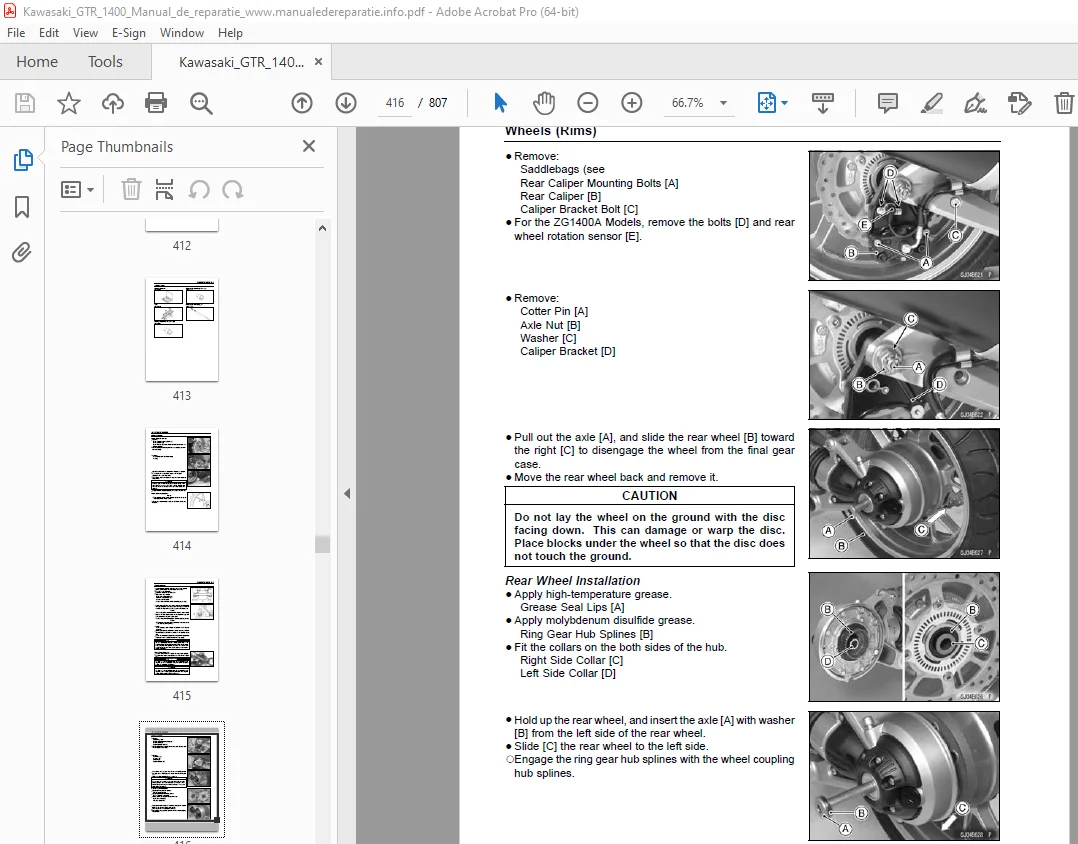
Rear Wheel Removal 415
Rear Wheel Installation 416
Torque – 417
Wheel Coupling Removal 418
Wheel Coupling Installation 418
Wheel Inspection 418
Special Tools – 418
Axle Inspection 419
Coupling Damper Inspection 419
Balance Inspection 419
Balance Adjustment 419
Balance Weight Removal 420
Balance Weight Installation 420
Air Pressure Inspection/Adjustment 422
Tire Inspection 422
Tire Removal 422
Tire Installation 423
Torque – 424
Tire Repair 426
Hub Bearing Removal 427
Special Tools – 427
Hub Bearing Installation 427
Special Tool – 427
Special Tool – 427
Hub Bearing Inspection 427
Hub Bearing Lubrication 428
Final Drive 429
Bearing Puller: 435
Oil Level Inspection 437
Oil Change 437
Final Gear Case Removal 437
Final Gear Case Installation 438
Torque – 438
Final Gear Case Disassembly 439
Special Tool – 439
Special Tool – 439
Special Tool – 441
Special Tool – 441
Final Gear Case 442
Final Gear Case Assembly 442
Special Tool – 442
Special Tool – 443
Torque – 443
Torque – 443
Torque – 444
Special Tools – 444
Torque – 444
Torque – 444
Torque – 445
Sliding Joint Inspection 445
Bevel Gear Inspection 445
Final Bevel Gear Adjustment 445
Backlash Adjustment 446
Torque – 446
Special Tools – 446
Torque – 446
Special Tool – 446
Tooth Contact Adjustment 447
Torque – 447
Special Tool – 447
Correct Tooth Contact Pattern: No adjustment is required 448
Propeller Shaft Removal 449
Propeller Shaft Installation 450
Propeller Shaft Inspection 451
Front Gear Case Removal 452
Front Gear Case Installation 452
Torque – 453
Front Gear Case Disassembly 453
Special Tool – 454
Special Tool – 454
Front Gear Case Assembly 454
Special Tool – 454
Non-permanent Locking Agent – 454
Torque – 454
Torque – 454
Torque – 455
Driven Gear Disassembly 455
Special Tool – 455
Special Tools – 455
Driven Gear Assembly 456
Special Tool – 456
Special Tool – 456
Torque – 456
Damper Cam Removal 456
Special Tool – 456
Damper Cam Installation 457
Torque – 457
Special Tool – 457
Front Bevel Gear Adjustment 457
Front Bevel Gear Adjustment 458
Preload Adjustment 458
Torque – 458
Preload Measurement with Spring Scale 459
Special Tool – 459
Bearing Preloading Mechanism 460
Backlash Adjustment 460
Torque – 460
Torque – 460
Tooth Contact Adjustment 461
Correct Tooth Contact Pattern: No adjustment is required 462
Bevel Gear Inspection 462
Cam Damper Inspection 463
Ball or Needle Bearing Replacement 464
Special Tools – 464
Special Tool – 464
Special Tool – 464
Ball Bearing Wear 464
Tapered Roller Bearing Inspection 465
Needle Bearing Inspection 465
Oil Seal Inspection 465
Brakes 467
Dummy Page 469
ZG1400A Models 470
ZG1400B Models 474
Inside Circlip Pliers: 479
Brake Lever Position Adjustment 480
Brake Pedal Position Inspection 480
Brake Pedal Position Adjustment 480
Torque – 480
Brake Pedal Removal 480
Brake Pedal Installation 481
Torque – 481
Torque – 481
Torque – 481
Front Caliper Removal 482
Rear Caliper Removal 482
Caliper Installation 483
Torque – 483
Front Caliper Disassembly 483
Front Caliper Assembly 483
Rear Caliper Disassembly 483
Rear Caliper Assembly 483
Caliper Fluid Seal Damage 484
Caliper Dust Seal Damage 484
Caliper Piston and Cylinder Damage 485
Front Brake Pad Removal 486
Front Brake Pad Installation 486
Torque – 486
Rear Brake Pad Removal 487
Rear Brake Pad Installation 487
Torque – 487
Brake Pad Wear Inspection 487
Front Master Cylinder Removal 488
Torque – 488
Front Master Cylinder Installation 488
Torque – 488
Torque – 488
Rear Master Cylinder Removal 489
Rear Master Cylinder Installation 489
Torque – 489
Front Master Cylinder Disassembly 489
Rear Master Cylinder Disassembly 489
Master Cylinder Assembly 489
Master Cylinder Inspection (Visual Inspection) 489
Brake Disc Removal 491
Brake Disc Installation 491
Torque – 491
Brake Disc Wear 491
Brake Disc Warp 491
Special Tools – 491
Brake Fluid Level Inspection 492
Brake Fluid Change 492
Brake Line Bleeding 492
Torque – 493
Torque – 494
Torque – 494
Brake Hose and Pipe Removal/Installation 496
Brake Hose and Pipe Inspection 496
Parts Location 497
ABS System Wiring Diagram 498
Terminal Names 499
ABS Servicing Precautions 500
ABS Troubleshooting Outline 502
Special Tool – 502
Special Tool – 503
ABS Diagnosis Flow Chart 504
Inquiries to Rider 505
Pre-Diagnosis Inspection 1 506
Pre-Diagnosis Inspection 2 507
Self-diagnosis Outline 507
Self-diagnosis Procedures 507
Service Code Clearing Procedures 508
Self-diagnosis Flow Chart 509
How to Read Service Codes 510
How to Erase Service Codes 510
ABS Indicator Light (LED) Inspection 512
ABS Indicator Light (LED) is Unlit (When the Key Knob turned to 512
Special Tool – 512
ABS Indicator Light (LED) Lights (When the Motorcycle is Running 513
Special Tool – 513
Solenoid Valve Inspection (Service Code 13,14,17,18) 513
ABS Solenoid Valve Relay Inspection (Service Code 19) 513
Special Tool – 514
Front, Rear Wheel Rotation Difference Abnormal (Service Code 25) 515
ABS Pump Motor Relay Inspection (Service Code 35) 515
Special Tool – 516
Front Wheel Rotation Sensor Signal Abnormal (Service Code 42) 516
Front Wheel Rotation Sensor Wiring Inspection (Service Code 43) 517
Rear Wheel Rotation Sensor Signal Abnormal (Service Code 44) 518
Rear Wheel Rotation Sensor Wiring Inspection (Service Code 45) 519
Power Supply Voltage Abnormal (Under-Voltage) (Service Code 52) 519
Special Tool – 520
Power Supply Voltage Abnormal (Over-Voltage) (Service Code 53) 520
Special Tool – 521
ECU Inspection (Service Code 55) 521
ABS Hydraulic Unit Removal 521
ABS Hydraulic Unit Installation 523
Torque – 523
ABS Hydraulic Unit Inspection 524
Front Wheel Rotation Sensor Removal 524
Front Wheel Rotation Sensor Installation 524
Rear Wheel Rotation Sensor Removal 525
Rear Wheel Rotation Sensor Installation 525
Wheel Rotation Sensor Inspection 526
Wheel Rotation Sensor Air Gap Inspection 526
Wheel Rotation Sensor Rotor Inspection 526
ABS Solenoid Valve Relay Fuse (20 A) Removal 527
ABS Motor Relay Fuse (30 A) Removal 527
ABS ECU Fuse (10 A) Removal 527
Fuse Installation 527
Fuse Inspection 527
Suspension 529
Inside Circlip Pliers: 535
Rebound Damping Force Adjustment 537
Spring Preload Adjustment 537
Front Fork Removal (Each Fork Leg) 538
Front Fork Installation 538
Torque – 538
Torque – 538
Front Fork Oil Change 539
Special Tools – 539
Special Tool – 540
Special Tool – 541
Special Tool – 541
Special Tool – 541
Special Tools – 542
Torque – 543
Front Fork Disassembly 543
Special Tool – 543
Front Fork Assembly 544
Special Tool – 544
Torque – 544
Special Tool – 544
Inner Tube Inspection 545
Dust Seal Inspection 545
Spring Tension 545
Rebound Damping Force Adjustment 546
Spring Preload Adjustment 546
Rear Shock Absorber Removal 546
Rear Shock Absorber Installation 547
Torque – 547
Rear Shock Absorber Inspection 548
Rear Shock Absorber Scrapping 548
Swingarm Removal 549
Special Tool – 549
Swingarm Installation 550
Torque – 550
Special Tool – 550
Torque – 550
Torque – 551
Swingarm Bearing Removal 551
Special Tool – 551
Special Tool – 551
Swingarm Bearing Installation 551
Special Tools – 551
Swingarm Bearing, Sleeve Inspection 552
Torque Rod Removal 553
Torque Rod Installation 553
Torque – 554
Torque Rod Bearing Removal 554
Special Tool – 554
Special Tool – 554
Torque Rod Bearing Installation 554
Tie-Rod Removal 556
Tie-Rod Installation 556
Torque – 556
Rocker Arm Removal 556
Rocker Arm Installation 556
Torque – 556
Tie-Rod and Rocker Arm Bearing Removal 557
Special Tools – 557
Tie-Rod and Rocker Arm Bearing Installation 557
Special Tools – 558
Rocker Arm/Tie-Rod Bearing, Sleeve Inspection 559
Rocker Arm/Tie-Rod Bearing Lubrication 559
Steering 561
Head Pipe Outer Race Press Shaft: 564
Steering Inspection 565
Steering Adjustment 565
Stem, Stem Bearing Removal 566
Special Tool – 567
Special Tool – 567
Stem, Stem Bearing Installation 567
Special Tools – 567
Special Tools – 568
Special Tool – 568
Torque – 568
Torque – 569
Steering Stem Bearing Lubrication 569
Steering Stem Warp 570
Stem Cap Deterioration, Damage 570
Handlebar Removal 571
Handlebar Installation 571
Torque – 571
Torque – 571
Torque – 571
Handlebar Holder Removal 572
Handlebar Holder Installation 572
Torque – 572
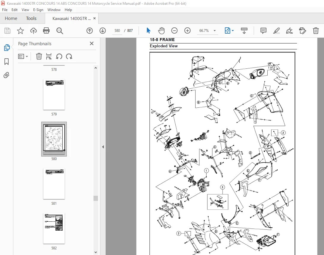
Frame 573
Seat Removal 582
Seat Installation 582
Lower Fairing Removal 583
Lower Fairing Installation 583
Fairing Cover Removal 583
Middle Fairing Removal 584
Middle Fairing Installation 585
Windshield Removal 585
Windshield Installation 586
Upper Fairing Removal 586
Upper Fairing Installation 587
Upper Fairing Disassembly 588
Upper Fairing Assembly 588
Inner Cover Removal 588
Inner Cover Installation 588
Upper Inner Fairing Removal 588
Upper Inner Fairing Installation 589
Lower Inner Fairing Removal 589
Lower Inner Fairing Installation 589
Middle Inner Fairing Removal 589
Middle Inner Fairing Installation 589
Fairing Stay Removal 590
Fairing Stay Installation 591
Upper Fairing Bracket Removal 591
Upper Fairing Bracket Installation 591
Torque – 591
Seat Cover Removal 592
Seat Cover Installation 592
Tail Cover Removal 593
Tail Cover Installation 593
Front Fender Removal 594
Front Fender Installation 594
Flap and Rear Fender Removal 594
Flap and Rear Fender Installation 596
Storage Compartment Removal 597
Storage Compartment Installation 598
Rear Frame Removal 599
Rear Frame Installation 599
Torque – 599
Subframe Removal 599
Frame Inspection 600
Meter Cover Removal 601
Meter Cover Installation 601
Center Stand Removal 603
Special Tools – 603
Center Stand Installation 603
Torque – 603
Sidestand Removal 603
Sidestand Installation 604
Torque – 604
Torque – 604
Saddlebag Removal 605
Saddlebag Installation 605
Saddlebag Disassembly 605
Saddlebag assembly 606
Carrier Removal 607
Carrier Installation 607
Torque – 607
Rear View Mirror Removal 608
Rear View Mirror Installation 608
Dummy Page 609
Electrical System 617
Hand Tester: 635
There are a number of important precautions that are musts when 637
Wiring Inspection 638
Special Tool – 638
Battery Removal 639
Battery Installation 640
Battery Activation 641
Precautions 644
1) 644
2) 644
3) 644
4) 644
Interchange 644
Charging Condition Inspection 645
Refreshing Charge 645
Alternator Cover Removal 647
Alternator Cover Installation 647
Sealant – 647
Torque – 647
Stator Coil Removal 647
Stator Coil Installation 648
Torque – 648
Sealant – 648
Torque – 648
Alternator Rotor Removal 648
Special Tools – 648
Special Tool – 648
Alternator Rotor Installation 648
Special Tools – 649
Torque – 649
Alternator Inspection 649
Special Tool – 650
Regulator/Rectifier Inspection 651
Special Tool – 651
Torque – 651
Charging Voltage Inspection 652
Special Tool – 652
Charging System Circuit 653
Crankshaft Sensor Removal 655
Crankshaft Sensor Installation 656
Torque – 656
Sealant – 656
Torque – 656
Crankshaft Sensor Inspection 656
Special Tool – 656
Crankshaft Sensor Peak Voltage Inspection 656
Special Tools – 657
Timing Rotor Removal 657
Special Tool – 657
Timing Rotor Installation 657
Special Tool – 657
Torque – 657
Stick Coil Removal 657
Stick Coil Installation 658
Stick Coil Inspection 659
Stick Coil Primary Peak Voltage 659
Special Tools – 659
Spark Plug Removal 660
Spark Plug Installation 660
Spark Plug Condition Inspection 660
Camshaft Position Sensor Removal 660
Camshaft Position Sensor Installation 662
Torque – 662
Camshaft Position Sensor Inspection 662
Special Tool – 662
Camshaft Position Sensor Peak Voltage Inspection 662
Special Tools – 662
Interlock Operation Inspection 663
IC Igniter Inspection 664
Ignition System Circuit 665
Starter Motor Removal 666
Starter Motor Installation 666
Torque – 666
Torque – 667
Starter Motor Disassembly 667
Starter Motor Assembly 667
Torque – 668
Torque – 668
Brush Inspection 669
Commutator Cleaning and Inspection 669
Armature Inspection 669
Special Tool – 669
Brush Lead Inspection 670
Special Tool – 670
Right-hand End Cover Assembly Inspection 670
Special Tool – 670
Starter Relay Inspection 670
Special Tool – 670
Torque – 670
Electric Starter Circuit 671
This motorcycle adopts the daylight system and has a headlight r 672
Headlight Beam Horizontal Vertical Adjustment 672
Headlight Beam Vertical Adjustment 672
Headlight Bulb Replacement 672
City Light Bulb Replacement 673
Headlight Removal/Installation 674
Torque – 674
Headlight Relay Inspection 674
Special Tool – 674
Tail/Brake Light (LED) Removal 675
Tail/Brake Light (LED) Installation 676
Torque – 676
License Plate Light Bulb Replacement 676
Torque – 677
Headlight/Tail Light Circuit 678
Turn Signal Light Bulb Replacement 679
Turn Signal Relay Inspection 680
Turn Signal Light Circuit 682
Air Switching Valve Operation Test 683
Air Switching Valve Unit Test 683
Special Tool – 683
Air Switching Valve Circuit 684
Fan Motor Inspection 685
Radiator Fan Circuit 685
Oil Control Solenoid Valve Inspection 686
Special Tool – 686
Oil Control Solenoid Valve Circuit 686
Electric Windshield Assembly Removal 687
Electric Windshield Assembly Installation 687
Electric Windshield Assembly Lubrication 688
Electric Windshield Relay Inspection 688
Special Tool – 689
Electric Windshield Inspection 689
Electric Windshield Circuit 690
Meter Unit Removal 691
Meter Installation 691
Meter Unit Disassembly 692
Meter Operation Inspection 692
Meter Unit Inspection 696
Special Tool – 697
Special Tool – 701
Meter Unit Circuit 710
This motorcycle is equipped with the KIPASS (Kawasaki’s Intell 711
FOB Key Operational Cautions 711
Key Registration 711
KIPASS ECU Power Supply Inspection 711
Special Tools – 711
Steering Lock Unit Replacement 712
KIPASS ECU Replacement 713
KIPASS Signal Relay Inspection 713
KIPASS Signal Diode Inspection 713
Special Tool – 714
KIPASS Circuit 715
Brake Light Timing Inspection 716
Brake Light Timing Adjustment 716
Switch Inspection 716
Special Tool – 716
Rear Brake Light Switch Connections 716
Sidestand Switch Connections 716
Oil Pressure Switch Connections * 716
Water Temperature Sensor Inspection 717
Speed Sensor Removal 717
Speed Sensor Installation 717
Torque – 717
Speed Sensor Inspection 718
Special Tool – 718
Fuel Level Sensor Inspection 718
Special Tool – 718
Torque – 719
Fuel Reserve Switch Inspection 719
Special Tool – 719
Gear Position Switch Removal 720
Gear Position Switch Installation 721
Torque – 721
Gear Position Switch Inspection 721
Special Tool – 721
Oxygen Sensor Removal (Equipped Models) 722
Oxygen Sensor Installation (Equipped Models) 722
Torque – 722
Oxygen Sensor Inspection (Equipped Models) 722
Oxygen Sensor Heater Inspection (Equipped Models) 722
Relay Box Removal 723
Relay Circuit Inspection 723
Diode Circuit Inspection 724
Relay Box Internal Circuit 724
Accessory Relay Inspection 724
30 A Main Fuse Removal 725
Fuse Box Fuse Removal 725
Fuse Installation 726
Fuse Inspection 726
Appendix 727
California Model 762
ABS Equipped Models 768
Non ABS Equipped Models 770
ABS Equipped Models 782
ABS Equipped Models 784
ABS Equipped Models 788
ABS Equipped Models 790
ABS Equipped Models 792
ABS Equipped Models 794
ABS Equipped Models 796
ABS Equipped Models 798
California Model 800
NOTE 802
Engine Doesn’t Start, Starting Difficulty: 802
Starter motor not rotating: 802
Starter motor rotating but engine doesn’t turn over: 802
Engine won’t turn over: 802
No fuel flow: 802
No spark; spark weak: 802
Fuel/air mixture incorrect: 802
Compression Low: 802
Poor Running at Low Speed: 802
Spark weak: 802
Fuel/air mixture incorrect: 802
Compression low: 802
Run-on (dieseling): 803
Other: 803
Poor Running or No Power at High Speed: 803
Firing incorrect: 803
Fuel/air mixture incorrect: 803
Compression low: 803
Knocking: 803
Miscellaneous: 803
Overheating: 803
Firing incorrect: 803
Muffler overheating: 803
Fuel/air mixture incorrect: 803
Compression high: 804
Engine load faulty: 804
Lubrication inadequate: 804
Oil cooler incorrect: 804
Gauge incorrect: 804
Coolant incorrect: 804
Cooling system component incorrect: 804
Over Cooling: 804
Gauge incorrect: 804
Cooling system component incorrect: 804
Clutch Operation Faulty: 804
Clutch slipping: 804
Clutch not disengaging properly: 804
Gear Shifting Faulty: 804
Doesn’t go into gear; shift pedal doesn’t return: 804
Jumps out of gear: 804
Overshifts: 804
Abnormal Engine Noise: 804
Knocking: 804
Piston slap: 804
Valve noise: 804
Other noise: 804
Abnormal Drive Train Noise: 805
Clutch noise: 805
Transmission noise: 805
Drive line noise: 805
Abnormal Frame Noise: 805
Front fork noise: 805
Rear shock absorber noise: 805
Disc brake noise: 805
Other noise: 805
Oil Pressure Warning Light Goes On: 805
Exhaust Smokes Excessively: 805
White smoke: 805
Black smoke: 805
Brown smoke: 805
Handling and/or Stability Unsatisfactory: 805
Handlebar hard to turn: 805
Handlebar shakes or excessively vibrates: 805
Handlebar pulls to one side: 805
Shock absorption unsatisfactory: 806
Brake Doesn’t Hold: 806
Battery Trouble: 806
Battery discharged: 806
Battery overcharged: 806
DESCRIPTION:
Kawasaki 1400GTR CONCOURS 14 ABS CONCOURS 14 Motorcycle Service Manual – PDF DOWNLOAD
Foreword:
- This manual is designed primarily for use by trained mechanics in a properly equipped shop. However, it contains enough detail and basic information to make it useful to the owner who desires to perform his own basic maintenance and repair work. A basic knowledge of mechanics, the proper use of tools, and workshop procedures must be understood in order to carry out maintenance and repair satisfactorily. Whenever the owner has insufficient experience or doubts his ability to do the work, all adjustments, maintenance, and repair should be carried out only by qualified mechanics.
- In order to perform the work efficiently and to avoid costly mistakes, read the text, thoroughly familiarize yourself with the procedures before starting work, and then do the work carefully in a clean area. Whenever special tools or equipment are specified, do not use makeshift tools or equipment. Precision measurements can only be made if the proper instruments are used, and the use of substitute tools may adversely affect safe operation.
For the duration of the warranty period, we recommend that all repairs and scheduled maintenance be performed in accordance with this servicemanual. Any owner maintenance or repair procedure not performed in accordance with this manual may void the warranty.
To get the longest life out of your vehicle.
S.V 16/03/2025