Kawasaki 70TMV-2 WHEEL LOADER SHOP MANUAL 93208-00610 – PDF DOWNLOAD
$29.95
Kawasaki 70TMV-2 WHEEL LOADER SHOP MANUAL 93208-00610 – PDF DOWNLOAD
General Information
Disassembly & Reassembly
Service Standard
Powered by CUMMINS QSB6.7 ENGINE
Serial No. 70C5-4001~
Description
Kawasaki 70TMV-2 WHEEL LOADER SHOP MANUAL 93208-00610 – PDF DOWNLOAD
FILE DETAILS:
Kawasaki 70TMV-2 WHEEL LOADER SHOP MANUAL 93208-00610 – PDF DOWNLOAD
Language :English
Pages :328
Downloadable : Yes
File Type : PDF
IMAGES PREVIEW OF THE MANUAL:
DESCRIPRION:
Kawasaki 70TMV-2 WHEEL LOADER SHOP MANUAL 93208-00610 – PDF DOWNLOAD
General Information
Disassembly & Reassembly
Service Standard
Powered by CUMMINS QSB6.7 ENGINE
Serial No. 70C5-4001~
Foreword
- To ensure good machine performance, reduce failures or problems, and prolong the service life of each component,
- it is necessary to operate the machine as is directed in the Operator and Maintenance Manual.
- To effectively diagnose and repair the machine, it is important to follow the guidelines laid out in this Shop Manual.
Disassembly & Reassembly
Service Standard
- For the engine, refer to the engine Shop Manual provided by the engine manufacturer.
- The purpose of this manual is to provide information on the product and the correct maintenance and repair methods.
Please read this manual to ensure correct troubleshooting and good repair service. - This manual will be periodically reviewed and revised for more satisfactory content. If you have any opinion or
requests, please inform us
Safety precautions
The most important point in providing repair service is safety. To ensure safety, observe the general cautions described below.
– This manual is intended for properly trained and equipped service technicians. – Any work on the machine must be performed by the trained personnel only. – Carefully read this manual to thoroughly understand the operation method before you operate or repair the machine. – Be sure to wear appropriate clothes and protectors, such as safety boots, hard hat and goggles. – Place the machine on level and solid ground, and place chocks against the wheels to prevent movement. – Remove the cable from the battery before starting the service work, and attach a “DO NOT OPERATE!” tag to the steering wheel.IMPORTANT
If a battery terminal is removed from a machine in less than 30 seconds after the key is put into the “OFF” position, it can corrupt the ECM program, which can disable the engine. Always wait 1 full minute to be sure to be past this “write to memory function” prior to removing battery terminals
TABLE OF CONTENTS:
Kawasaki 70TMV-2 WHEEL LOADER SHOP MANUAL 93208-00610 – PDF DOWNLOAD
General Information
Disassembly & Reassembly
Service Standard
Powered by CUMMINS QSB6.7 ENGINE
Serial No. 70C5-4001~
Foreword 2
Safety precautions 3
Safety Symbols 4
CONTENTS 6
00 General Information 12
Symbols 13
Weight of Main Components 14
Bolt Tightening Torque 15
Hose Band Tightening Torque 19
Liquid Gasket and Screw Lock Agent 20
Cautions regarding parts removal 20
Cautions regarding reassembly 20
Screw lock agent application procedure 21
How to wind a seal tape 21
Cautions Regarding Welding Repair Service 22
Cautions Regarding Handling of Bearing 24
Bearing installation cautions 24
Interference fits for a bearing 24
Bearing operation test after installation 25
Bearing removal cautions 25
Applying and Storing Articulation Stopper 26
Applying articulation stopper 26
Storing articulation stopper 26
14 Disassembly & Reassembly Chassis Group 28
Deck 29
Deck removing and installing 29
Deck removing 29
Deck installing 30
Fuel Tank 31
Fuel tank removing and installing 31
Fuel tank removing 31
Fuel tank installing 32
Fuel tank installation cautions 32
Hydraulic Tank 33
Hydraulic tank removing and installing 33
Hydraulic tank removing 33
Hydraulic tank installing 35
Hydraulic tank installation cautions 35
Engine Room 36
Engine room removing and installing 36
Engine room removing 36
Engine room installing 38
Engine room installation cautions 38
Cab 39
Cab removing and installing 39
Cab removing 39
Cab installing 40
Floor Board 41
Floor board removing and installing 41
Floor board removing 41
Floor board installing 43
Floor board installation cautions 43
Boom 44
Boom removing and installing 44
Boom removing 44
Boom installing 45
Boom installation cautions 45
Center Pin 46
Upper center pin 46
Center pin shim adjustment 46
Lower center pin 46
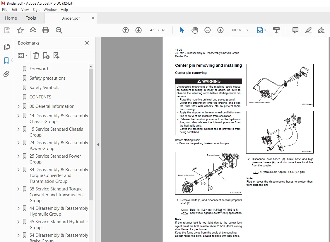
Center pin removing and installing 47
Center pin removing 47
Center pin installing 51
Center pin installation cautions 51
15 Service Standard Chassis Group 52
Linkage 53
Linkage Pin Standard Clearance Values 54
Liner clearance adjustment 55
Center Pin 56
Center pin shim adjustment 56
Grease nipple installing 56
Lower center pin bearing outer ring installing 57
Attachment Leveler 58
Attachment leveler 59
24 Disassembly & Reassembly Power Group 60
Power Line 61
Power line tightening torque 61
Radiator 62
Radiator tightening torque 62
Radiator removing and installing 63
Radiator removing 63
Radiator installing 64
Radiator installation cautions 64
Fan 65
Fan removing and installing 65
Fan removing 65
Fan installing 66
Fan installation cautions 66
Engine 67
Engine removing and installing 67
Engine removing 67
Engine installing 69
Engine installation cautions 69
Propeller Shaft 70
Propeller shaft removing and installing 70
Second propeller shaft removing 70
Third propeller shaft removing 71
Propeller shaft installing 71
Propeller shaft installation cautions 71
Air Cleaner 72
Air cleaner removing and installing 72
Air cleaner removing 72
Air cleaner installing 73
Air cleaner installation cautions 73
Muffler 74
Muffler removing and installing 74
Muffler removing 74
Muffler installing 74
Muffler installation cautions 74
Front Axle Assembly 75
Front axle assembly tightening torque 75
Axle nut tightening procedure 76
Floating seal installation 76
Front axle assembly removing and installing 77
Front axle assembly removing 77
Front axle assembly installing 79
Front axle assembly installation cautions 79
Service brake air bleeding procedure 79
Front axle disassembling and assembling 80
Front axle disassembling 80
Front axle assembling 83
Front axle assembly cautions 84
Floating seal installation 84
Internal gear hub installation 86
Axle nut tightening 86
Brake adjustment 87
Internal Gear Hub 89
Internal gear hub disassembling and assembling 89
Internal gear hub disassembling 89
Internal gear hub assembling 90
Internal gear hub assembly cautions 91
Spider Assembly 92
Spider assy disassembling and assembling 92
Spider assy disassembling 92
Spider assy assembling 93
Spider assy assembly cautions 93
Special Tool 94
Special tool for axle 94
Rear Axle Assembly 99
Rear axle assembly tightening torque 99
Axle nut tightening procedure100
Floating seal installation100
Rear axle assembly removing and installing101
Rear axle assembly removing101
Rear axle assembly installing103
Rear axle disassembling and assembling103
Axle Support104
Axle support tightening torque104
Axle support disassembling and assembling105
Axle support disassembling105
Axle support assembling105
Axle support assembly cautions106
Bushing installation106
Differential Assembly107
Differential assembly removing and installing107
Differential assembly removing107
Differential assembly installing108
Differential assembly installation cautions108
Differential assembly disassembling and assembling109
Front differential tightening torque109
Rear differential tightening torque111
Differential assembly disassembling113
Differential assy assembling117
25 Service Standard Power Group124
Propeller Shaft Service Standard125
Axle and Differential Service Standard126
Axle group126
Differential127
34 Disassembly & Reassembly Torque Converter and Transmission Group128
Torque Converter and Transmission Assembly129
Torque converter and transmission assembly tightening torque129
Torque converter and transmission assembly removing and installing130
Torque converter and transmission assembly removing130
Torque converter and transmission assembly installing134
Transmission assembly installation cautions135
Joint between the torque converter and the engine135
Transmission assembly operation check135
Torque Converter Assembly137
Torque converter assembly bolt tightening torque137
Torque converter assembly disassembling and assembling138
Torque converter assembly disassembling138
Torque converter assembly assembling141
Transmission Assembly145
Transmission assembly bolt tightening torque145
Transmission assembly disassembling and assembling147
Transmission assembly disassembling147
Transmission assembly assembling151
Transmission Forward/Reverse Clutch Pack158
Forward/reverse clutch pack disassembling and assembling158
Forward/reverse clutch pack disassembling158
Forward/reverse clutch pack assembling160
Forward/reverse clutch pack assembly cautions160
Transmission 1st/3rd Speed Clutch Pack161
Transmission 1st/3rd speed clutch pack disassembling and assembling161
Transmission 1st/3rd speed clutch pack disassembling161
Transmission 1st/3rd speed clutch pack assembling162
Transmission 1st/3rd speed clutch pack assembly cautions162
Transmission 2nd Speed Clutch Pack163
Transmission 2nd speed clutch pack disassembling and assembling163
Transmission 2nd speed clutch pack disassembling163
Transmission 2nd speed clutch pack assembling164
Transmission 2nd speed clutch pack assembly cautions164
Transmission 4th Speed Clutch Pack165
Transmission 4th speed clutch pack disassembling and assembling165
Transmission 4th speed clutch pack disassembling165
Transmission 4th speed clutch pack assembling166
Transmission 4th speed clutch pack assembly cautions167
Control Valve Assembly168
Control valve tightening torque168
Control valve removing and installing169
Control valve removing169
Control valve installation cautions170
Control valve disassembling and assembling171
Control valve disassembling171
Control valve assembling172
Control valve assembly cautions172
35 Service Standard Torque Converter and Transmission Group174
Transmission Assembly175
Control Valve176
Gear Pump178
Gear pump specifications178
Clutch Plate Thickness/Piston Stroke179
Clutch plate180
Piston stroke180
Clutch Oil Pressure181
Clutch oil pressure standard value181
44 Disassembly & Reassembly Hydraulic Group182
Hydraulic Parts Removal and Installation Warning183
Hydraulic Parts Disassembly and Assembly Cautions184
Hydraulic parts disassembly cautions184
Hydraulic parts assembly cautions184
Hydraulic Pump Assembly185
Hydraulic pump assembly removing and installing185
Hydraulic pump assembly removing185
Hydraulic pump assembly installing186
Hydraulic pump installation cautions186
Hydraulic pump assembly disassembling and assembling187
Hydraulic pump assembly cross section and tightening torque188
Oil seal replacement procedure189
Hydraulic Cylinder190
Boom cylinder removing and installing190
Boom cylinder removing190
Boom cylinder installing191
Boom cylinder installation cautions191
Bucket cylinder removing and installing192
Bucket cylinder removing192
Bucket cylinder installing193
Bucket cylinder installation cautions194
Steering cylinder removing and installing195
Steering cylinder removing195
Steering cylinder installing196
Steering cylinder installation cautions196
Hydraulic cylinder disassembling and assembling197
Hydraulic cylinder cross section and tightening torque197
Hydraulic cylinder disassembling199
Hydraulic cylinder assembling201
Hydraulic cylinder assembly cautions202
Pilot Valve204
Pilot valve removing and installing204
Pilot valve removing204
Pilot valve installing205
Pilot valve installation cautions205
Pilot valve disassembling and assembling206
Pilot valve cross section and tightening torque206
Pilot valve disassembling (S/N 4001~4150)207
Pilot valve assembling214
Pilot valve assembly cautions214
Pilot valve disassembling (S/N 4151~)218
Pilot valve assembling224
Pilot valve assembly cautions224
Multiple Control Valve225
Multiple control valve removing and installing225
Multiple control valve removing225
Multiple control valve installing226
Multiple control valve installation cautions227
Multiple control valve disassembling and assembling228
Multiple control valve cross section and tightening torque228
Multiple control valve disassembling229
Multiple control valve assembling231
Multiple control valve assembly cautions231
Orbitrol®232
Orbitrol® removing and installing232
Orbitrol® removing232
Orbitrol® installing233
Orbitrol® installation cautions233
Orbitrol® disassembling and assembling234
Orbitrol® cross section and tightening torque234
Orbitrol® disassembling235
Orbitrol® assembling239
Priority Valve244
Priority valve removing and installing244
Priority valve removing244
Priority valve installing245
Priority valve cross section and tightening torque246
Priority valve disassembly cautions247
Fan Motor248
Fan motor removing and installing248
Fan motor removing248
Fan motor installing249
Fan motor installation cautions250
45 Service Standard Hydraulic Group252
Hydraulic Cylinder253
Pilot Valve255
54 Disassembly & Reassembly Brake Group258
Unloader Valve259
Unloader valve removing and installing259
Unloader valve removing259
Unloader valve installing260
Unloader valve disassembling and assembling261
Unloader valve cross section and tightening torque261
Unloader valve disassembling264
Unloader valve assembling264
Manifold Valve Assembly265
Valve assembly removing and installing265
Valve assembly removing265
Valve assembly installing266
Valve assembly installation cautions266
Valve assembly disassembling and assembling266
Accumulator268
Accumulator removing and installing268
Accumulator removing268
Accumulator installing269
Accumulator installation cautions269
Accumulator disassembling and assembling269
Accumulator disassembling269
Accumulator assembling270
Nitrogen gas charging271
Nitrogen gas charging procedure271
Brake Valve273
Brake valve removing and installing273
Brake valve removing273
Brake valve installing274
Brake valve installation cautions274
Brake valve disassembling and assembling275
Brake valve cross section and tightening torque (main valve)275
Brake valve disassembling276
Brake valve assembling279
Brake valve assembly cautions280
Service Brake281
Service brake disassembling and assembling281
Service brake installation cautions281
Parking Brake Actuator282
Parking brake actuator removing and installing282
Parking brake actuator removing282
Parking brake actuator installing283
Parking brake actuator adjusting284
Parking brake actuator adjustment procedure284
Parking brake actuator disassembling and assembling285
Parking brake actuator cross section and tightening torque285
Parking brake actuator disassembling286
Parking brake actuator assembling287
Parking Brake288
Parking brake removing and installing / disassembling and assembling288
Parking brake removing and disassembling288
Parking brake installing and assembling289
55 Service Standard Brake Group290
Brake Valve291
Service Brake293
Parking Brake294
74 Disassembly & Reassembly Operator Station Group296
Air Conditioner (S/N 4001~4100)297
Air conditioner removing and installing297
Air conditioner removing297
Air conditioner installing298
Air conditioner disassembling and assembling299
Air conditioner tightening torque299
Compressor V-belt302
Compressor V-belt adjustment procedure303
Air Conditioner (S/N 4101~)304
Air conditioner removing and installing304
Air conditioner removing304
Air conditioner installing305
Air conditioner disassembling and assembling306
Air conditioner tightening torque306
Air conditioner disassembling309
Air conditioner assembling313
75 Service Standard Operator Station Group314
Air Conditioner315
Air conditioner periodical inspection/servicing315
Air conditioner tightening torque315
Tightening torque for hose and pipes315
Tightening torque for screws and bolts in special control regions315
INDEX316
Maintenance Log321
Notes325
S.M 2/2/25