Trusted Business
Verified & Licensed
Virus Free Files
100% Safe Downloads
Secure Payment
SSL Protected
Instant Delivery
Available Immediately
Kawasaki 70ZV WHEEL LOADER SHOP MANUAL 93208-00133 – PDF DOWNLOAD
$30.95
Kawasaki 70ZV WHEEL LOADER SHOP MANUAL 93208-00133 – PDF DOWNLOAD
General Information
Standard Measurement Values for Performance Check
Function & Structure Check & Adjustment
Standard Measurement Values for Performance Check
Function & Structure Check & Adjustment
Powered by CUMMINS QSB5.9 ENGINE
Serial No. 70C4-9001 and up
Serial No. 70C4-9001 and up
Instant PDF Download
Available immediately
Save to Your Device
Download & keep forever
Antivirus Scanned
100% virus-free
Trusted Worldwide
175,000+ customers
Description
Kawasaki 70ZV WHEEL LOADER SHOP MANUAL 93208-00133 – PDF DOWNLOAD
FILE DETAILS:
Kawasaki 70ZV WHEEL LOADER SHOP MANUAL 93208-00133 – PDF DOWNLOAD
Language :English
Pages :526
Downloadable : Yes
File Type : PDF
IMAGES PREVIEW OF THE MANUAL:
DESCRIPTION:
Kawasaki 70ZV WHEEL LOADER SHOP MANUAL 93208-00133 – PDF DOWNLOAD
General Information
Standard Measurement Values for Performance Check
Function & Structure Check & Adjustment
Standard Measurement Values for Performance Check
Function & Structure Check & Adjustment
Powered by CUMMINS QSB5.9 ENGINE
Serial No. 70C4-9001 and up
Serial No. 70C4-9001 and up
Foreword
-
To ensure good machine performance, reduce failures or problems, and prolong the service life of
each component, it is necessary to operate the machine as is directed in the Operator and
Maintenance Manual. - To effectively diagnose and repair the machine, it is important to follow the guidelines laid out
in this Shop Manual.
General Information
Function and structure
- For the engine, refer to the engine Shop Manual provided by the engine manufacturer.
- The purpose of this manual is to provide information on the product and the correct maintenance and
repair meth- ods. Please read this manual to ensure correct troubleshooting and good repair
service. - This manual will be periodically reviewed and revised for more satisfactory content. If
you have any opinion or requests, please inform us.
TABLE OF CONTENTS:
Kawasaki 70ZV WHEEL LOADER SHOP MANUAL 93208-00133 – PDF DOWNLOAD
General Information
Standard Measurement Values for Performance Check
Function & Structure Check & Adjustment
Standard Measurement Values for Performance Check
Function & Structure Check & Adjustment
Powered by CUMMINS QSB5.9 ENGINE
Serial No. 70C4-9001 and up
Serial No. 70C4-9001 and up
Foreword 2
Safety Symbols 3
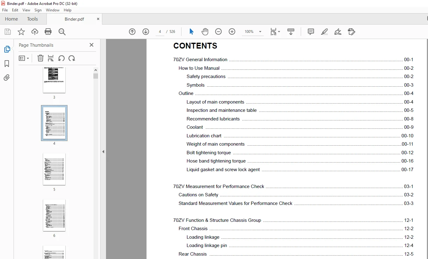
CONTENTS 4
00 General Information 16
How to Use Manual 17
Safety precautions 17
Symbols 18
Outline 19
Layout of main components 19
Inspection and maintenance table 20
Recommended lubricants 23
Coolant 24
Coolant specification 24
Recommended mixture of antifreeze 24
Lubrication chart 25
Weight of main components 26
Bolt tightening torque 27
Hexagon bolt 27
Flanged hexagon bolt 30
Hose band tightening torque 31
Liquid gasket and screw lock agent 32
Cautions regarding parts removal 32
Cautions regarding reassembly 32
Screw lock agent application procedure 33
How to wind a seal tape 33
Cautions regarding welding repair service 34
Cautions 34
03 Measurement for Performance Check 36
Cautions on Safety 37
Standard Measurement Values for Performance Check 38
12 Function & Structure Chassis Group 40
Front Chassis 41
Loading linkage 41
Loading linkage pin 43
Rear Chassis 44
Floor board mount 44
Floor board 44
Viscous mount 44
Fuel tank (S/N 9001~9005) 45
Fuel tank (S/N 9006~) 46
Center Pin 47
Upper center pin 47
Lower center pin 47
Dust seal 48
13 Check & Adjustment Chassis Group 50
Linkage Pin 51
Liner 51
Adjustment 52
Center Pin 53
Adjusting shim 53
Installing bearing cover 53
Installing bearing outer ring 54
22 Function & Structure Power Group 56
Power Line 57
Engine / Transmission 58
Engine / transmission mount 58
Radiator 59
Radiator mount 60
Thermo sensing valve mount (S/N 9011~) 60
Propeller Shaft 61
Second propeller shaft assembly 62
Third propeller shaft assembly 63
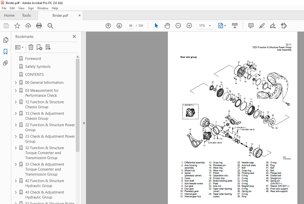
Axle Assembly 65
Axle Support 67
Differential Gear (TPD) (S/N 9001~9017) 71
Torque Proportioning Differential (S/N 9001~9017) 74
Difference in gear shapes 74
Contact between pinion and side gear 74
Operation of T P D 75
Differential Gear (LSD) (S/N 9018~) 76
Limited Slip Differential (S/N 9018~) 78
LSD function 79
LSD operation 79
23 Check & Adjustment Power Group 80
Engine 81
Measuring engine speed 81
Measurement instrument 81
Standard measurement value 81
Measuring engine oil pressure 81
Measurement instrument 81
Install position 81
Standard measurement value 81
Propeller Shaft 82
Propeller shaft phase 82
Second propeller shaft alignment 82
Tightening torque 83
Axle 84
Axle nut tightening procedure 84
Differential gear adjustment procedure 85
Preload adjustment 86
Bearing installation 86
Oil seal installation 86
Adjusting tooth contact 87
32 Function & Structure Torque Converter and Transmission Group 90
Torque Converter 91
Torque converter structure 91
Power flow path 91
Torque multiplication 91
Torque Converter Gear Pump 92
Pump specifications 92
Transmission 93
Clutch combination 93
Shift lever position 93
QUAD (Quick up and down shift) 93
Gear train and number of teeth 94
Clutch specifications 95
Friction plate: mm (in) 95
Valve location 96
Clutch Pack 98
Forward and reverse clutch 98
1st and 2nd speed clutch 99
3rd and 4th speed clutch 100
Power Flow Path in the Transmission 101
Forward 101
Forward 1st speed 101
Forward 2nd speed 102
Forward 3rd speed 103
Forward 4th speed 104
Reverse 105
Reverse 1st speed 105
Reverse 2nd, 3rd, and 4th speeds 105
Hydraulic System Diagram 106
Hydraulic Circuit Diagram 107
Oil Flow 108
Oil flow in the torque converter line 108
From torque converter gear pump to torque converter 108
Return oil from torque converter 108
Return oil from cooler 108
Oil flow to the clutches 108
To forward and reverse clutches 108
To speed clutches 108
T/C and T/M Oil Circulation 109
Control Valve 110
Main control valve 110
3rd, 4th speed control valve 110
Oil port layout 111
Layout of ports on mounting surface of control valve (at T/M case side) 111
Modulation Mechanism 112
Clutch control oil pressure curve 112
Modulation mechanism operation 113
Accumulator 116
Accumulator for 1st and 2nd speed clutch 116
Clutch Solenoid Valve 117
For forward/reverse and speed clutches 117
After power-off (clutch disengaged status) 117
After power-on (clutch engaged status) 118
33 Check & Adjustment Torque Converter and Transmission Group 120
Clutch Oil Pressure 121
Measuring clutch oil pressure 121
42 Function & Structure Hydraulic Group 124
Flushing Hydraulic Circuit 125
Purpose of flushing 125
Cautions on Hydraulic Parts Replacement 126
Hydraulic Circuit Symbols 127
Hydraulic lines 127
Pumps & motors 127
Cylinders 127
Operation methods 128
Pressure control valve 128
Flow control valve 128
Directional control valve 129
Check valve 129
Miscellaneous hydraulic symbols 130
Hydraulic System Operation 131
Hydraulic system operation outline 131
Loading system 131
Steering system 132
Fan motor system 132
Ride control system (OPT) 132
Layout of Hydraulic Units 133
Hydraulic Tank 134
Hydraulic tank breather valve (tank cap) 137
Hydraulic tank specifications 138
Hydraulic oil level check 139
Hydraulic Pump 140
Hydraulic pump specifications 140
Hydraulic pump principle 141
Hydraulic pump wear plate 142
Hydraulic pump bushing lubrication 142
Hydraulic Cylinder 143
Boom cylinder 143
Bucket cylinder 144
Steering cylinder 145
Hydraulic cylinder specifications 146
Loading System 147
Reducing Valve (for Pilot Pressure) 148
Pilot Valve (S/N 9001~9030) 149
Pilot valve operation 151
Pilot valve detent magnet solenoid 153
Detent adjustment procedure 153
Pilot valve (S/N 9031~) 154
Pilot valve operation 156
Pre-detent and detent magnet solenoid 158
Multiple Control Valve (KML28/2T102) 159
Multiple control valve specifications 160
Multiple control valve main relief valve 161
Main relief valve operation 161
Adjusting set pressure 162
Multiple control valve overload relief valve (with make-up function) 163
Overload relief valve operation 163
Make-up valve operation 164
Adjusting set pressure 164
Multiple control valve make-up valve 165
Make-up valve operation 165
Multiple control valve bucket spool 166
Bucket spool operation 166
Multiple control valve boom spool 168
Boom spool operation 168
Adapter (Orifice) 171
Vibration Damper (OPT) 172
Vibration damper hydraulic circuit 172
Vibration damper function 173
Vibration damper operation 173
Preparation mode (the vibration damper switch is OFF) 173
Running mode (the vibration damper switch is ON) 173
Vibration Damper (D/D) Valve Assembly 174
Outline 174
Section drawing 175
Solenoid valve (for vibration damper) 176
Specification 176
Accumulator (for vibration damper) 177
Function 177
Specification 177
Steering System 178
Orbitrol® 179
Orbitrol® structure 179
Valve part 179
Rotor part 180
Orbitrol® specification 180
Orbitrol® operation 181
Neutral 181
Turn 182
Orbitrol® feed-back mechanism operation 183
Steering speed and flow rate control 184
Hydraulic pump oil amount and steering force 184
Orbit rotor operation principle 185
Steering Valve (KVS25-A1 0/A3 0/20) 186
Steering valve operation 188
Neutral position 188
Left turn position 189
Steering plunger variable throttle 190
Steering valve flow control plunger 191
Steering valve main relief valve 192
When the pressure is at the preset value or less 192
When the pressure exceeds the preset value 193
Steering valve overload relief valve 194
Overload relief valve operation 195
Steering pilot circuit and its operation 196
Flow amplifier notch and pilot orifice 197
Stop Valve 198
Stop valve function 199
Stop valve operation 200
Reducing Valve (for Orbitrol®) 201
Steering Line Filter 202
Secondary Steering 203
Secondary steering circuit 203
Secondary steering operation 203
Secondary steering motor and pump 205
Fan Motor System 206
Fan Motor Line (S/N 9001~9010) 207
Fan motor (GM20W-1T7T8-B70A61L) 209
Fan motor specifications 209
Valve assembly (for fan motor) 210
Relief valve (two-step relief) 211
Relief valve operation 212
Solenoid valve (for fan speed control) 214
Fan Motor Line (S/N 9011~) 215
Fan motor (GM20W-1T7T8-K70A61L) 217
Thermo sensing valve 218
Thermo sensing valve specifications 218
Thermo sensing valve operation 219
Fan motor relief valve assembly 220
Fan motor relief valve 221
Fan motor check valve (Make-up valve) 221
Reversing Fan Motor (OPT) 222
Reversing Fan Motor Line (OPT) 224
Reversing fan motor (PI-GM25B-1Q23D) 227
Thermo sensing valve (for reversing fan) 227
Reversing fan motor valve 228
43 Check & Adjustment Hydraulic Group 230
Loading/Steering Circuit Relief Valve 231
Loading circuit relief valve setting pressures 231
Measurement instruments 231
Standard measurement value 231
Gauge port 232
Measuring loading circuit main relief pressure 233
Measuring loading circuit overload relief pressure 233
Adjusting overload relief pressure 234
Measuring pilot circuit pressure 234
Adjusting pilot line pressure 235
Steering circuit relief valve setting pressures 236
Measurement instruments 236
Standard measurement value 236
Gauge port 237
Measuring steering circuit main relief pressure 238
Measuring steering circuit overload relief pressure 239
Measuring pilot circuit relief pressure (Reducing pressure) 240
Hydraulic Cylinder 241
Cylinder natural drift 241
Measurement instrument 241
Standard measurement value (mm/min) (in/min) 241
Measurement procedure 241
Stop Valve 243
Stop valve adjustment procedure 243
Fan Revolution (S/N 9001~9010) 244
Fan maximum revolution measurement 244
Fan revolution adjustment 245
High revolution (high pressure) adjustment 245
Low revolution (low pressure) adjustment 245
Fan Revolution (S/N 9011~) 246
Fan maximum revolution measurement 246
Fan revolution adjustment 247
52 Function & Structure Brake Group 248
Brake System Outline 249
Service brake 249
Parking brake 249
Adjustment of axle internal pressure 249
Brake Units Layout 250
Unloader Valve 251
Unloader valve operation 252
Valve Unit 253
Brake Accumulator Line 254
Accumulator 255
Reducing valve (for accumulator circuit) 256
In-Line Filter 257
Brake Valve 258
Brake main valve (left pedal) 258
Brake pilot valve (right pedal) 259
Brake valve performance chart 260
Brake valve outline 261
Main valve (tandem type) operation 261
Pilot valve operation 262
Stop lamp pressure switch 263
Pressure switch (for Declutch) 264
Service Brake 265
Service brake operation 265
Service brake friction plate 266
Brake circuit air bleeding procedure 267
Bleeding air from the brake valves 268
Bleeding air from brake pipes and axle housing hubs 268
Parking Brake 269
Parking brake operation 270
Parking brake solenoid valve 271
Solenoid valve operation 271
Solenoid valve specifications 271
Parking Brake Manual Release 272
Parking Brake Spring Chamber 274
Brake Circuit Check Valve 275
53 Check & Adjustment Brake Group 276
Brake Circuit Oil Pressure 277
Unloader valve setting pressure 277
Measurement procedure 278
Accumulator circuit pressure measurement and adjusting 279
Measuring reducing valve setting pressure 279
Measurement procedure 279
Adjusting reducing valve setting pressure 280
Brake valve oil pressure 281
Measurement procedure 281
Brake valve performance 282
Service Brake 283
Service brake performance check 283
Service brake friction plate wear measurement 284
Measurement procedure 285
Cautions on installing brake discs 285
Parking Brake 286
Parking brake performance check 286
Parking brake clearance adjustment 288
Adjustment procedure 288
Brake lining abrasion check 289
62 Function & Structure Electrical Group 290
How to Use Electrical Wiring Diagram 291
Utilisation des schémas des câblages électriques (FRANÇAIS) 292
Verwendung des elektrischen Schaltplans (DEUTSCH) 293
Modalità di utilizzo dello schema dei collegamenti elettrici (ITALIANO) 294
Cómo utilizar un Diagrama de Alambrado Eléctrico (ESPAÑOL) 295
Como Utilizar o Diagrama de Ligações Eléctricas (PORTUGUÊS) 296
Electrical Cable Color Codes 297
Electrical Circuit Symbols 298
Sensor Mount 299
Fuse 300
Fuse box location 300
Fuse box 301
Fusible link 302
Engine Start Circuit 304
Engine start circuit diagram 304
Neutral starter 304
Shift lever neutral (N) position 304
Shift lever forward/reverse (F/R) position 304
Starter switch 305
Battery relay 306
Battery relay operation 306
Alternator I(R) terminal wire 306
Diode unit 307
Neutral relay 307
Magnet switch 308
Voltage relay 308
Power Generating/Charging Circuit 309
Alternator 309
ECM (Engine Controller) 310
Function of ECM 310
Connection diagram 310
Monitor lamp test 311
Failure diagnosis 312
Diag Inc/Dec switch assembly (option) 312
Engine diagnostic switch (option) 314
Failure diagnostic chart 315
Increment decrement switch (option) 316
Quantum fault code information 318
Accelerator pedal 325
Accelerator pedal installation 326
Accelerator pedal 327
Accelerator pedal installation 328
Transmission Control Circuit and Monitor Circuit 329
Controller 329
LED inspection windows 330
Controller connection diagram 332
Controller function 333
Forward/reverse (F/R) shifting and speed change 333
Automatic shift 335
Machine speed sensor 336
QUAD (downshift) switch operation 337
Switching from automatic to manual 338
Transmission cut off (Declutch) 339
Pressure switch for inching (declutch) 340
Back-up alarm 341
Parking brake 342
Transmission controller failure warning 344
Secondary steering function 345
Monitoring system 346
Items to be monitored and operation condition 346
Operation monitor lamps 347
Instrument Panel and Switch 348
Instrument panel 348
Instrument panel rear surface 349
Gauge circuit 350
Temperature sensor 350
Fuel level sensor 351
Electrical Detent Circuit 352
Bucket leveler 352
Boom kick-out 353
Float 353
Proximity switch 353
Detent solenoid 354
Diode 355
Diode check method 356
Caution for diode check method 356
Continuity check mode 356
Diode check mode 356
Resistance check mode 357
Surge voltage and surge suppression diodes 358
Diagnostic System 359
Diagnostic system flow 359
Diagnostic failure history memory data 360
Warning monitor/control 360
Failure code 361
Malfunction mode symbol 362
Diagnostic (T/M controller) failure code detection condition 363
Diagnostic failure history indication and deletion 364
Failure history indication 364
Failure history deletion 364
Diagnostic switch 366
63 Check & Adjustment Electrical Group 368
Cautions Regarding Electric Circuit Check 369
Disconnecting or reinstalling connector 369
How to attach the probes of the circuit tester 371
Electrical Transmission Control System Troubleshooting Flowchart 372
Standard troubleshooting flowchart 372
Transmission Controller Abnormal Operation Judgment 373
Transmission controller check 373
When the “controller failure” monitor lamp lights: 373
When the output units (solenoid valve, etc ) do not operate properly: 373
If the input units or circuit are not defective 374
Transmission controller LED indicator 375
Electrical Circuit Check 377
Shift lever input electrical circuit check 377
Inching (Declutch) input electrical circuit check 379
QUAD switch input electrical circuit check 381
Machine speed sensor input electrical circuit check 382
Clutch solenoid valve output electrical circuit check 383
Neutral relay electrical circuit check 386
Parking brake electrical circuit check 387
Gauge circuit electrical circuit check 389
Bucket positioner electrical circuit check 391
72 Function & Structure Operator Station Group 394
Cabin 395
Glass 396
1 Part number 32011-21690 397
2 Part number 32011-21700 397
3 Part number 32011-21500 398
Wiper mount 399
Front wiper 399
Rear wiper 399
Wiper motor 400
Operator Seat 402
Steering and Transmission Shift Lever 403
Tilt case 404
Column shaft 405
Shift lever 405
Air Conditioner 406
Air conditioner components 406
Air conditioner specifications (system performance) 406
Air conditioner structure 407
Cooling unit 407
Heater and accessories 409
Air distributor (hood & defroster selection box) 409
Air compressor (with magnetic clutch) 410
Condenser unit 410
Control unit 411
Cooling mechanism 412
Principle of cooling 412
Refrigerant 413
Refrigerant characteristics 414
Cooling circuit 415
Electrical circuit 416
Control schematic drawing 416
Air conditioner functions of components 417
Control panel 417
Air conditioner unit 424
Compressor and magnetic clutch 433
Condenser unit 436
Receiver dryer 438
Sight glass 440
Pressure switches 440
Pressure relief valve 442
Relay A 443
Relay B 443
Refrigerant hose 444
Charge of refrigerant 445
Work procedure 446
Refrigerant charging tools 448
Refrigerant charging procedure 452
Troubleshooting using the gauge manifold 458
Air conditioner troubleshooting 463
Fault diagnosis procedure 463
73 Check & Adjustment Operator Station Group 472
Air Conditioner 473
Adjustment of lubricating oil quantity when components of air conditioner are replaced 473
When the compressor is replaced 474
When the evaporator is replaced 475
When the condenser is replaced 475
Adjustment of air gap (between hub and rotor) in compressor magnetic clutch 476
Compressor V-belt adjustment 477
Belt adjustment procedure 477
Adjustment value 477
Parts to be replaced periodically 478
Air filters 478
Receiver dryer 478
INDEX 480
Maintenance Log 485
Notes 489
92 Cross-section drawing & Diagrams 493
Axle Assembly 494
Torque Converter and Transmission 495
Loading/Steering Hydraulic Line (S/N 9001~9010) 496
Loading/Steering Hydraulic Line (S/N 9011~) 497
Brake Circuit (S/N 9001~9010) 498
Brake Circuit (S/N 9011~) 499
Electrical Wiring Diagram (1/2) (S/N 9001~9010) 500
Electrical Wiring Diagram (2/2) (S/N 9001~9010) 501
Electrical Wiring Diagram (1/2) (S/N 9011~9017) 502
Electrical Wiring Diagram (2/2) (S/N 9011~9017) 503
Electrical Wiring Diagram (1/2) (S/N 9018~9030) 504
Electrical Wiring Diagram (2/2) (S/N 9018~9030) 505
Electrical Wiring Diagram (1/2) (S/N 9031~) 506
Electrical Wiring Diagram (2/2) (S/N 9031~) 507
Electrical wiring diagram abbreviation chart 508
Electrical Wiring Diagram (CAB) 509
Electrical Connection Diagram (S/N 9001~9010) 512
Electrical Connection Diagram (S/N 9011~) 513
Electrical Wiring (Reversal Fan) (OPT) 514
Electrical Equipment Layout 515
Electrical Circuit Diagram (Cabin Air Conditioner) 524
Electrical Wiring Diagram (Cabin Air Conditioner) 525
Equipment Operation Table (Cabin Air Conditioner) 526
Safety Symbols 3
CONTENTS 4
00 General Information 16
How to Use Manual 17
Safety precautions 17
Symbols 18
Outline 19
Layout of main components 19
Inspection and maintenance table 20
Recommended lubricants 23
Coolant 24
Coolant specification 24
Recommended mixture of antifreeze 24
Lubrication chart 25
Weight of main components 26
Bolt tightening torque 27
Hexagon bolt 27
Flanged hexagon bolt 30
Hose band tightening torque 31
Liquid gasket and screw lock agent 32
Cautions regarding parts removal 32
Cautions regarding reassembly 32
Screw lock agent application procedure 33
How to wind a seal tape 33
Cautions regarding welding repair service 34
Cautions 34
03 Measurement for Performance Check 36
Cautions on Safety 37
Standard Measurement Values for Performance Check 38
12 Function & Structure Chassis Group 40
Front Chassis 41
Loading linkage 41
Loading linkage pin 43
Rear Chassis 44
Floor board mount 44
Floor board 44
Viscous mount 44
Fuel tank (S/N 9001~9005) 45
Fuel tank (S/N 9006~) 46
Center Pin 47
Upper center pin 47
Lower center pin 47
Dust seal 48
13 Check & Adjustment Chassis Group 50
Linkage Pin 51
Liner 51
Adjustment 52
Center Pin 53
Adjusting shim 53
Installing bearing cover 53
Installing bearing outer ring 54
22 Function & Structure Power Group 56
Power Line 57
Engine / Transmission 58
Engine / transmission mount 58
Radiator 59
Radiator mount 60
Thermo sensing valve mount (S/N 9011~) 60
Propeller Shaft 61
Second propeller shaft assembly 62
Third propeller shaft assembly 63
Axle Assembly 65
Axle Support 67
Differential Gear (TPD) (S/N 9001~9017) 71
Torque Proportioning Differential (S/N 9001~9017) 74
Difference in gear shapes 74
Contact between pinion and side gear 74
Operation of T P D 75
Differential Gear (LSD) (S/N 9018~) 76
Limited Slip Differential (S/N 9018~) 78
LSD function 79
LSD operation 79
23 Check & Adjustment Power Group 80
Engine 81
Measuring engine speed 81
Measurement instrument 81
Standard measurement value 81
Measuring engine oil pressure 81
Measurement instrument 81
Install position 81
Standard measurement value 81
Propeller Shaft 82
Propeller shaft phase 82
Second propeller shaft alignment 82
Tightening torque 83
Axle 84
Axle nut tightening procedure 84
Differential gear adjustment procedure 85
Preload adjustment 86
Bearing installation 86
Oil seal installation 86
Adjusting tooth contact 87
32 Function & Structure Torque Converter and Transmission Group 90
Torque Converter 91
Torque converter structure 91
Power flow path 91
Torque multiplication 91
Torque Converter Gear Pump 92
Pump specifications 92
Transmission 93
Clutch combination 93
Shift lever position 93
QUAD (Quick up and down shift) 93
Gear train and number of teeth 94
Clutch specifications 95
Friction plate: mm (in) 95
Valve location 96
Clutch Pack 98
Forward and reverse clutch 98
1st and 2nd speed clutch 99
3rd and 4th speed clutch 100
Power Flow Path in the Transmission 101
Forward 101
Forward 1st speed 101
Forward 2nd speed 102
Forward 3rd speed 103
Forward 4th speed 104
Reverse 105
Reverse 1st speed 105
Reverse 2nd, 3rd, and 4th speeds 105
Hydraulic System Diagram 106
Hydraulic Circuit Diagram 107
Oil Flow 108
Oil flow in the torque converter line 108
From torque converter gear pump to torque converter 108
Return oil from torque converter 108
Return oil from cooler 108
Oil flow to the clutches 108
To forward and reverse clutches 108
To speed clutches 108
T/C and T/M Oil Circulation 109
Control Valve 110
Main control valve 110
3rd, 4th speed control valve 110
Oil port layout 111
Layout of ports on mounting surface of control valve (at T/M case side) 111
Modulation Mechanism 112
Clutch control oil pressure curve 112
Modulation mechanism operation 113
Accumulator 116
Accumulator for 1st and 2nd speed clutch 116
Clutch Solenoid Valve 117
For forward/reverse and speed clutches 117
After power-off (clutch disengaged status) 117
After power-on (clutch engaged status) 118
33 Check & Adjustment Torque Converter and Transmission Group 120
Clutch Oil Pressure 121
Measuring clutch oil pressure 121
42 Function & Structure Hydraulic Group 124
Flushing Hydraulic Circuit 125
Purpose of flushing 125
Cautions on Hydraulic Parts Replacement 126
Hydraulic Circuit Symbols 127
Hydraulic lines 127
Pumps & motors 127
Cylinders 127
Operation methods 128
Pressure control valve 128
Flow control valve 128
Directional control valve 129
Check valve 129
Miscellaneous hydraulic symbols 130
Hydraulic System Operation 131
Hydraulic system operation outline 131
Loading system 131
Steering system 132
Fan motor system 132
Ride control system (OPT) 132
Layout of Hydraulic Units 133
Hydraulic Tank 134
Hydraulic tank breather valve (tank cap) 137
Hydraulic tank specifications 138
Hydraulic oil level check 139
Hydraulic Pump 140
Hydraulic pump specifications 140
Hydraulic pump principle 141
Hydraulic pump wear plate 142
Hydraulic pump bushing lubrication 142
Hydraulic Cylinder 143
Boom cylinder 143
Bucket cylinder 144
Steering cylinder 145
Hydraulic cylinder specifications 146
Loading System 147
Reducing Valve (for Pilot Pressure) 148
Pilot Valve (S/N 9001~9030) 149
Pilot valve operation 151
Pilot valve detent magnet solenoid 153
Detent adjustment procedure 153
Pilot valve (S/N 9031~) 154
Pilot valve operation 156
Pre-detent and detent magnet solenoid 158
Multiple Control Valve (KML28/2T102) 159
Multiple control valve specifications 160
Multiple control valve main relief valve 161
Main relief valve operation 161
Adjusting set pressure 162
Multiple control valve overload relief valve (with make-up function) 163
Overload relief valve operation 163
Make-up valve operation 164
Adjusting set pressure 164
Multiple control valve make-up valve 165
Make-up valve operation 165
Multiple control valve bucket spool 166
Bucket spool operation 166
Multiple control valve boom spool 168
Boom spool operation 168
Adapter (Orifice) 171
Vibration Damper (OPT) 172
Vibration damper hydraulic circuit 172
Vibration damper function 173
Vibration damper operation 173
Preparation mode (the vibration damper switch is OFF) 173
Running mode (the vibration damper switch is ON) 173
Vibration Damper (D/D) Valve Assembly 174
Outline 174
Section drawing 175
Solenoid valve (for vibration damper) 176
Specification 176
Accumulator (for vibration damper) 177
Function 177
Specification 177
Steering System 178
Orbitrol® 179
Orbitrol® structure 179
Valve part 179
Rotor part 180
Orbitrol® specification 180
Orbitrol® operation 181
Neutral 181
Turn 182
Orbitrol® feed-back mechanism operation 183
Steering speed and flow rate control 184
Hydraulic pump oil amount and steering force 184
Orbit rotor operation principle 185
Steering Valve (KVS25-A1 0/A3 0/20) 186
Steering valve operation 188
Neutral position 188
Left turn position 189
Steering plunger variable throttle 190
Steering valve flow control plunger 191
Steering valve main relief valve 192
When the pressure is at the preset value or less 192
When the pressure exceeds the preset value 193
Steering valve overload relief valve 194
Overload relief valve operation 195
Steering pilot circuit and its operation 196
Flow amplifier notch and pilot orifice 197
Stop Valve 198
Stop valve function 199
Stop valve operation 200
Reducing Valve (for Orbitrol®) 201
Steering Line Filter 202
Secondary Steering 203
Secondary steering circuit 203
Secondary steering operation 203
Secondary steering motor and pump 205
Fan Motor System 206
Fan Motor Line (S/N 9001~9010) 207
Fan motor (GM20W-1T7T8-B70A61L) 209
Fan motor specifications 209
Valve assembly (for fan motor) 210
Relief valve (two-step relief) 211
Relief valve operation 212
Solenoid valve (for fan speed control) 214
Fan Motor Line (S/N 9011~) 215
Fan motor (GM20W-1T7T8-K70A61L) 217
Thermo sensing valve 218
Thermo sensing valve specifications 218
Thermo sensing valve operation 219
Fan motor relief valve assembly 220
Fan motor relief valve 221
Fan motor check valve (Make-up valve) 221
Reversing Fan Motor (OPT) 222
Reversing Fan Motor Line (OPT) 224
Reversing fan motor (PI-GM25B-1Q23D) 227
Thermo sensing valve (for reversing fan) 227
Reversing fan motor valve 228
43 Check & Adjustment Hydraulic Group 230
Loading/Steering Circuit Relief Valve 231
Loading circuit relief valve setting pressures 231
Measurement instruments 231
Standard measurement value 231
Gauge port 232
Measuring loading circuit main relief pressure 233
Measuring loading circuit overload relief pressure 233
Adjusting overload relief pressure 234
Measuring pilot circuit pressure 234
Adjusting pilot line pressure 235
Steering circuit relief valve setting pressures 236
Measurement instruments 236
Standard measurement value 236
Gauge port 237
Measuring steering circuit main relief pressure 238
Measuring steering circuit overload relief pressure 239
Measuring pilot circuit relief pressure (Reducing pressure) 240
Hydraulic Cylinder 241
Cylinder natural drift 241
Measurement instrument 241
Standard measurement value (mm/min) (in/min) 241
Measurement procedure 241
Stop Valve 243
Stop valve adjustment procedure 243
Fan Revolution (S/N 9001~9010) 244
Fan maximum revolution measurement 244
Fan revolution adjustment 245
High revolution (high pressure) adjustment 245
Low revolution (low pressure) adjustment 245
Fan Revolution (S/N 9011~) 246
Fan maximum revolution measurement 246
Fan revolution adjustment 247
52 Function & Structure Brake Group 248
Brake System Outline 249
Service brake 249
Parking brake 249
Adjustment of axle internal pressure 249
Brake Units Layout 250
Unloader Valve 251
Unloader valve operation 252
Valve Unit 253
Brake Accumulator Line 254
Accumulator 255
Reducing valve (for accumulator circuit) 256
In-Line Filter 257
Brake Valve 258
Brake main valve (left pedal) 258
Brake pilot valve (right pedal) 259
Brake valve performance chart 260
Brake valve outline 261
Main valve (tandem type) operation 261
Pilot valve operation 262
Stop lamp pressure switch 263
Pressure switch (for Declutch) 264
Service Brake 265
Service brake operation 265
Service brake friction plate 266
Brake circuit air bleeding procedure 267
Bleeding air from the brake valves 268
Bleeding air from brake pipes and axle housing hubs 268
Parking Brake 269
Parking brake operation 270
Parking brake solenoid valve 271
Solenoid valve operation 271
Solenoid valve specifications 271
Parking Brake Manual Release 272
Parking Brake Spring Chamber 274
Brake Circuit Check Valve 275
53 Check & Adjustment Brake Group 276
Brake Circuit Oil Pressure 277
Unloader valve setting pressure 277
Measurement procedure 278
Accumulator circuit pressure measurement and adjusting 279
Measuring reducing valve setting pressure 279
Measurement procedure 279
Adjusting reducing valve setting pressure 280
Brake valve oil pressure 281
Measurement procedure 281
Brake valve performance 282
Service Brake 283
Service brake performance check 283
Service brake friction plate wear measurement 284
Measurement procedure 285
Cautions on installing brake discs 285
Parking Brake 286
Parking brake performance check 286
Parking brake clearance adjustment 288
Adjustment procedure 288
Brake lining abrasion check 289
62 Function & Structure Electrical Group 290
How to Use Electrical Wiring Diagram 291
Utilisation des schémas des câblages électriques (FRANÇAIS) 292
Verwendung des elektrischen Schaltplans (DEUTSCH) 293
Modalità di utilizzo dello schema dei collegamenti elettrici (ITALIANO) 294
Cómo utilizar un Diagrama de Alambrado Eléctrico (ESPAÑOL) 295
Como Utilizar o Diagrama de Ligações Eléctricas (PORTUGUÊS) 296
Electrical Cable Color Codes 297
Electrical Circuit Symbols 298
Sensor Mount 299
Fuse 300
Fuse box location 300
Fuse box 301
Fusible link 302
Engine Start Circuit 304
Engine start circuit diagram 304
Neutral starter 304
Shift lever neutral (N) position 304
Shift lever forward/reverse (F/R) position 304
Starter switch 305
Battery relay 306
Battery relay operation 306
Alternator I(R) terminal wire 306
Diode unit 307
Neutral relay 307
Magnet switch 308
Voltage relay 308
Power Generating/Charging Circuit 309
Alternator 309
ECM (Engine Controller) 310
Function of ECM 310
Connection diagram 310
Monitor lamp test 311
Failure diagnosis 312
Diag Inc/Dec switch assembly (option) 312
Engine diagnostic switch (option) 314
Failure diagnostic chart 315
Increment decrement switch (option) 316
Quantum fault code information 318
Accelerator pedal 325
Accelerator pedal installation 326
Accelerator pedal 327
Accelerator pedal installation 328
Transmission Control Circuit and Monitor Circuit 329
Controller 329
LED inspection windows 330
Controller connection diagram 332
Controller function 333
Forward/reverse (F/R) shifting and speed change 333
Automatic shift 335
Machine speed sensor 336
QUAD (downshift) switch operation 337
Switching from automatic to manual 338
Transmission cut off (Declutch) 339
Pressure switch for inching (declutch) 340
Back-up alarm 341
Parking brake 342
Transmission controller failure warning 344
Secondary steering function 345
Monitoring system 346
Items to be monitored and operation condition 346
Operation monitor lamps 347
Instrument Panel and Switch 348
Instrument panel 348
Instrument panel rear surface 349
Gauge circuit 350
Temperature sensor 350
Fuel level sensor 351
Electrical Detent Circuit 352
Bucket leveler 352
Boom kick-out 353
Float 353
Proximity switch 353
Detent solenoid 354
Diode 355
Diode check method 356
Caution for diode check method 356
Continuity check mode 356
Diode check mode 356
Resistance check mode 357
Surge voltage and surge suppression diodes 358
Diagnostic System 359
Diagnostic system flow 359
Diagnostic failure history memory data 360
Warning monitor/control 360
Failure code 361
Malfunction mode symbol 362
Diagnostic (T/M controller) failure code detection condition 363
Diagnostic failure history indication and deletion 364
Failure history indication 364
Failure history deletion 364
Diagnostic switch 366
63 Check & Adjustment Electrical Group 368
Cautions Regarding Electric Circuit Check 369
Disconnecting or reinstalling connector 369
How to attach the probes of the circuit tester 371
Electrical Transmission Control System Troubleshooting Flowchart 372
Standard troubleshooting flowchart 372
Transmission Controller Abnormal Operation Judgment 373
Transmission controller check 373
When the “controller failure” monitor lamp lights: 373
When the output units (solenoid valve, etc ) do not operate properly: 373
If the input units or circuit are not defective 374
Transmission controller LED indicator 375
Electrical Circuit Check 377
Shift lever input electrical circuit check 377
Inching (Declutch) input electrical circuit check 379
QUAD switch input electrical circuit check 381
Machine speed sensor input electrical circuit check 382
Clutch solenoid valve output electrical circuit check 383
Neutral relay electrical circuit check 386
Parking brake electrical circuit check 387
Gauge circuit electrical circuit check 389
Bucket positioner electrical circuit check 391
72 Function & Structure Operator Station Group 394
Cabin 395
Glass 396
1 Part number 32011-21690 397
2 Part number 32011-21700 397
3 Part number 32011-21500 398
Wiper mount 399
Front wiper 399
Rear wiper 399
Wiper motor 400
Operator Seat 402
Steering and Transmission Shift Lever 403
Tilt case 404
Column shaft 405
Shift lever 405
Air Conditioner 406
Air conditioner components 406
Air conditioner specifications (system performance) 406
Air conditioner structure 407
Cooling unit 407
Heater and accessories 409
Air distributor (hood & defroster selection box) 409
Air compressor (with magnetic clutch) 410
Condenser unit 410
Control unit 411
Cooling mechanism 412
Principle of cooling 412
Refrigerant 413
Refrigerant characteristics 414
Cooling circuit 415
Electrical circuit 416
Control schematic drawing 416
Air conditioner functions of components 417
Control panel 417
Air conditioner unit 424
Compressor and magnetic clutch 433
Condenser unit 436
Receiver dryer 438
Sight glass 440
Pressure switches 440
Pressure relief valve 442
Relay A 443
Relay B 443
Refrigerant hose 444
Charge of refrigerant 445
Work procedure 446
Refrigerant charging tools 448
Refrigerant charging procedure 452
Troubleshooting using the gauge manifold 458
Air conditioner troubleshooting 463
Fault diagnosis procedure 463
73 Check & Adjustment Operator Station Group 472
Air Conditioner 473
Adjustment of lubricating oil quantity when components of air conditioner are replaced 473
When the compressor is replaced 474
When the evaporator is replaced 475
When the condenser is replaced 475
Adjustment of air gap (between hub and rotor) in compressor magnetic clutch 476
Compressor V-belt adjustment 477
Belt adjustment procedure 477
Adjustment value 477
Parts to be replaced periodically 478
Air filters 478
Receiver dryer 478
INDEX 480
Maintenance Log 485
Notes 489
92 Cross-section drawing & Diagrams 493
Axle Assembly 494
Torque Converter and Transmission 495
Loading/Steering Hydraulic Line (S/N 9001~9010) 496
Loading/Steering Hydraulic Line (S/N 9011~) 497
Brake Circuit (S/N 9001~9010) 498
Brake Circuit (S/N 9011~) 499
Electrical Wiring Diagram (1/2) (S/N 9001~9010) 500
Electrical Wiring Diagram (2/2) (S/N 9001~9010) 501
Electrical Wiring Diagram (1/2) (S/N 9011~9017) 502
Electrical Wiring Diagram (2/2) (S/N 9011~9017) 503
Electrical Wiring Diagram (1/2) (S/N 9018~9030) 504
Electrical Wiring Diagram (2/2) (S/N 9018~9030) 505
Electrical Wiring Diagram (1/2) (S/N 9031~) 506
Electrical Wiring Diagram (2/2) (S/N 9031~) 507
Electrical wiring diagram abbreviation chart 508
Electrical Wiring Diagram (CAB) 509
Electrical Connection Diagram (S/N 9001~9010) 512
Electrical Connection Diagram (S/N 9011~) 513
Electrical Wiring (Reversal Fan) (OPT) 514
Electrical Equipment Layout 515
Electrical Circuit Diagram (Cabin Air Conditioner) 524
Electrical Wiring Diagram (Cabin Air Conditioner) 525
Equipment Operation Table (Cabin Air Conditioner) 526
S.M 5/2/2025