Kawasaki 85ZIV-2 WHEEL LOADER SHOP MANUAL AAA-S85N3E14-00Z – PDF DOWNLOAD
$28.95
Kawasaki 85ZIV-2 WHEEL LOADER SHOP MANUAL AAA-S85N3E14-00Z – PDF DOWNLOAD
Description
Kawasaki 85ZIV-2 WHEEL LOADER SHOP MANUAL AAA-S85N3E14-00Z – PDF DOWNLOAD
FILE DETAILS:
Kawasaki 85ZIV-2 WHEEL LOADER SHOP MANUAL AAA-S85N3E14-00Z – PDF DOWNLOAD
Language :English
Pages :266
Downloadable : Yes
File Type : PDF
IMAGES PREVIEW OF THE MANUAL:
DESCRIPTION:
Kawasaki 85ZIV-2 WHEEL LOADER SHOP MANUAL AAA-S85N3E14-00Z – PDF DOWNLOAD
Powered by NISSAN PE6T44 Engine
SERIAL NUMBERS 85N3-9001 and up.
Disassembly& Reassembly
Service standard
FOREWORD
To ensure good machine performance, reduce failures or problems, and prolong the service life of each component,
it is necessary to operate the machine as is directed in the Operator and Maintenance Manual.
To effectively diagnose and repair the machine, it is important to follow the guidelines laid out in this Shop Manual.
Disasembly & Reassembly
Service Standard
The purpose of this manual is to provide information on the product and the correct maintenance and repair methods.
Please read this manual to ensure correct troubleshooting and good repair service.
This manual will be periodically reviewed and revised for more satisfactory content. If you have any opinion or
requests, please inform us.
Safety Precautions
The most important point in providing repair service is safety. To ensure safety, observe the general cautions
described below.
・This manual is intended for properly trained and equipped service technicians.
・Any work on the machine must be performed by the trained personnel only.
・Carefully read this manual to thoroughly understand the operation method before you operate or repair the
machine.
・Be sure to wear appropriate clothes and protectors, such as safety boots, hard hat and goggles.
・Place the machine on a level and solid ground, and place chocks against the wheels to prevent movement.
・Remove the cable from the battery before starting the service work, and attach a “DO NOT OPERATE!” tag to the
steering wheel.
・Be sure to release the internal pressure before you remove a pipe, such as the hydraulic oil, air, or engine coolant
pipe.
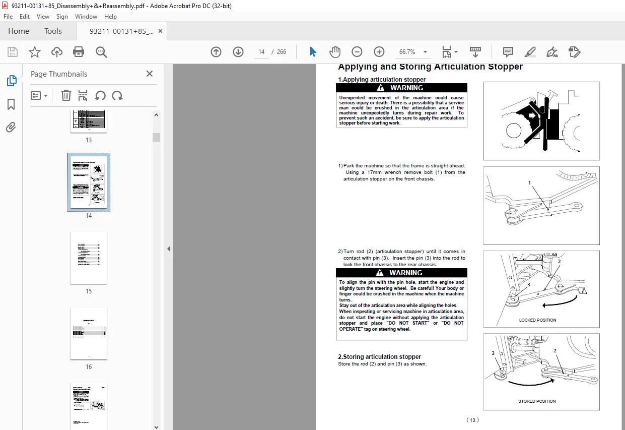
・Be sure to apply the articulation stopper before starting work.
・While supporting the bottom of the chassis using a jack, be sure to support the chassis using the blocks.
・When the boom or bucket is raised or when a unit is lifted by a crane, be sure to place a stand or adequate
cribbing under the unit to prevent unexpected dropping.
・Do not start to work in an enclosed area if adequate ventilation is not provided.
・To remove a heavy unit (20kg or more), be sure to use a crane or other lifting tool.
・Just after stopping operation, be careful not to directly touch a hot component. You may get burned.
・Contact tire manufacturer’s local dealer for tire servicing and changing.
・Always store the tools in good condition, and use them properly.
・Keep the work area clean. Clean up spills immediately.
・Avoid the use of flammable solvents and cleaners.
・When working outdoors keep work areas, ladders, steps, decks and work platforms clear of snow, ice, and mud.
・Use safe work platforms to reach higher areas of the machine.
TABLE OF CONTENTS:
Kawasaki 85ZIV-2 WHEEL LOADER SHOP MANUAL AAA-S85N3E14-00Z – PDF DOWNLOAD
Powered by NISSAN PE6T44 Engine
SERIAL NUMBERS 85N3-9001 and up.
Disassembly& Reassembly
Service standard
FOREWORD 2
Safety Precautions 3
Safety Symbols 4
Symbols 5
Hexagon Bolt Tightening Torque 6
Flanged Hexagon Bolt Tightening Torque 8
Hose Band Tightening Torque 9
Liquid Gasket and Screw Lock Agent 10
Cautions Regarding Welding Repair Service 11
Weight of Main Components 13
Applying and Storing Articulation Stopper 14
CHASSIS GROUP 14 16
Removing and Reinstalling Deck 17
Removing and Reinstalling Fuel Tank 18
Removing and Reinstalling Hydraulic Tank 19
Removing and Reinstalling Engine Room 20
Removing and Reinstalling Cab 23
Removing and Reinstalling Floor Board 26
Removing and Reinstalling Boom 28
Removing and Reinstalling Bushing 31
Center Pin 33
Removing and Reinstalling Center Pin 34
CHASSIS GROUP 15 39
Linkage 40
Linkage Pin Standard Clearance Values 41
Center Pin 42
Bucket 43
Bucket Positioner and Boom Kick-Out 44
POWER GROUP 24 46
Power Line Tightening Torque 47
Radiator Mount Tightening Torque 48
Removing and Reinstalling Radiator 49
Removing and Reinstalling Engine 52
Removing and Reinstalling Propeller Shaft 54
Removing and Reinstalling Air Cleaner 56
Removing and Reinstalling Muffler 58
Front Axle Assembly Tightening Torque 59
Removing and Reinstalling Front Axle Assembly 60
Rear Axle Assembly Tightening Torque 63
Axle Support Tightening Torque 64
Removing and Reinstalling Rear Axle Assembly 65
Disassembling and Reassembling Planetary Assembly 69
Floating Seal 76
Removing and Reinstalling Differential 81
Special Jigs for Disassembling Axle 83
Disassembling and Reassembling Internal Gear Hub 86
Front Differential Tightening Torque 89
Rear Differential Tightening Torque 90
Disassembling and Reassembling Differential Assembly 91
Disassembling and Reassembling Spider Assembly 101
POWER GROUP 25 103
Propeller Shaft Service Standard 104
Axle and Differential Service Standard 105
Axle group 105
Differential 106
TORQUE CONVERTER AND TRANSMISSION GROUP 34 107
Removing and Reinstalling Transmission Assembly 1 Removing transmission assembly 108
Bolt Tightening Torque 115
Disassembling and Reassembling Torque Converter 116
Disassembling and Reassembling Transmission Assembly 123
Disassembling and Reassembling Forward /Reverse Clutch Pack 136
Disassembling and Reassembling 1st/3rd Speed Clutch Pack 140
Disassembling and Reassembling 2nd Speed Clutch Pack 144
Disassembling and Reassembling 4th Speed Clutch Pack 147
Control Valve Tightening Torque 151
Removing and Reinstalling Control Valve 152
Disassembling and Reassembling Control Valve 154
TORQUE CONVERTER AND TRANSMISSION GROUP 35 156
Transmission Assembly 157
Control Valve 158
Gear Pump 160
Clutch Plate Thickness / Piston Stroke 161
Oil Pressure 162
HYDRAULIC GROUP 44 163
Hydraulic Pump 164
Removing and Reinstalling Gear Pump Assembly 165
Steering Valve 167
Removing and Reinstalling Steering Valve 168
Disassembling and Reassembling Steering Valve 170
Multiple Control Valve 174
Removing and Reinstalling Multiple Control Valve 175
Disassembling and Reassembling Multiple Control Valve 178
Boom Cylinder 186
Removing and Reinstalling Boom Cylinder 187
Bucket Cylinder 189
Removing and Reinstalling Bucket Cylinder 190
Steering Cylinder 193
Removing and Reinstalling Steering Cylinder 194
Hydraulic Cylinder Tightening Torque 196
Disassembling and Reassembling Hydraulic Cylinder 197
Pilot Valve 202
Pilot Valve Tightening Torque 203
Removing and Reinstalling Pilot Valve 204
Disassembling and Reassembling Pilot Valve 206
HYDRAULIC GROUP 45 210
Steering Linkage 211
Multiple Control Valve 213
Hydraulic Cylinder 214
Pilot Valve 215
BRAKE GROUP 54 216
Brake Valve Assembly 217
Removing and Reinstalling Brake Valve 218
Disassembling and Reassembling Brake Valve 219
Air Master Tightening Torque 221
Removing and Reinstalling Air Master 222
Disassembling and Reassembling Air Master 223
Auto-Adjuster Valve 229
Removing and Reinstalling Auto-Adjuster Valve 230
Auto-Adjuster Valve Tightening Torque 231
Disassembling and Reassembling Auto-Adjuster Valve 232
Removing and Reinstalling Service Brake 233
Air Cylinder for Parking 234
Removing and Reinstalling Cylinder 235
Disassembly and Reassembly of Air Cylinder 236
Removing and Reinstalling Parking Brake 238
BRAKE GROUP 55 241
Brake Valve 242
Air Master 244
Auto-Adjuster Valve 245
Service Brake 246
Parking Brake 247
ELECTRICAL GROUP 64 248
Removing and Reinstalling Wiper Motor 249
Removing and Reinstalling Controller 253
Removing and Reinstalling Fuse 254
OPERATOR STATION GROUP 74 255
Air Conditioner 256
Air conditioner mount 256
Removing and installing of air conditioner 257
Condenser mount 259
Condenser unit 259
Removing and installing of condensers 260
Compressor mount 261
Removing and installing of compressor Removing the compressor 262
OPERATOR STATION GROUP 75 263
Air Conditioner 264
S.M 6/2/2025