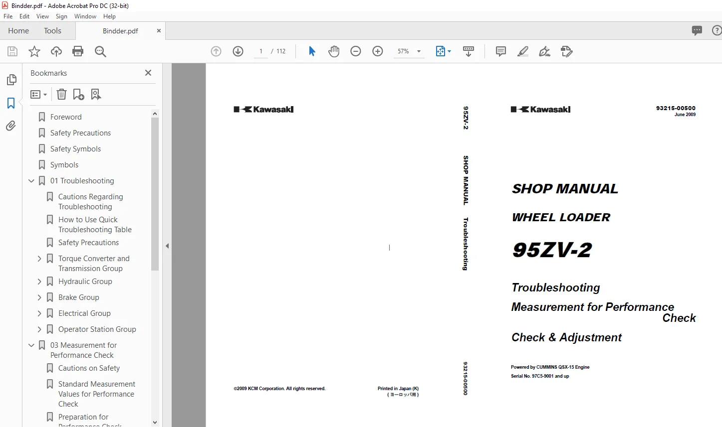
Kawasaki 95ZV-2 Wheel Loader Shop Manual 93215-00500 – PDF DOWNLOAD
$27.95
Kawasaki 95ZV-2 Wheel Loader Shop Manual 93215-00500 – PDF DOWNLOAD
Troubleshooting
Measurement for Performance
Check
Check & Adjustment
Powered by CUMMINS QSX-15 Engine
Serial No. 97C5-9001 and up
Description
Kawasaki 95ZV-2 Wheel Loader Shop Manual 93215-00500 – PDF DOWNLOAD
FILE DETAILS:
Kawasaki 95ZV-2 Wheel Loader Shop Manual 93215-00500 – PDF DOWNLOAD
Language :English
Pages :112
Downloadable : Yes
File Type : PDF
IMAGES PREVIEW OF THE MANUAL:
DESCRIPTION:
Kawasaki 95ZV-2 Wheel Loader Shop Manual 93215-00500 – PDF DOWNLOAD
Troubleshooting
Measurement for Performance
Check
Check & Adjustment
Powered by CUMMINS QSX-15 Engine
Serial No. 97C5-9001 and up
Foreword
- To ensure good machine performance, reduce failures or problems, and prolong the service life of
each component, it is necessary to operate the machine as is directed in the Operation and
Maintenance Manual. - To effectively diagnose and repair the machine, it is important to follow the guidelines laid out
in this Shop Manual.
Measurement for Performance check
- For the engine, refer to the engine Shop Manual provided by the engine manufacturer.
- The purpose of this manual is to provide information on the product and the correct maintenance and
repair meth- ods. Please read this manual to ensure correct troubleshooting and good repair
service. - This manual will be periodically reviewed and revised for more satisfactory content. If you have
any opinion or requests, please inform us.
Safety Precautions
The most important point in providing repair service is safety. To ensure safety, observe the general cautions
described below.
– This manual is intended for properly trained and equipped service technicians.
– Any work on the machine must be performed by the trained personnel only.
– Carefully read this manual to thoroughly understand the operation method before you operate or repair the
machine.
– Be sure to wear appropriate clothes and protectors, such as safety boots, hard hat and goggles.
– Place the machine on level and solid ground, and place chocks against the wheels to prevent movement.
– Remove the cable from the battery before starting the service work, and attach a “DO NOT OPERATE!” tag to the
steering wheel.
– Be sure to release the internal pressure before you remove a pipe, such as the hydraulic oil, air, or engine coolant
pipe.
– Be sure to apply the articulation stopper before starting work.
– While supporting the bottom of the chassis using a jack, be sure to support the chassis using the blocks.
– When the boom or bucket is raised or when a unit is lifted by a crane, be sure to place a stand or adequate cribbing
under the unit to prevent unexpected dropping.
– Do not start to work in an enclosed area if adequate ventilation is not provided.
– To remove a heavy unit (20 kg (40 lbs) or more), be sure to use a crane or other lifting device.
– Just after stopping operation, be careful not to directly touch a hot component. You may get burned.
– Contact tire manufacturer’s local dealer for tire servicing and changing.
– Always store the tools in good condition, and use them properly.
– Keep the work area clean. Clean up spills immediately.
– Avoid the use of flammable solvents and cleaners.
– When working outdoors keep work areas, ladders, steps, decks and work platforms clear of snow, ice, and mud.
– Use safe work platforms to reach higher areas of the machine
TABLE OF CONTENTS:
Kawasaki 95ZV-2 Wheel Loader Shop Manual 93215-00500 – PDF DOWNLOAD
Troubleshooting
Measurement for Performance
Check
Check & Adjustment
Powered by CUMMINS QSX-15 Engine
Serial No. 97C5-9001 and up
Foreword 2
Safety Precautions 3
Safety Symbols 4
Symbols 5
01 Troubleshooting 8
Cautions Regarding Troubleshooting 10
How to Use Quick Troubleshooting Table 11
Safety Precautions 12
Torque Converter and Transmission Group 13
1 Machine dose not move in any shift lever position 13
2 Machine dose not move at a certain shift lever position (OR:Machine moves only in a certain shift lever position) 14
3 Machine moves at the neutral position (Example: Machine moves forward at the neutral position) 15
4 Large shock at starting or changing speed / direction 16
5 Large time lag at starting or changing speed / direction 17
6 Low power (Defective torque converter or transmission) 18
7 Torque converter oil is overheating 19
8 Machine moves reverse when starting to climb up on a slope using inching brake 20
9 Automatic speed change is not possible 21
10 Downshift button does not work 22
Hydraulic Group 23
1 Boom and/or bucket do not move 23
2 Boom and/or bucket have low power, or move too slowly 24
3 Excessive cylinder drift 25
4 Boom and/or bucket are spongy (Holding bucket against the ground is not possible-front wheels off the ground) 26
5 Bucket leveler does not work Boom lift kickout and lower kickout does not work 27
6 Steering is not possible or hard to steer 28
7 Machine sways, or has a shock during steering 29
8 ELS (Efficient Loading System) does not work (Excavating and scooping tractive power does not become up during ELS working condition) 30
9 Ride control does not work 31
10 Fan motor rotates abnormally or does not rotate 32
11 Abnormal noise in hydraulic system 33
12 Others 34
Brake Group 35
1 Brake does not work well (In the worst case, the brake does not work at all) 35
2 Brake is dragging when released 36
3 Stepping on the brake pedal sounds the buzzer 37
4 Accumulator pressure does not rise, or too slow in rising 38
5 Parking brake does not work (or: Releasing the parking brake is not possible) 39
Electrical Group 40
1 Instrument panel does not indicate properly 40
2 Fuse for controller is blown 41
Error code (for chassis) 42
Error code (for engine) 45
Operator Station Group 51
Air conditioner 51
03 Measurement for Performance Check 60
Cautions on Safety 61
Standard Measurement Values for Performance Check 62
Preparation for Performance Check 65
Engine 67
Measuring engine speed 67
Measurement instrument 67
Standard measurement value 67
Clutch Oil Pressure and Time Lag 71
Measuring clutch oil pressure 71
Measurement instrument 71
Gauge port 71
Standard measurement value 72
Clutch oil pressure measurement procedure 72
Time lag measurement procedure 73
Possible causes for low clutch pressure and clutch time lag 73
Hydraulic Cylinder 74
Cylinder natural drift 74
Measurement instrument 74
Standard measurement value (mm/min) (in/min) 74
Measurement procedure 74
Possible causes of excessive cylinder drift 75
Boom Cycle Time 76
Measurement instrument 76
Warm-up the engine before measuring boom rising time 76
Standard measurement value (sec) 76
Measurement procedure 76
Full Steering Time 78
Measurement instrument 78
Warm-up the engine before measuring full steering time 78
Standard measurement value (sec) 78
Measurement procedure 78
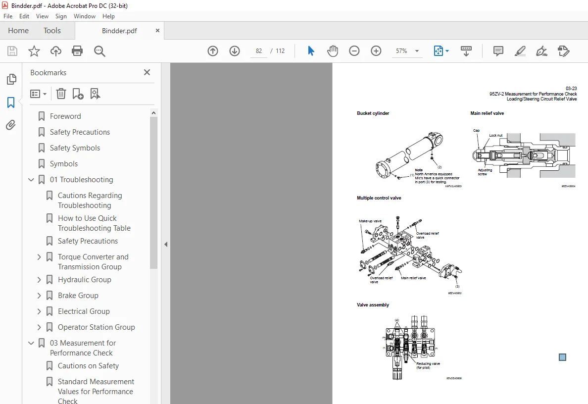
Loading/Steering Circuit Relief Valve 80
Loading circuit relief valve setting pressures 80
Measurement instruments 80
Gauge port 80
Standard measurement value MPa (kgf/cm2) (psi) 81
Measuring loading circuit main relief pressure 81
Measuring loading circuit overload relief pressure 83
Measuring pilot circuit relief pressure 84
Steering circuit relief valve setting pressures 85
Measurement instruments 85
Gauge port 85
Standard measurement value MPa (kgf/cm2) (psi) 86
Measuring steering circuit main relief pressure 86
Measuring steering circuit overload relief pressure 88
Measuring pilot circuit relief pressure (reducing pressure) 89
Stop Valve 91
Stop valve adjustment procedure 91
Fan Revolution 92
Measurement instrument 92
Measuring number of fan maximum revolutions 92
Service Brake 93
Service brake performance check 93
Condition 93
Standard measurement value 93
Parking Brake 94
Parking brake performance check 94
Condition 94
Standard measurement value 94
Brake Circuit Oil Pressure 95
Unloader valve setting pressure 95
Measurement instrument 96
Gauge port 96
Standard measurement value 96
Measurement procedure 96
Brake valve oil pressure 98
Brake valve performance 99
Accumulator Circuit Charging Time100
Measurement instrument100
Gauge installation position100
Standard measurement valve (sec)101
Measurement procedure101
Number of Brake Pedal Applications102
Standard measurement value102
Measurement procedure102
Possible causes of extremely low measurement value and solution102
Declutch Engagement103
Measurement instrument103
Warm-up the engine before measuring declutch engagement103
Standard measurement value103
Cause of extremely high measurement value and solution103
Measurement procedure103
Maintenance Log105
Notes109
S.M 4/2/2025