Kawasaki Kcm 80ZV-2 WHEEL LOADER SHOP MANUAL 93209-00442 – PDF DOWNLOAD
$30.95
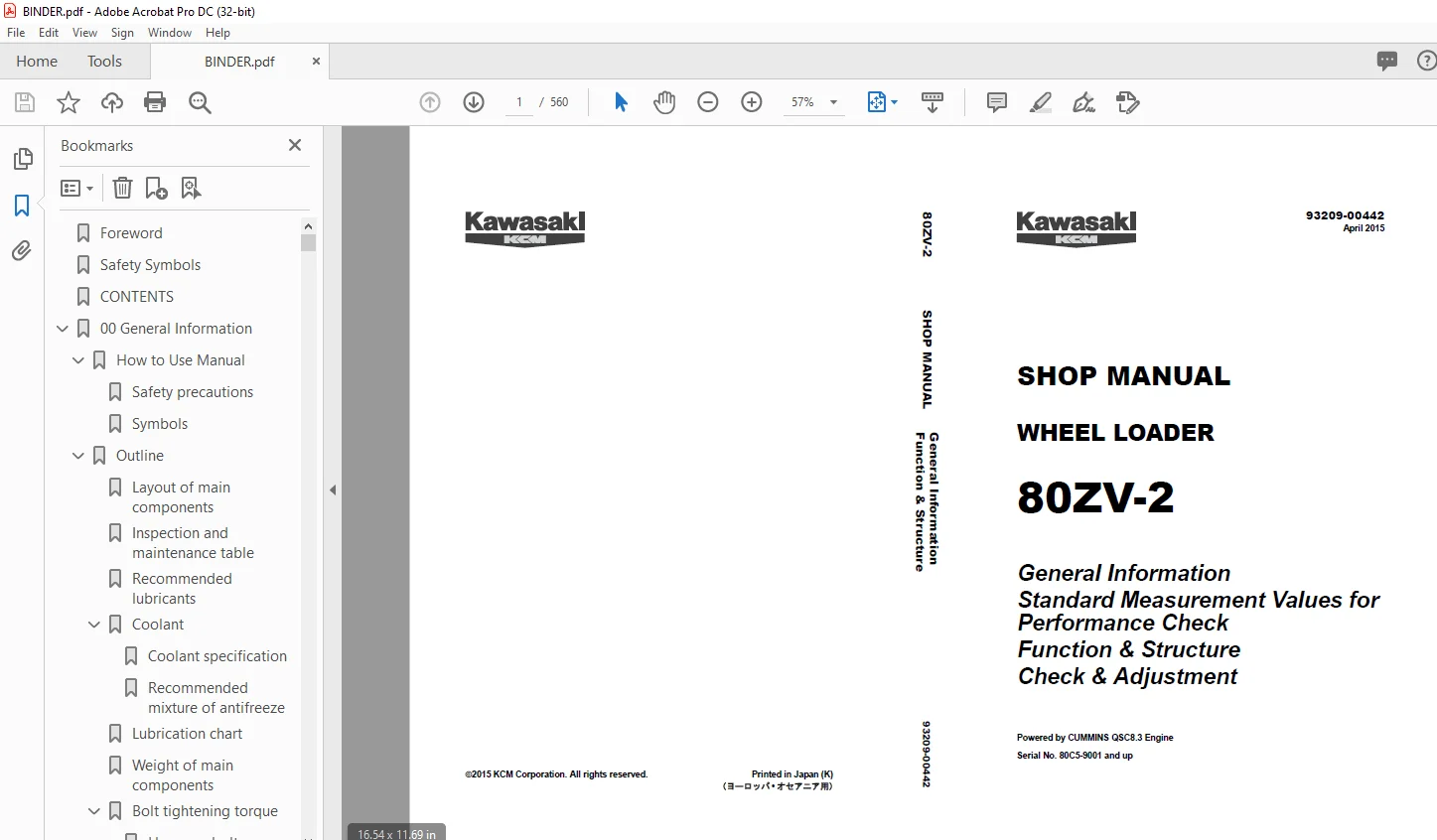
Kawasaki Kcm 80ZV-2 WHEEL LOADER SHOP MANUAL 93209-00442 – PDF DOWNLOAD
General Information
Standard Measurement Values for
Performance Check
Function & Structure
Check & Adjustment
Powered by CUMMINS QSC8.3 Engine
Serial No. 80C5-9001 and up
Description
Kawasaki Kcm 80ZV-2 WHEEL LOADER SHOP MANUAL 93209-00442 – PDF DOWNLOAD
FILE DETAILS:
Kawasaki Kcm 80ZV-2 WHEEL LOADER SHOP MANUAL 93209-00442 – PDF DOWNLOAD
Language :English
Pages :560
Downloadable : Yes
File Type : PDF
IMAGES PREVIEW OF THE MANUAL:
DESCRIPTION:
Kawasaki Kcm 80ZV-2 WHEEL LOADER SHOP MANUAL 93209-00442 – PDF DOWNLOAD
General Information
Standard Measurement Values for
Performance Check
Function & Structure
Check & Adjustment
Powered by CUMMINS QSC8.3 Engine
Serial No. 80C5-9001 and up
Foreword’
- To ensure good machine performance, reduce failures or problems, and prolong the service life of each component, it is necessary to operate the machine as is directed in the Operator and Maintenance Manual.
- To effectively diagnose and repair the machine, it is important to follow the guidelines laid out in this Shop Manual. General Information Function and structure For the engine, refer to the engine Shop Manual provided by the engine manufacturer.
- The purpose of this manual is to provide information on the product and the correct maintenance and repair methods. Please read this manual to ensure correct troubleshooting and good repair service. This manual will be periodically reviewed and revised for more satisfactory content. If you have any opinion or requests, please inform us.
TABLE OF CONTENTS:
Kawasaki Kcm 80ZV-2 WHEEL LOADER SHOP MANUAL 93209-00442 – PDF DOWNLOAD
General Information
Standard Measurement Values for
Performance Check
Function & Structure
Check & Adjustment
Powered by CUMMINS QSC8.3 Engine
Serial No. 80C5-9001 and up
Foreword 2
Safety Symbols 3
CONTENTS 4
00 General Information 16
How to Use Manual 17
Safety precautions 17
Symbols 18
Outline 19
Layout of main components 19
Inspection and maintenance table 20
Recommended lubricants 23
Coolant 25
Coolant specification 25
Recommended mixture of antifreeze 25
Lubrication chart 26
Weight of main components 27
Bolt tightening torque 28
Hexagon bolt 28
Flanged hexagon bolt 31
Hose band tightening torque 32
Liquid gasket and screw lock agent 33
Cautions regarding parts removal 33
Cautions regarding reassembly 33
Screw lock agent application procedure 34
How to wind a seal tape 34
Cautions regarding welding repair service 35
03 Measurement for Performance Check 38
Cautions on Safety 39
Standard Measurement Values for Performance Check 40
12 Function & Structure Chassis Group 44
Front Chassis 45
Loading linkage 45
Loading linkage pin 47
Rear Chassis 48
Fuel tank (S/N 9001~9128) 48
Fuel tank (S/N 9129~) 49
Floor board mount 50
Floor board 50
Viscous mount 50
Center Pin 51
Upper center pin 51
Lower center pin 51
Dust seal 52
13 Check & Adjustment Chassis Group 54
Linkage Pin 55
Liner 55
Adjustment 56
Center Pin 57
Adjusting shim 57
Installing bearing cover 57
Installing bearing outer ring 58
22 Function & Structure Power Group 60
Power Line 61
Engine / Transmission 62
Engine / transmission mount 62
Radiator (S/N 9001~9100) 63
Radiator mount 64
Radiator (S/N 9101~) 65
Radiator mount 66
Propeller Shaft 67
Second propeller shaft assembly 68
Front differential – Transmission 68
Third propeller shaft assembly 69
Transmission – Rear differential 69
Axle Assembly 70
Axle Support 71
Differential Gear 73
Torque proportioning type 73
Function of TPD 75
Operation of TPD 76
Limited Slip Differential (option) 77
LSD structure 77
LSD function 80
LSD operation 80
23 Check & Adjustment Power Group 82
Engine 83
Measuring engine speed 83
Measurement instrument 83
Standard measurement value 83
Measuring engine oil pressure 83
Measurement instrument 83
Install position 83
Standard measurement value 83
Propeller Shaft 84
Propeller shaft phase 84
Second propeller shaft alignment 84
Tightening torque 85
Axle 86
Axle nut tightening procedure 86
Differential gear adjustment procedure 87
Preload adjustment 88
Bearing installation 88
Oil seal installation 88
Adjusting tooth contact 89
32 Function & Structure Torque Converter and Transmission Group 92
Torque Converter 93
Torque converter structure 93
Power flow path 93
Torque multiplication 93
Torque Converter Gear Pump 94
Gear pump specifications 94
Transmission 95
Clutch combination 95
Shift lever position 95
Downshift button operation 95
Gear train and number of teeth 96
Clutch specifications 97
Friction plate: mm (in) 97
Clutch Pack 98
Forward and 3rd speed clutches 98
Reverse and 2nd speed clutches 99
1st speed clutch100
4th speed clutch101
Power Flow Path in the Transmission102
Forward 1st speed power flow path102
Forward 2nd speed power flow path102
Forward 3rd speed power flow path103
Forward 4th speed power flow path103
Reverse 1st speed power flow path104
Reverse 2nd, 3rd, and 4th speeds power flow paths104
Hydraulic System Diagram105
Hydraulic Circuit Diagram106
Oil Flow107
Oil flow in the torque converter line107
From torque converter gear pump to torque converter107
From torque converter to cooling circuit107
From cooler to lubrication circuit107
Oil flow to the clutch107
To forward and reverse clutches107
To speed clutch107
T/C and T/M Oil Circulation108
Control Valve110
System diagram111
Modulation Mechanism112
Clutch control oil pressure curve113
Traveling at forward 1st speed114
Pressure holding114
Changing from forward 1st speed to reverse 1st speed115
Releasing forward clutch and feeding initial oil to reverse clutch115
Trimmer engagement116
Low-pressure holding116
Clutch engagement starting117
Pressure increase117
Clutch Solenoid Valve118
For forward/reverse and speed clutches118
After power-off (clutch disengaged status)118
After power-on (clutch engaged status)119
For trimmer120
After power-off (high clutch pressure status)120
After power-on (just after switching clutch)121
33 Check & Adjustment Torque Converter and Transmission Group122
Clutch Oil Pressure123
Measuring clutch oil pressure123
42 Function & Structure Hydraulic Group124
Flushing Hydraulic Circuit125
Purpose of flushing125
Cautions on Hydraulic Parts Replacement126
Hydraulic Circuit Symbols127
Hydraulic lines127
Pumps & motors127
Cylinders127
Operation methods128
Pressure control valve128
Flow control valve128
Directional control valve129
Check valve129
Miscellaneous hydraulic symbols130
Hydraulic System Operation131
Hydraulic system operation outline131
Loading system131
Steering system131
Efficient loading system132
Fan motor system132
Ride control system (OPT)132
Layout of Hydraulic Units133
Hydraulic Tank134
Hydraulic tank specifications134
Hydraulic oil level check134
Hydraulic Tank (S/N 9001~9250)135
Hydraulic tank breather valve (tank cap) (S/N ~9250)136
Hydraulic Tank (S/N 9251~)137
Hydraulic tank breather valve (tank cap) (S/N 9251~)138
Hydraulic Pump139
Hydraulic pump specifications139
Hydraulic pump principle140
Hydraulic pump wear plate141
Hydraulic pump bushing lubrication141
Hydraulic Cylinder142
Boom cylinder142
Bucket cylinder142
Steering cylinder143
Hydraulic cylinder specifications144
Loading System145
Reducing Valve (for Pilot Pressure)146
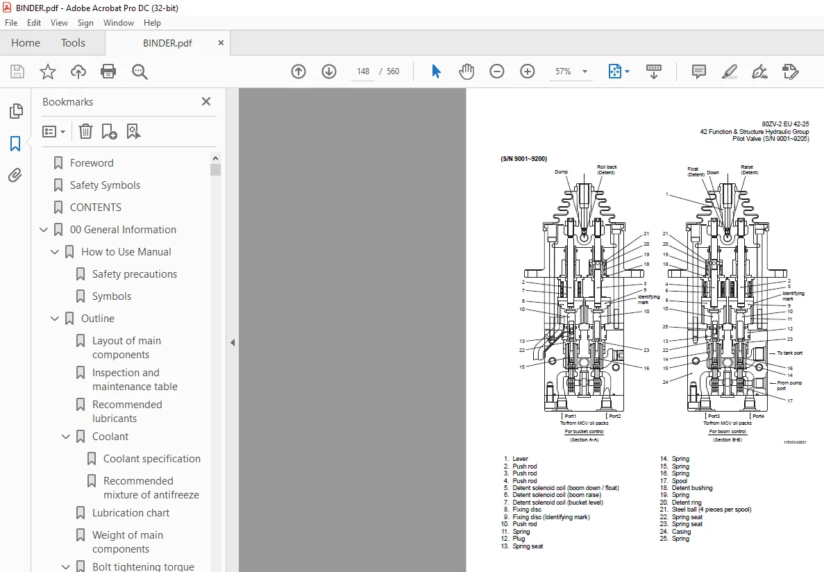
Pilot Valve (S/N 9001~9205)147
Pilot valve function150
Pilot valve operation (modulated position)150
Pre-detent and detent magnet solenoid152
Pilot Valve (S/N 9206~)153
Pilot valve function155
Pilot valve operation (modulated position)155
Pre-detent and detent magnet solenoid157
Multiple Control Valve (KML28/2T102)158
Multiple control valve specifications159
Multiple control valve main relief valve160
Main relief valve operation160
Adjusting set pressure161
Multiple control valve overload relief valve (with make-up function)161
Overload relief valve operation162
Make-up valve operation162
Adjusting set pressure163
Multiple control valve make-up valve163
Make-up valve operation163
Multiple control valve bucket spool164
Bucket spool operation164
Multiple control valve boom spool166
Boom spool operation166
Adapter (Orifice)169
Ride Control (OPT)170
Ride control hydraulic circuit170
Ride control function170
Ride control operation171
Preparation mode (ride control switch is OFF)171
Running mode (ride control switch is ON)172
Ride control valve assembly173
Solenoid valve176
Accumulator (for ride control)178
Accumulator function178
Steering System179
Orbitrol®180
Orbitrol® structure180
Valve part180
Rotor part181
Orbitrol® specification181
Orbitrol® operation182
Neutral182
Turn183
Orbitrol® feed-back mechanism operation184
Steering speed and flow rate control185
Hydraulic pump oil amount and steering force185
Orbit rotor operation principle186
Steering Valve (KVS25-A30/20)187
Steering valve operation189
Neutral position (steering spool in “Neutral”)189
Left turn position190
Steering plunger variable throttle191
Steering valve flow control plunger192
Steering valve main relief valve193
When the pressure is at the preset value or less193
When the pressure exceeds the preset value194
Steering valve overload relief valve195
Overload relief valve operation196
Make-up valve operation196
Steering pilot circuit and its operation197
Flow amplifier notch and pilot orifice198
Stop Valve199
Stop valve function200
Stop valve operation200
Reducing Valve (for Orbitrol®)201
Steering Line Filter202
K-Lever (OPT)203
Hydraulic circuit203
Hydraulic line diagram204
Hydraulic line205
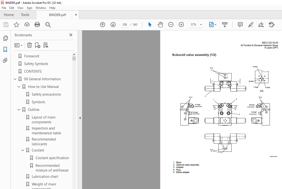
Solenoid valve assembly (1/2)206
Solenoid valve assembly (2/2)207
Adjustment method207
Efficient Loading System208
Efficient loading system outline208
The operation condition of ELS208
Mounting of the ELS valve209
Mounting of the variable kickout sensor210
Efficient loading system operation211
While the ELS is not operating211
While the ELS is operating211
Fan Motor System212
Mounting of fan motor212
Fan Motor Line213
Hydraulic circuit (fan motor normal rotation)215
Safety valve (with suction function)215
Flow control valve216
Flow control solenoid valve217
Fan motor218
Reversing Fan Motor Line (OPT)221
Reversing fan motor function221
Fan motor222
Reversing fan control chart224
Hydraulic circuit (Reverse rotation)225
Secondary Steering226
Secondary steering operation227
Secondary steering motor and pump228
43 Check & Adjustment Hydraulic Group230
Loading/Steering Circuit Relief Valve/Ride Control Circuit Reducing Valve (OPT)231
Loading circuit relief valve setting pressures231
Measuring loading circuit main relief pressure233
Measuring loading circuit overload relief pressure234
Measuring pilot circuit relief pressure235
Ride control circuit reducing valve setting pressures (OPT)236
Measuring ride control circuit reducing pressure237
Steering circuit relief valve setting pressures238
Measuring steering circuit main relief pressure240
Measuring steering circuit overload relief pressure241
Measuring pilot circuit relief pressure (reducing pressure)242
Hydraulic Cylinder243
Cylinder natural drift243
Stop Valve245
Stop valve adjustment procedure245
52 Function & Structure Brake Group246
Brake System Outline247
Service brake247
Parking brake247
Adjustment of axle internal pressure247
Brake Units Layout248
Unloader Valve249
Unloader valve operation251
Valve Unit252
Accumulator low pressure sensor253
Accumulator254
In-Line Filter255
Brake Valve256
Brake valve performance chart257
Brake valve outline258
While the valve is not operating258
While the valve is operating259
While the valve is releasing259
Service Brake260
Service brake operation260
Service brake friction plate261
Service brake steel plate261
Brake circuit air bleeding procedure262
Bleeding air from brake pipes and axle housing hubs262
Parking Brake263
Parking brake operation264
Parking brake solenoid valve265
Solenoid valve operation265
Solenoid valve specifications265
Parking Brake Manual Release266
Parking Brake Spring Chamber268
Brake Circuit Check Valve269
Pressure Sensor (for stop lamp and declutch)270
Pressure sensor (for declutch)270
Pressure sensor (for stop lamp)270
53 Check & Adjustment Brake Group274
Brake Circuit Oil Pressure275
Unloader valve setting pressure275
Unloader valve setting pressure measurement276
Brake valve oil pressure277
Brake valve oil pressure measurement277
Brake valve performance278
Service Brake279
Service brake performance check279
Service brake friction plate wear measurement280
Cautions on installing brake discs281
Parking Brake282
Parking brake performance check282
Parking brake clearance adjustment283
Adjustment procedure284
Brake lining abrasion check284
62 Function & Structure Electrical Group286
How to Use Electrical Wiring Diagram287
Utilisation des schémas des câblages électriques (FRANÇAIS)288
Verwendung des elektrischen Schaltplans (DEUTSCH)289
Modalità di utilizzo dello schema dei collegamenti elettrici (ITALIANO)290
Cómo utilizar un Diagrama de Alambrado Eléctrico (ESPAÑOL)291
Como Utilizar o Diagrama de Ligações Eléctricas (PORTUGUÊS)292
Electrical Cable Color Codes293
Electrical Circuit Symbols294
Sensor Mount295
Fuse296
Fuse box296
Fusible link298
Engine Start Circuit299
Engine start circuit diagram299
Neutral starter299
Shift lever neutral (N) position299
Shift lever forward/reverse (F/R) position300
Starter switch301
ECM safety features302
Battery relay302
Battery relay operation302
Alternator R terminal wire303
Diode unit303
Neutral relay304
Magnetic switch305
Voltage relay306
Power Generating/Charging Circuit307
Alternator307
ECM (Engine Controller)308
Function of ECM308
Connection diagram308
Monitor lamp test309
Failure diagnosis310
Engine diagnostic switch (option)310
Failure diagnostic chart311
Increment decrement switch (option)312
Quantum fault code information313
Accelerator pedal319
Accelerator pedal installation321
Transmission Control Circuit and Monitor Circuit322
Machine control unit (MCU)322
Connector323
Machine control unit (MCU) connection diagram (S/N 9001~9350)324
Machine control unit (MCU) connection diagram (S/N 9351~)326
Machine control unit (MCU) function328
Forward/reverse (F/R) shifting and speed change328
Automatic shift330
Machine speed sensor331
Switching from automatic to manual332
Downshift button operation332
Adjustable declutch preset switch333
Back-up alarm334
Parking brake335
Machine control unit (MCU) failure warning337
Secondary steering function338
Monitoring system340
Items to be monitored and operation condition340
Operation monitor lamps341
Instrument Panel and Switch342
Instrument panel342
Instrument panel rear surface344
Gauge circuit346
Fuel level sensor348
MODM350
MODM function350
Monitor Changeover350
Changing display from one function to next351
Information Monitor353
Information monitor display353
Unit conversion and language selection356
Replacement Monitor357
Replacement time check357
Replacement interval set (timer reset)361
Replacement interval pop-up362
Display language363
Fault Log Monitor363
Fault log history check363
Selection of machine fault log and engine fault log364
Machine fault log navigation365
Engine fault log navigation365
Clear fault log365
Clear active fault log (error pop up) (S/N 9001~9101, 9103, 9104 only)366
Input/Output Monitor370
Input/Output monitor display370
Parameter Setting Monitor374
Parameter setting monitor display374
Parameter change382
Specification Setting Monitor383
Specification setting monitor display383
All setting reset386
Electrical Detent Circuit389
Bucket leveler389
Proximity switch389
Detent solenoid390
Lift kickout & lower kickout391
Location391
Lift kickout391
Lower kickout392
Sensor assy393
Detent solenoid395
Preset height adjustment395
Diode396
Diode check method397
Caution for diode check method397
Continuity check mode397
Diode check mode397
Resistance check mode398
Surge voltage and surge suppression diodes399
72 Function & Structure Operator Station Group400
Cabin401
Glass402
Wiper mount405
Front wiper405
Rear wiper405
Wiper motor406
Operator Seat408
Steering and Transmission Shift Lever409
Tilt case410
Column shaft411
Shift lever411
Air Conditioner412
Denso air conditioner components412
Air conditioner specifications (system performance)412
Denso air conditioner structure413
Cooling unit413
Heater and accessories415
Air distributor (hood & defroster selection box)415
Air compressor (with magnetic clutch)416
Condenser unit416
Control unit417
Function of cooling mechanism418
Principle of cooling418
Refrigerant419
Refrigerant characteristics420
Cooling circuit421
Electrical circuit422
Control schematic drawing422
Air conditioner functions of components423
Control panel423
Air conditioner unit430
Compressor and magnetic clutch439
Condenser unit442
Receiver dryer444
Sight glass446
Pressure switches446
Pressure relief valve448
Relay A449
Relay B449
Refrigerant hose450
Charge of refrigerant451
Work procedure452
Refrigerant charging tools454
Refrigerant charging procedure457
Troubleshooting using the gauge manifold463
Air conditioner troubleshooting468
Fault diagnosis procedure468
73 Check & Adjustment Operator Station Group476
Air Conditioner477
Adjustment of lubricating oil quantity when components of air conditioner are replaced477
When the compressor is replaced478
When the evaporator is replaced479
When the condenser is replaced479
Adjustment of air gap (between hub and rotor) in compressor magnetic clutch480
Compressor V-belt adjustment481
Belt adjustment procedure482
Belt adjustment value482
Parts to be replaced periodically483
Air filters483
Receiver dryer483
INDEX484
Maintenance Log491
Notes495
92 Drawing & Diagrams499
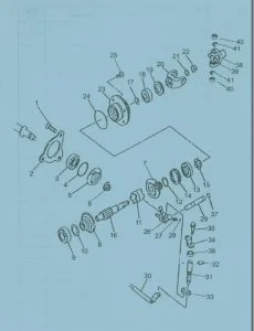
Axle Assembly500
Torque Converter and Transmission501
Hydraulic & Brake Circuit502
Brake Circuit503
Electrical Wiring Diagram (1/3) (S/N 9001~9038)504
Electrical Wiring Diagram (2/3) (S/N 9001~9038)505
Electrical Wiring Diagram (3/3) (S/N 9001~9038)506
Electrical Wiring Diagram (1/3) (S/N 9039~9100)507
Electrical Wiring Diagram (2/3) (S/N 9039~9100)508
Electrical Wiring Diagram (3/3) (S/N 9039~9100)509
Electrical Wiring Diagram (1/3) (S/N 9101~9200)510
Electrical Wiring Diagram (2/3) (S/N 9101~9200)511
Electrical Wiring Diagram (3/3) (S/N 9101~9200)512
Electrical Wiring Diagram (1/3) (S/N 9201~9350)513
Electrical Wiring Diagram (2/3) (S/N 9201~9350)514
Electrical Wiring Diagram (3/3) (S/N 9201~9350)515
Electrical Wiring Diagram (1/3) (S/N 9351~)516
Electrical Wiring Diagram (2/3) (S/N 9351~)517
Electrical Wiring Diagram (3/3) (S/N 9351~)518
Electrical Wiring Diagram519
Way of looking at connectors519
Electrical wiring diagram abbreviation chart521
Electrical Wiring Diagram (CAB)523
Electrical Connection Diagram (1/2) (S/N 9001~9100)526
Electrical Connection Diagram (2/2) (S/N 9001~9100)527
Electrical Connection Diagram (1/2) (S/N 9101~9200)528
Electrical Connection Diagram (2/2) (S/N 9101~9200)529
Electrical Connection Diagram (1/2) (S/N 9201~9350)530
Electrical Connection Diagram (2/2) (S/N 9201~9350)531
Electrical Connection Diagram (1/2) (S/N 9351~)532
Electrical Connection Diagram (2/2) (S/N 9351~)533
Electrical Wiring Diagram (Cabin Air Conditioner)534
Electrical Circuit Diagram (Cabin Air Conditioner)535
Equipment Operation Table (Cabin Air Conditioner)536
Electrical Equipment Layout537
Electrical Equipment Layout (K-Lever)550
Outline of MODM (Machine Operation Diagnostic Module) Operation551
MODM: Input/Output Monitor – Input/Output Signal Correspondence Table560
S.M 3/2/2025