Kawasaki KCM WHEEL LOADER 65ZV-2 SHOP MANUAL 93207-00851 – PDF DOWNLOAD
$30.95
Kawasaki KCM WHEEL LOADER 65ZV-2 SHOP MANUAL 93207-00851 – PDF DOWNLOAD
General Information
Standard Measurement Values for
Performance Check
Function & Structure
Check & Adjustment
Powered by Isuzu 4HK1X Engine
Serial No. 65J4-5001 and up
Description
Kawasaki KCM WHEEL LOADER 65ZV-2 SHOP MANUAL 93207-00851 – PDF DOWNLOAD
FILE DETAILS:
Kawasaki KCM WHEEL LOADER 65ZV-2 SHOP MANUAL 93207-00851 – PDF DOWNLOAD
Language :English
Pages :560
Downloadable : Yes
File Type : PDF
IMAGES PREVIEW OF THE MANUAL:
DESCRIPRION:
Kawasaki KCM WHEEL LOADER 65ZV-2 SHOP MANUAL 93207-00851 – PDF DOWNLOAD
General Information
Standard Measurement Values for
Performance Check
Function & Structure
Check & Adjustment
Powered by Isuzu 4HK1X Engine
Serial No. 65J4-5001 and up
Foreword
- To ensure good machine performance, reduce failures or problems, and prolong the service life of each component,it is necessary to operate the machine as is directed in the Operator and Maintenance Manual.
- To effectively diagnose and repair the machine, it is important to follow the guidelines laid out in this Shop Manual.
Function and structure
- For the engine, refer to the engine Shop Manual provided by the engine manufacturer.
- The purpose of this manual is to provide information on the product and the correct maintenance and repair methods.Please read this manual to ensure correct troubleshooting and good repair service.
- This manual will be periodically reviewed and revised for more satisfactory content. If you have any opinion orrequests, please inform us.
Safety Symbols
An accident may occur if you disregard safety rules. In this manual, several expressions are used according to levels of danger for inspection and repair work as shown below. Read the work procedures and cautions described in this manual, and take preventive measures against possible problems before starting service work.
TABLE OF CONTENTS:
Kawasaki KCM WHEEL LOADER 65ZV-2 SHOP MANUAL 93207-00851 – PDF DOWNLOAD
General Information
Standard Measurement Values for
Performance Check
Function & Structure
Check & Adjustment
Powered by Isuzu 4HK1X Engine
Serial No. 65J4-5001 and up
Foreword 4
Safety Symbols 5
CONTENTS 6
00 General Information 18
How to Use Manual 19
Safety precautions 19
Symbols 20
Outline 21
Layout of main components 21
Inspection and maintenance table 22
Recommended Lubricants 25
Coolant 27
Coolant specification 27
Recommended mixture of antifreeze 27
Lubrication chart 28
Weight of main components 29
Bolt tightening torque 30
Hexagon bolt 30
Flanged hexagon bolt 33
Hose band tightening torque 34
Liquid gasket and screw lock agent 35
Cautions regarding parts removal 35
Cautions regarding reassembly 35
Screw lock agent application procedure 36
How to wind a seal tape 36
Cautions regarding welding repair service 37
03 Measurement for Performance Check 40
Cautions on Safety 41
Standard Measurement Values for Performance Check 42
12 Function & Structure Chassis Group 46
Front Chassis 47
Loading linkage 47
Loading linkage pin 49
Rear Chassis 50
Fuel tank (S/N 5001~5128) 50
Fuel tank (S/N 5129~) 51
Floor board mount 52
Floor board 52
Viscous mount 52
Center Pin 53
Upper center pin 53
Lower center pin 53
Dust seal 54
13 Check & Adjustment Chassis Group 56
Linkage Pin 57
Liner 57
Adjustment 58
Center Pin 59
Adjusting shim 59
22 Function & Structure Power Group 60
Power Line 61
Engine / Transmission 62
Engine / transmission mount 62
Radiator 63
Radiator mount 64
Propeller Shaft 65
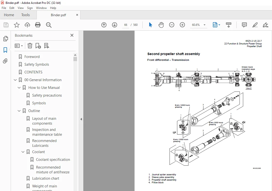
Second propeller shaft assembly 66
Front differential – Transmission 66
Third propeller shaft assembly 67
Transmission – Rear differential 67
Axle Assembly 68
Axle Support 69
Differential Gear 71
Function of TPD 75
Difference in gear shapes 75
Contact between pinion and side gear 75
Operation of TPD 76
Limited Slip Differential (option) 77
LSD function 80
LSD operation 80
23 Check & Adjustment Power Group 82
Engine 83
Measuring engine speed 83
Measuring engine oil pressure 83
Propeller Shaft 84
Propeller shaft phase 84
Second propeller shaft alignment 84
Tightening torque 85
32 Function & Structure Torque Converter and Transmission Group 86
Torque Converter 87
Torque converter structure 87
Power flow path 87
Torque multiplication 87
Torque Converter Gear Pump 88
Pump specifications 88
Transmission 89
Clutch combination 89
Shift lever position 89
Downshift button operation 89
Gear train and number of teeth 90
Valve location 91
Clutch specifications 93
Friction plate: mm (in) 93
Clutch Pack 95
Forward and reverse clutch 95
1st and 2nd speed clutch 96
3rd and 4th speed clutch 97
Power Flow Path in the Transmission 98
Forward 1st speed power flow path 98
Forward 2nd speed power flow path 99
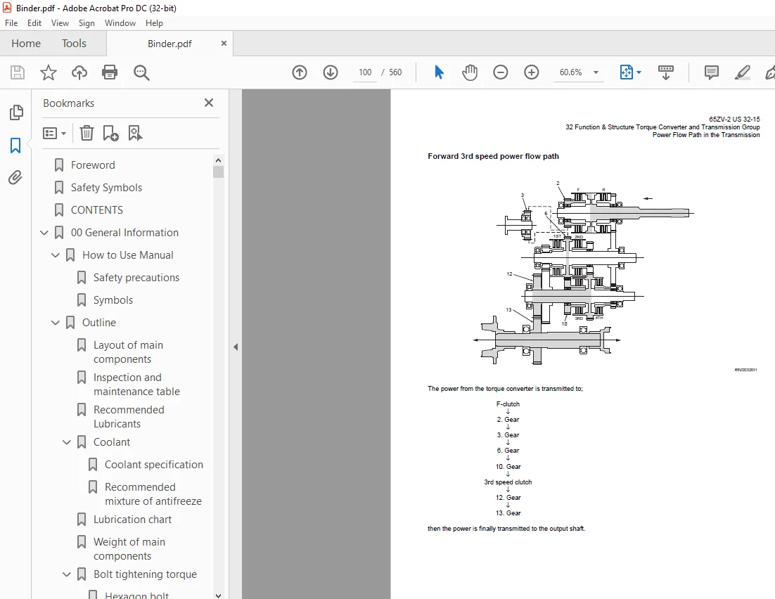
Forward 3rd speed power flow path100
Forward 4th speed power flow path101
Reverse 1st speed power flow path102
Reverse 2nd, 3rd, and 4th speeds power flow path102
Hydraulic System Diagram103
Hydraulic Circuit Diagram104
Oil Flow105
Oil flow in the torque converter line105
From torque converter gear pump to torque converter105
Return oil from torque converter105
Return oil from cooler105
Oil flow to the clutches105
To forward and reverse clutches105
To speed clutches105
T/C and T/M Oil Circulation106
Control Valve108
Main control valve108
3rd, 4th speed control valve108
Oil port layout109
Layout of ports on mounting surface of control valve (at T/M case side)109
Modulation Mechanism110
Clutch control oil pressure curve110
Modulation mechanism operation111
Before the shift lever is moved (traveling or stop condition) (high pressure holding)111
When the shift lever is moved (1) (Initial oil feeding to clutch piston chamber)112
When the shift lever is moved (2) (clutch oil pressure increase)113
Accumulator114
Accumulator for 1st and 2nd speed clutch114
Clutch Solenoid Valve115
For forward/reverse and speed clutches115
After power-off (clutch disengaged status)115
After power-on (clutch engaged status)116
33 Check & Adjustment Torque Converter and Transmission Group118
Clutch Oil Pressure119
Measuring clutch oil pressure119
42 Function & Structure Hydraulic Group122
Flushing Hydraulic Circuit123
Purpose of flushing123
Cautions on Hydraulic Parts Replacement124
Hydraulic Circuit Symbols125
Hydraulic lines125
Pumps & motors125
Cylinders125
Operation methods126
Pressure control valve126
Flow control valve126
Directional control valve127
Check valve127
Miscellaneous hydraulic symbols128
Hydraulic System Operation129
Hydraulic system operation outline129
Loading system129
Steering system129
Fan motor system130
Ride control system (OPT)130
Secondary steering (OPT)130
Layout of Hydraulic Units131
Hydraulic Tank132
Hydraulic Tank (S/N 5001~5200)132
Hydraulic tank breather valve (tank cap)(S/N 5001~5200)133
Hydraulic Tank (S/N 5201~)134
Hydraulic tank breather valve (tank cap)(S/N 5201~)135
Hydraulic tank specifications136
Hydraulic oil level check137
Hydraulic Pump138
Hydraulic pump specifications138
Hydraulic pump principle139
Hydraulic pump wear plate140
Hydraulic pump bushing lubrication140
Hydraulic Cylinder141
Boom cylinder141
Bucket cylinder142
Steering cylinder142
Hydraulic cylinder specifications143
Loading System144
Reducing Valve (for Pilot Pressure)145
Pilot Valve (TH40MS)146
Pilot valve specifications147
Pilot valve performance chart147
Pilot valve operation149
Multiple Control Valve (KML22/2T)151
Multiple control valve specifications152
Multiple control valve main relief valve153
Main relief valve operation153
Adjusting set pressure154
Multiple control valve overload relief valve (with make-up function)155
Overload relief valve operation155
Adjusting set pressure156
Multiple control valve make-up valve157
Make-up valve operation157
Multiple control valve bucket spool158
Bucket spool operation158
Multiple control valve boom spool160
Boom spool operation160
Adapter (Orifice)163
Ride Control (OPT)164
Ride control hydraulic circuit165
Ride control function165
Ride control operation166
Preparation mode (ride control switch is OFF)166
Running mode (ride control switch is ON)167
Ride control valve assembly168
Solenoid valve171
Accumulator (for ride control)173
Accumulator function173
Steering System174
Priority Valve176
Priority valve operation177
Orbitrol®180
Valve System180
1 Load-sensing system180
2 Non-load reaction system180
3 Dynamic signal180
4 Q/Amp180
Orbitrol® structure180
Valve part181
Rotor part181
Orbitrol® specification181
Orbitrol® operation182
Neutral182
Turn183
Orbitrol® feed-back mechanism operation184
Steering speed and flow rate control185
Hydraulic pump oil amount and steering force185
Oil flow change when Q/Amp is operated186
Orbit rotor operation principle187
Auxiliary valves188
Overload relief valve and make-up valve189
Emergency check valve190
Inlet check valve190
Accumulator191
Efficient Loading System (OPT)193
Efficient loading system outline193
The operation condition of ELS193
Mounting of the ELS valve194
Mounting of the variable kickout sensor196
Efficient loading system operation197
While the ELS is not operating197
While the ELS is operating198
Fan Motor System199
Mounting of fan motor199
Fan Motor Line200
Hydraulic circuit (fan motor normal rotation)203
Safety valve (with suction function)204
Flow control valve204
Flow control solenoid valve205
Fan motor (S/N 5001~5054)206
Fan motor (S/N 5055~)208
Reversing Fan Motor Line211
Reversing fan motor function211
Reversing fan motor211
Reversing fan control chart212
Hydraulic circuit (Reverse rotation)213
Secondary Steering (OPT)214
Secondary steering operation215
Secondary steering motor and pump216
43 Check & Adjustment Hydraulic Group218
Loading/Steering Circuit Relief Valve/Ride Control Circuit Reducing Valve (OPT)219
Loading circuit relief valve setting pressures219
Measuring loading circuit main relief pressure221
Measuring loading circuit overload relief pressure221
Measuring pilot circuit relief pressure222
Ride control circuit reducing valve setting pressures (OPT)223
Measuring ride control circuit reducing pressure224
Steering circuit relief valve setting pressures225
Measuring steering circuit main relief pressure226
Adjusting steering line main pressure226
Measuring steering circuit overload relief pressure227
Hydraulic Cylinder228
Cylinder natural drift228
52 Function & Structure Brake Group230
Brake System Outline231
Service brake231
Parking brake231
Adjustment of axle internal pressure231
Brake Units Layout232
Unloader Valve233
Unloader valve operation234
Valve Unit235
Accumulator low pressure sensor236
Accumulator237
In-Line Filter238
Brake Valve239
Brake valve performance chart240
Brake valve outline241
While the valve is not operating241
Service Brake243
Service brake operation243
Service brake friction plate244
Service brake steel plate244
Brake circuit air bleeding procedure245
Bleeding air from brake pipes245
Parking Brake246
Parking brake operation247
Parking brake solenoid valve248
Solenoid valve operation248
Solenoid valve specifications248
Parking Brake Manual Release249
Parking Brake Spring Chamber251
Brake Circuit Check Valve252
Pressure Sensor (for stop lamp and declutch)253
Pressure sensor (for Declutch)253
Pressure sensor (for stop lamp)253
53 Check & Adjustment Brake Group256
Brake Circuit Oil Pressure257
Unloader valve setting pressure257
Unloader valve setting pressure measurement258
Brake valve oil pressure259
Brake valve oil pressure measurement259
Brake valve performance260
Service Brake261
Service brake performance check261
Service brake friction plate wear measurement262
Parking Brake263
Parking brake performance check263
Parking brake clearance adjustment264
Adjustment procedure265
Brake lining abrasion check265
62 Function & Structure Electrical Group266
How to Use Electrical Wiring Diagram267
Electrical Cable Color Codes268
Electrical Circuit Symbols269
Sensor Mount270
Fuse271
Fuse box271
Fusible link273
Engine Start Circuit274
Engine start circuit diagram274
Neutral starter275
Shift lever neutral (N) position275
Shift lever forward/reverse (F/R) position275
Starter switch276
Battery relay277
Battery relay operation277
Alternator L terminal wire277
Diode unit278
Neutral relay279
Safety relay280
Power Generating/Charging Circuit281
Alternator281
ECM (Engine Controller)282
Function of ECM282
Connection diagram282
Monitor lamp test283
Diagnosis trouble code (DTC) information284
Accelerator pedal287
Transmission Control Circuit and Monitor Circuit289
Machine control unit (MCU)289
Connector290
Machine control unit (MCU) connection diagram (S/N 5001~5400)291
Machine control unit (MCU) connection diagram (S/N 5401~)293
Machine control unit (MCU) function295
Forward/reverse (F/R) shifting and speed change295
Automatic shift297
Machine speed sensor298
Switching from automatic to manual299
Downshift button operation299
Adjustable declutch preset switch300
Right brake pedal (brake only pedal)301
Back-up alarm302
Parking brake303
Machine control unit (MCU) failure warning305
Secondary steering function (OPT)306
Monitoring system307
Items to be monitored and operation condition307
Operation monitor lamps308
Instrument Panel and Switch309
Instrument panel309
Instrument panel rear surface311
Gauge circuit313
Fuel level sensor315
MODM318
MODM function318
Monitor Changeover318
Changing display from one function to next319
Information Monitor321
Information monitor display321
Unit conversion and language selection324
Replacement Monitor325
Replacement time check325
Replacement interval set (timer reset)329
Replacement interval pop-up330
Display language331
Fault Log Monitor331
Fault log history check331
Selection of machine fault log and engine fault log332
Machine fault log navigation333
Engine fault log navigation333
Clear fault log333
Clear active fault log (error pop up) (S/N 5001~5014 only)334
Input/Output Monitor338
Input/Output monitor display338
Parameter Setting Monitor342
Parameter setting monitor display342
Parameter change350
Specification Setting Monitor351
Specification setting monitor display351
All setting reset354
Electrical Detent Circuit357
Bucket leveler357
Proximity switch358
Detent solenoid359
Lift kickout & lower kickout360
Location360
Lift kickout360
Lower kickout360
Sensor assy361
Detent solenoid363
Preset height adjustment363
Diode364
Diode check method365
Caution for diode check method365
Continuity check mode365
Diode check mode365
Resistance check mode366
Surge voltage and surge suppression diodes367
72 Function & Structure Operator Station Group368
Air Conditioner (S/N 5001~5050)369
Air conditioning systems369
Air conditioning unit369
Bergstrom air conditioner structure370
Coil box unit371
Fan box unit372
134A refrigerant compressor373
Compressor details374
Compressor electro-magnetic drive clutch374
Condenser375
Thermostatic expansion valve375
Receiver / Drier376
Evaporator core and temperature sensor377
Evaporator377
Evaporator thermal switch378
Pressure switch379
High pressure switch379
Low pressure switch379
Defroster/Operator ventilation and heater valve actuator motors380
Control panel381
Plug in interface382
Electrical pins locations383
Panel switches385
Air conditioner troubleshooting386
Diagnostic step – Electrical circuit390
Checking voltage at connectors391
Checking actuators392
Water valve actuator check392
Maintenance393
Helpful hints393
General tips for working on A/C systems393
Basic tools needed to work on air conditioning395
Pressure temperature chart396
What do you know about temperature?396
Temperature scales397
What is temperature?398
Temperature ranges398
A/C Charging399
Disclaimer399
General charging procedure399
Leak check400
Charge amounts400
Final inspection401
General inspection points401
Appendix402
Table 1: Abbreviations402
Table 2: General air conditioning system operating parameters403
Air Conditioner (S/N 5051~)404
Denso air conditioner components404
Air conditioner specifications (system performance)404
Denso air conditioner structure405
Cooling unit405
Heater and accessories407
Air distributor (hood & defroster selection box)407
Air compressor (with magnetic clutch)408
Condenser unit408
Control unit409
Function of cooling mechanism410
Principle of cooling410
Refrigerant411
Refrigerant characteristics412
Cooling circuit413
Electrical circuit414
Control schematic drawing414
Air conditioner functions of components415
Control panel415
Air conditioner unit422
Compressor and magnetic clutch431
Condenser unit434
Receiver dryer436
Sight glass438
Pressure switches438
Pressure relief valve440
Relay A441
Relay B441
Refrigerant hose442
Charge of refrigerant443
Work procedure444
Refrigerant charging tools446
Refrigerant charging procedure449
Troubleshooting using the gauge manifold455
Air conditioner troubleshooting460
Fault diagnosis procedure460
73 Check & Adjustment Operator Station Group468
Air Conditioner469
Adjustment of lubricating oil quantity when components of air conditioner are replaced469
When the compressor is replaced470
When the evaporator is replaced471
When the condenser is replaced471
Adjustment of air gap (between hub and rotor) in compressor magnetic clutch472
Compressor V-belt adjustment (S/N 5001~5050) (Bergstrom)473
Belt adjustment procedure474
Belt adjustment value474
Compressor V-belt adjustment (S/N 5051~) (DENSO)475
Belt adjustment procedure476
Belt adjustment value476
Parts to be replaced periodically477
Air filters477
Receiver dryer477
INDEX478
Maintenance Log485
Notes489
92 Drawing & Diagrams493
Axle Assembly494
Torque Converter and Transmission496
Hydraulic & Brake Circuit497
Brake Circuit498
Electrical Wiring Diagram (1/4) (S/N 5001~5050)499
Electrical Wiring Diagram (2/4) (S/N 5001~5050)500
Electrical Wiring Diagram (3/4) (S/N 5001~5050)501
Electrical Wiring Diagram (4/4) (S/N 5001~5050)502
Electrical Wiring Diagram (1/4) (S/N 5051~5100)503
Electrical Wiring Diagram (2/4) (S/N 5051~5100)504
Electrical Wiring Diagram (3/4) (S/N 5051~5100)505
Electrical Wiring Diagram (4/4) (S/N 5051~5100)506
Electrical Wiring Diagram (1/4) (S/N 5101~5400)507
Electrical Wiring Diagram (2/4) (S/N 5101~5400)508
Electrical Wiring Diagram (3/4) (S/N 5101~5400)509
Electrical Wiring Diagram (4/4) (S/N 5101~5400)510
Electrical Wiring Diagram (1/4) (S/N 5401~)511
Electrical Wiring Diagram (2/4) (S/N 5401~)512
Electrical Wiring Diagram (3/4) (S/N 5401~)513
Electrical Wiring Diagram (4/4) (S/N 5401~)514
Electrical Wiring Diagram515
Way of looking at connectors515
Electrical wiring diagram abbreviation chart517
Electrical Wiring Diagram (CAB)519
Electrical Connection Diagram (1/2) (S/N 5001~5050)522
Electrical Connection Diagram (2/2) (S/N 5001~5050)523
Electrical Connection Diagram (1/2) (S/N 5051~5100)524
Electrical Connection Diagram (2/2) (S/N 5051~5100)525
Electrical Connection Diagram (1/2) (S/N 5101~5400)526
Electrical Connection Diagram (2/2) (S/N 5101~5400)527
Electrical Connection Diagram (1/2) (S/N 5401~)528
Electrical Connection Diagram (2/2) (S/N 5401~)529
Electrical Connection (Cabin Air Conditioner) (S/N 5001~5050)530
Electrical Wiring Diagram (Cabin Air Conditioner) (S/N 5051~)531
Electrical Circuit Diagram (Cabin Air Conditioner) (S/N 5051~)532
Equipment Operation Table (Cabin Air Conditioner) (S/N 5051~)533
Electrical Equipment Layout534
Outline of MODM (Machine Operation Diagnostic Module) Operation551
MODM: Input/Output Monitor – Input/Output Signal Correspondence Table560
S.M 2/2/25