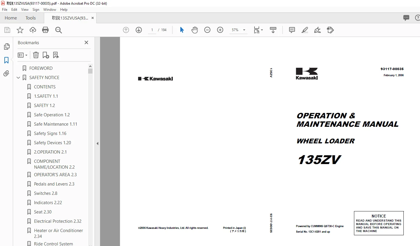
Kawasaki WHEEL DOZER 135ZV OPERATION & MAINTENANCE MANUAL 93117-00035 – PDF
$28.95
Kawasaki WHEEL DOZER 135ZV OPERATION & MAINTENANCE MANUAL 93117-00035 – PDF DOWNLOAD
Powered by CUMMINS QST30-C Engine
Serial No. 13C1-0201 and up
Description
Kawasaki WHEEL DOZER 135ZV OPERATION & MAINTENANCE MANUAL 93117-00035 – PDF DOWNLOAD
FILE DETAILS:
Kawasaki WHEEL DOZER 135ZV OPERATION & MAINTENANCE MANUAL 93117-00035 – PDF DOWNLOAD
Language :English
Pages :194
Downloadable : Yes
File Type : PDF
IMAGES PREVIEW OF THE MANUAL:
DESCRIPTION:
Kawasaki WHEEL DOZER 135ZV OPERATION & MAINTENANCE MANUAL 93117-00035 – PDF DOWNLOAD
Powered by CUMMINS QST30-C Engine
Serial No. 13C1-0201 and up
FOREWORD
- Congratulations on your purchase of the Kawasaki Wheel Loader 135ZV. This manual contains safety, operation, transportation, maintenance and troubleshooting information. Read and understand the information in this manual carefully before operating or performing any maintenance of the machine. Failure to do so could result in personal injury or equipment failure.
- The safety of yourself and others depends upon your care and judgement in the operation and maintenance of this machine. Keep the manual with this machine at all times. Kawasaki pursues a policy of continuing improvement in design and performance of this machine.
- The right is therefore reserved to vary specifications without prior notice or obligation. This machine gives you, our customer, the maximum in performance and durability, state of the art technology and safety. Should you have any question regarding this machine or manual, please contact the Kawasaki dealer in your area during regular business hours. A satisfied customer is our goal
- . For additional details, for safe and efficient operation and maintenance of your Cummins engine, please refer to your Cummins operation & maintenance manual. There may be an optional supplemental operation & maintenance manual, and this also should be referred to when operating machines that are equipped with special packages.
- This manual is compiled for persons who understand English. If an operator or maintenance person does not understand English, please translate what said in this manual into his mother language.
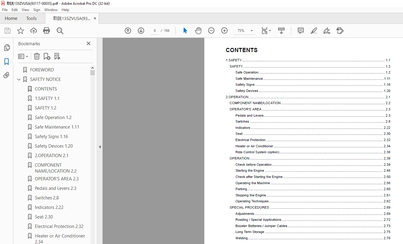
TABLE OF CONTENTS:
Kawasaki WHEEL DOZER 135ZV OPERATION & MAINTENANCE MANUAL 93117-00035 – PDF DOWNLOAD
Powered by CUMMINS QST30-C Engine
Serial No. 13C1-0201 and up
FOREWORD 4
SAFETY NOTICE 5
CONTENTS 6
1SAFETY 11 6
SAFETY 12 6
Safe Operation 12 6
Safe Maintenance 111 6
Safety Signs 116 6
Safety Devices 120 6
2OPERATION 21 6
COMPONENT NAME/LOCATION 22 6
OPERATOR’S AREA 23 6
Pedals and Levers 23 6
Switches 28 6
Indicators 222 6
Seat 230 6
Electrical Protection 232 6
Heater or Air Conditioner 234 6
Ride Control System (option) 238 6
OPERATION 239 6
Check before Operation 239 6
Starting the Engine 248 6
Check after Starting the Engine 250 6
Operating the Machine 256 6
Parking 260 6
Stopping the Engine 261 6
Operating Techniques 262 6
SPECIAL PROCEDURES 269 6
Adjustments 269 6
Roading / Special Applications 272 6
Booster Batteries / Jumper Cables 273 6
Long Term Storage 275 6
Welding 278 6
3MAINTENANCE 31 7
MAINTENANCE 32 7
Serial Number Location 32 7
Inspection and Maintenance Table 36 7
When Required Inspection and Maintenance 39 7
Every 10 Hours or Daily 318 7
Every 50 Hours or 1 Week 319 7
Every 250 Hours or 1 Month 325 7
Every 500 Hours or 3 Months 336 7
Every 1000 Hours or 6 Months 340 7
Every 2000 Hours or 1 Year 348 7
Recommended Lubricants 356 7
Coolant Specification 357 7
TROUBLESHOOTING 358 7
QUANTUM FAULT CODE INFORMATION FOR ENGINE 363 7
SPECIFICATIONS 368 7
Standard Specifications 368 7
High Lift Boom Specifications 370 7
1SAFETY 8
SAFETY 9
Safe Operation 9
Operator Safety 9
Mounting and Dismounting Safety 10
Before Starting Safety 11
Operational Safety 13
SITE SAFETY: 13
SAFETY DURING NORMAL OPERATIONS: 14
SPECIAL OPERATING CONDITIONS: 16
Parking Safety 17
Safe Maintenance 18
Safety Preparations Before Maintenance 18
Explosion / Fire / Burn Prevention 20
Other Maintenance Safety Concerns 21
Safety Signs 23
NOTE 23
Safety Devices 27
Loading Control Lever Lock 27
K-Lever Steering System On / Off 27
Articulation Stopper 28
To lock: 28
1 Align the front and rear chassis straight ahead 28
2 Remove the spring pin and pin to remove the articulation stopper from the storage bracket under the hydraulic oil tank 28
3 Turn the link and fix the end to the bracket on the front chassis (as shown) 28
4 Insert the pin and clip pin (This is the LOCKED position) 28
To unlock: 29
1 Remove the spring pin and pin from the end of the articulation stopper on the front chassis bracket 29
2 Turn the link to the rear chassis bracket 29
3 Insert the pin and clip pin (This is the STORED position) 29
Neutral Start System 29
Emergency Brake 29
Emergency Steering (option) 30
If the emergency steering works: 30
1 Keep the starter switch in the “ON” position even when the engine unexpectedly stops 30
2 Immediately operate the K-Lever to bring the machine to a road shoulder or safe location 30
3 Stop the machine If necessary, use the service brakes, emergency brake or lower the attachment to stop the machine 30
4 Place wheel chocks in front of and behind the tires to prevent the machine from moving 30
5 Contact your local Kawasaki dealer for necessary testing and repair 30
ROPS (Roll Over Protective Structure) 30
MEMO 31
2OPERATION 32
COMPONENT NAME/LOCATION 33
1 Bucket (Attachment) 33
2 Boom 33
3 “Z” Lever 33
4 Boom Cylinders 33
5 Bucket Cylinders 33
6 Engine 33
7 Torque Converter 33
8 Transmission 33
9 Radiator, Air Cooler & Hydraulic Oil Cooler 33
10 Torque Converter Oil Cooler 33
11 Fuel Tank (Right hand side) 33
12 Hydraulic Oil Tank (Left hand side) 33
13 Front Axle / Differential Ass’y 33
14 Rear Axle / Differential Ass’y 33
15 Air Cleaner 33
16 Parking Brake 33
17 1st Propeller Shaft 33
18 2nd Propeller Shaft 33
19 3rd Propeller Shaft 33
20 Batteries (two each side–two 12VDC=24VDC system) 33
21 Precleaner 33
22 Exhaust Mufflers 33
23 Steering Cylinders 33
24 ROPS 33
OPERATOR’S AREA 34
Pedals and Levers 34
1 K-Lever 34
2 Loading Control Lever 34
3 Accelerator Pedal 34
4 Brake Pedals 34
5 Wrist Rests (adjustable) 34
1 K-Lever 35
2 Loading Control Lever 35
Boom Control 36
(a) Float 36
(b) Lower 36
(c) Hold 36
(d) Raise 36
Bucket Control 36
(a) Dump 36
(b) Hold 36
(c) Roll Back 36
3 Accelerator Pedal 37
4 Brake Pedals 37
1 As a brake only pedal by turning the transmission cut-off (Declutch) switch (See page 213) to the “OFF” position Use this position when working on slopes or ramps 37
2 Disengage the transmission while applying the brakes This is normally used when loading trucks It allows higher engine spee 37
5 Wrist Rests (adjustable) 38
1 Loading control lever side 38
2 K-Lever side 38
Switches 39
1 Starter Switch 39
2 Parking Brake Switch 39
3 Light Switch 39
4 Front Working Light Switch 39
5 Rear Working Light Switch 39
6 Ladder Light Switch 39
7 Ladder Light Switch 39
8 Boom Soft Landing Switch 39
9 Engine Mode Switch 39
10 Transmission Cut-Off (Declutch) Switch 39
11 Traction Control Switch 39
12 Ride Control Switch (option) 39
13 Front Wiper Switch 39
14 Rear Wiper Switch 39
15 Diagnostic Switch (option) 39
16 Increment / Decrement Switch (option) 39
17 Power Boost Switch 39
18 QUAD (Quick Up And Downshift) Switch 39
19 Horn Switch 39
20 Forward / Reverse Changeover Switch 39
21 Transmission Shift Switch 39
22 Engine Stop Switch 39
23 Traction Control Engine Adjust Switch 39
24 Boom Soft Landing Height Adjust Switch 39
25 12 Volt Power-outlet Socket (S/N 0203~) 39
1 Starter Switch 40
2 Parking Brake Switch 40
3 Light Switch 41
4 Front Working Light Switch 41
5 Rear Working Light Switch 42
6 Ladder Light Switch 42
7 Ladder Light Switch 42
8 Boom Soft Landing Switch 43
9 Engine Mode Switch 43
10 Transmission Cut-Off (Declutch) Switch 44
OFF 44
ON 44
11 Traction Control Switch 44
12 Ride Control Switch (option) 45
13 Front Wiper Switch 45
14 Rear Wiper Switch 46
15 Diagnostic Switch (option) 46
16 Increment / Decrement Switch (option) 47
1 Checking the history of the engine failures 47
2 Adjusting the engine idle revolution 47
17 Power Boost Switch 48
18 QUAD (Quick Up And Downshift) Switch 49
19 Horn Switch 49
20 Forward / Reverse Changeover Switch 50
21 Transmission Shift Switch 50
22 Engine Stop Switch 51
23 Traction Control Engine Adjust Switch 51
24 Boom Soft Landing Height Adjust Switch 52
25 12 Volt Power-outlet Socket (S/N 0203~) 52
Indicators 53
1 Tachometer 53
2 Engine Coolant Temperature Gauge 53
3 Torque Converter Oil Temperature Gauge 53
4 Fuel Gauge 53
5 Parking Brake Indicator Lamp (red) 53
6 Auto Brake Indicator Lamp (red) 53
7 Transmission Cut-Off (Declutch) Lamp (green) 53
8 Working Light Indicator Lamp (green) 53
9 K-Lever Indicator Lamp 53
10 Central Warning Lamp (red) 53
11 Transmission Control Warning Lamp (red) 53
12 Brake Pressure Warning Lamp (red) 53
13 Brake Oil Temperature Warning and Brake Disk Wear Alarm Lamp (red) 53
14 Engine Oil Pressure Warning Lamp (red) 53
15 Engine Coolant Temperature Warning Lamp (red) 53
16 Torque Converter Oil Temperature Warning Lamp (red) 53
17 Air Cleaner Warning Lamp (red) 53
18 Charge Lamp (red) 53
19 Transmission Oil Filter Warning Lamp (red) 53
20 High Beam Indicator Lamp (blue) 53
21 Auto Shift Indicator Lamp (green) 53
22 Neutral Indicator Lamp (green) 53
23 Transmission Status Monitor 53
24 Hour Meter 53
25 Emergency Steering Warning Lamp (red) (option) 53
26 Engine Warning Lamps 53
27 Ride Control Indicator Lamp (green) (option) 53
28 Engine Grid Air Heater Lamp (yellow) (For cold start) 53
1 Tachometer 54
2 Engine Coolant Temperature Gauge 54
3 Torque Converter Oil Temperature Gauge 54
4 Fuel Gauge 54
5 Parking Brake Indicator Lamp (red) 55
6 Auto Brake Indicator Lamp (red) 55
7 Transmission Cut-Off (Declutch) Lamp (green) 55
8 Working Light Indicator Lamp (green) 55
9 K-Lever Indicator Lamp 55
10 Central Warning Lamp (red) 55
11 Transmission Control Warning Lamp (red) 56
12 Brake Pressure Warning Lamp (red) 56
13 Brake Oil Temperature Warning and Brake Disk Wear Alarm Lamp (red) 56
14 Engine Oil Pressure Warning Lamp (red) 56
15 Engine Coolant Temperature Warning Lamp (red) 57
16 Torque Converter Oil Temperature Warning Lamp (red) 57
17 Air Cleaner Warning Lamp (red) 57
18 Charge Lamp (red) 58
19 Transmission Oil Filter Warning Lamp (red) 58
20 High Beam Indicator Lamp (blue) 58
21 Auto Shift Indicator Lamp (green) 58
22 Neutral Indicator Lamp (green) 58
23 Transmission Status Monitor 58
24 Hour Meter 59
25 Emergency Steering Warning Lamp (red) (option) 59
26 Engine Warning Lamps 59
Engine stop lamp 59
Engine warning lamp 59
Engine protection lamp 59
27 Ride Control Indicator Lamp (green) (option) 60
28 Engine Grid Air Heater Lamp (yellow) (For cold start) 60
Seat 61
Seat Adjustment 61
Lumbar Support 61
Reclining 61
Seat Height 61
Air Suspension 61
Forward / Backward 61
Seat Belt 62
1 Fasten seat belt along your body without kinking or twisting it The seat belt buckle should firmly “snap” when coupled Keep buckle free of dirt and debris 62
2 For releasing the seat belt, push the red button where the belt attaches 62
Electrical Protection 63
Fuse Boxes 63
Fusible Link 64
1 If one of the fusible links is blown, the following symptom occurs 64
2 To check the cause and replace the fusible link, call your nearest Kawasaki dealer 64
Heater or Air Conditioner 65
(~October, 2005) 65
Ventilation Location and Mode 65
Switches 65
1 ON/OFF Switch 65
2 FAN ONLY Switch 65
3 TEMP UP/DOWN Switches (A) Temperature Display 65
4 FAN UP/DOWN Switches (B) Fan Speed Display 65
5 UPPER Mode Switch 65
6 LOWER Mode Switch 65
7 DEFROST Mode Switch 65
8 FAN ONLY Indicator LED 65
Operation of the Automatic Temperature Control unit 66
Front Panel Controls 66
1 ON/OFF Switch Turns the unit on and off 66
2 FAN ONLY Switch Switches the unit to the fan only mode and disables the Automatic Temperature Control 66
3 TEMP UP/DOWN Switches Allows the operator to adjust the temperature setpoint 66
4 FAN UP/DOWN Switches Allows the operator to adjust fan speed The “FAN ONLY” Indicator LED (8) will be turned on 66
5 UPPER Mode Switch Switches the unit into the upper air mode 66
6 LOWER Mode Switch Switches the unit into the lower air mode 66
7 DEFROST Mode Switch Switches the unit into the defog mode and routes the air to the defrost vents 66
NOTE 66
(November, 2005~) 67
Ventilation Location and Mode 67
Switches 67
Manual Heater Control 67
Manual Combo Control 67
1 Mode Control 67
2 Heat/AC Control 67
3 Temperature Control 67
4 Blower Control 67
Front Panel Controls 68
Blower Control 68
Temperature Control 68
Heat/AC Control 68
Mode Control 68
Ride Control System (option) 69
Operation and Function 69
1 Before travelling, turn the ride control system switch (1) ON The ride control system pilot lamp (2) turns ON 69
2 Move the machine forward The ride control system functions automatically when the machine travelling speed reaches more than 69
NOTE 69
OPERATION 70
Check before Operation 70
Walk-Around Inspection 70
Items to Check and What to Look for: 70
Check Engine Oil Level 71
1 Check the oil level with the dipstick 71
2 Keep the oil level between the “H” (high) mark and “L” (low) mark on the dipstick 71
3 If needed, add the required amount of the same brand and viscosity oil as originally used through the refill port Refer to “Recommended Lubricants” page 356 for the suitable viscosity of the oil according to the ambient temperature 71
4 If the oil is particularly dirty or contains water (milky appearance), replace the oil immediately If oil contains coolant, 71
NOTE 71
Check Hydraulic Oil Level 72
1 Lower the attachment to the ground 72
2 Stop the engine 72
3 Check the oil level gauge on the side of the hydraulic oil tank 72
4 The oil level is OK if the oil reaches the middle of the level gauge 72
5 If needed, add the required amount of the oil Refer to “Recommended Lubricants” page 356 72
Check Engine Coolant Level 73
1 Stop the engine and allow the radiator and coolant to cool completely 73
2 Check the coolant level by the sight gauge on the radiator through the hole on the left hand side of the engine room Coolant 73
3 Slowly open the cap of the radiator tank to release any remaining pressure 73
4 If needed, add the required amount of the coolant Refer to “Coolant Specification” page 357 for the correct mixture 73
5 Change the coolant if it is particularly dirty Refer to “Replace Coolant” page 315 74
6 If the coolant contains oil, diagnose the problem and correct it immediately 74
Drain Water and Sediment from Fuel Filters 74
Check Wiring Harnesses 75
Articulation Stopper 75
Check Tire for Damage, Deformation and Wear 76
ROPS (Roll Over Protective Structure) 77
Adjust and Check Rear View Mirrors 77
Check Parking Brake 77
Check Monitor Panel Operation 78
1 Turn the starter switch to the “ON” position 78
2 All warning lamps (red) should come on for about three seconds Refer to “Indicators” page 222 78
3 Operate the transmission shift switch to each position, turn on the light switch to high beam position, and operate the rear working light switch and transmission cut-off (Declutch) switch 78
4 The transmission status monitor lamps (green) and the indicator lamps (green or blue) should come on respectively 78
5 If any lamps do not light up, replace the bulbs Refer to “Indicators” page 222 78
Check Control Levers 78
Check K-Lever and Forward/Reverse Changeover Switch 78
Check Horn Operation 78
1 Push the horn button on the loading control lever 78
2 The horn should sound loudly 78
Greasing 78
1 Park the machine on level ground, apply the parking brake, lower the attachment to the ground, and stop the engine 78
2 Lubricate fittings on the following components Wipe and clean all fittings before greasing Lubricate until fresh grease is 78
Starting the Engine 79
Normal Start 79
1 Do not depress the accelerator pedal 79
2 Turn the starter switch key to “ON” position and leave it there for 3 seconds Check the indicator lamps 79
3 The turn the starter switch key to “START” position to “pre-lube” the engine Keep the key in the “START” position during the pumping 79
4 After several seconds delay, the starter motor will crank to start the engine To protect starter and battery, do not keep the starter switch in the “START” position with the engine cranking for more than 25 seconds 79
5 If the engine fails to start, wait about two minutes before trying to restart This allows the starter motor to cool which prevents starter motor damage 79
6 After the engine starts, release the key and it will return to the “ON” position automatically 79
7 If the forward/reverse changeover switch is not in the “NEUTRAL” position, the engine will not crank 79
NOTE 80
Cold Start 80
Check after Starting the Engine 81
Check Warning Lamps 81
1 Check the warning lamps on the instrument panel 81
2 If any red lamp (except for “PARKING”) is on, do not operate the machine 81
3 Refer to “Indicators” page 222 for the meaning of each lamp and the correction 81
Check Fuel Level 82
1 Check the fuel level with the fuel gauge indicator on the instrument panel 82
2 Add fuel to fill the tank if the gauge shows below “F” Refer to “Recommended Lubricants” page 356 for the proper fuel 82
Check Transmission Oil Level 82
1 Park the machine on level ground, apply the parking brake, and lower the attachment to the ground Verify that oil is up on the dipstick prior to starting 82
2 Set the articulation stopper in the “LOCKED” position Refer to “Articulation Stopper” page 121 82
3 Check the transmission oil level with engine at low idle 83
4 The oil level is OK if the oil reaches the middle of the level gauge 83
5 If the oil level is lower than the specified, add recommended oil through the oil inlet hole while the engine is at idle Do not overfill Refer to “Recommended Lubricants” page 356 83
Check Service Brake Operation 84
1 Turn “OFF” the clutch cut-off (Declutch) switch 84
2 Firmly depress the left brake pedal 84
3 Release the parking brake 84
4 Select the transmission changeover switch 1st and FORWARD 84
5 Slowly accelerate the engine to full speed 84
6 The machine should not move 84
Check Parking Brake Operation 84
1 If the service brakes work normally, test the parking brake 84
2 Move the machine to a safe open place on a grade 84
3 Stop the machine with the service brake 84
4 Pull up the parking brake switch 84
5 Release the service brakes 84
6 The machine should not move 84
Check Steering Wheel Operation 84
1 Be sure the area is clear of bystanders 84
2 Release the brakes 84
3 Steer fully right and then left 84
4 Steering should be smooth in both directions 84
Check Back-up Alarm Operation 85
1 Apply the service brakes 85
2 Release the parking brake 85
3 Set the forward/reverse changeover switch to “REVERSE” 85
4 The back-up alarm should sound and be heard in the operator’s seat 85
Check Exhaust Gas 85
1 Check the color of the exhaust gas Normal exhaust gas color is clear or light gray when engine is warm White, black, or blu 85
2 If abnormal exhaust gas color occurs, have the machine checked immediately Refer to “TROUBLESHOOTING” page 359 85
General Inspection 86
Operating the Machine 87
Starting the Machine 87
1 Raise the bucket to the carry position approximately 40cm (16in) above the ground 87
2 Depress the brake pedal 87
3 Push the parking brake switch to release the parking brake 87
4 Press the transmission shift switch to the desired travel speed mode and then shift to the desired direction 87
5 Release the brake pedal then depress the accelerator pedal to drive the machine 87
Starting the Machine on a Grade 88
1 Turn “OFF” the clutch cut-off (Declutch) switch 88
2 Depress the left brake pedal 88
3 Depress the accelerator pedal while releasing the left brake pedal to start the machine off slowly 88
Speed and Direction Change 88
1 Select the proper gear shifting mode by pressing the transmission shift switch Refer to the following tables on page 258 fo 88
2 For a direction change, decelerate the machine then setting forward / reverse changeover switch to forward or reverse 88
3 When the transmission is in the 2nd gear, it can be quickly shifted down to the 1st gear by pressing the Quick Up And Downshift (QUAD) switch 89
4 Pressing the QUAD switch again, setting the forward/reverse changeover switch to the neutral position (parallel) or operating 89
Shift up and shift down chart 89
Steering 90
Auto Brake 90
1 If the machine runs above the following speeds forward or reverse; 90
2 When the direction is changed while running over 12km/h (75mph) 90
Parking 91
1 Release the accelerator pedal 91
2 Apply the service brake to stop the machine 91
3 Shift the transmission shift to “NEUTRAL” 91
4 Pull up the parking brake switch to apply the parking brake 91
5 Lower the attachment to the ground and apply a small amount of down pressure 91
Stopping the Engine 92
1 Let the engine idle for about five minutes before stopping 92
2 Turn the starter switch to the “OFF” position to stop the engine 92
3 After stopping the engine, remove the key and store it in a safe place 92
Operating Techniques 93
Loading 93
NOTE 93
1 Move the machine forward to the material 93
2 Steer the machine in a straight ahead position when entering the material 93
3 Lower the bucket parallel to the ground 93
4 Drive the bucket straight into the material Use approximately 1/2 – full engine speed 94
5 Move the loading control lever to the “Raise” detent position and run the machine forward slowly in 1st or 2nd speed Reduce wheel slippage by slightly reducing engine speed 94
6 Move the loading control lever to the “Roll Back” and the “Hold” position several times to get more material in the bucket 94
7 When the bucket is filled, move the loading control lever to the “Roll Back” position 94
8 Release the loading control lever to the “Hold” position and the boom will rise 94
9 Reverse the machine 94
10 On later passes, aim the center of the bucket at the protruding portion of the material 94
Excavating 95
1 Move the machine forward to the material 95
2 Steer the machine in a straight ahead position when entering the material 95
3 Lower the bucket parallel to the ground or dump it slightly forward 95
4 Run the machine slowly in 1st or 2nd speed Increase engine speed as the bucket digs deeper 95
5 When the bucket is filled, move the loading control lever to the “Roll Back” position 95
6 Move the loading control lever to the “Raise” position to clear the ground 95
Dozing 95
Ground Levelling 96
1 Keep the loaded bucket slightly above the ground 96
2 While running the machine backward, dump the bucket little by little to evenly spread material on the ground 96
3 Dump the bucket, allow the cutting edge to contact the ground, and run the machine backward 96
4 To get smoother surface, put some material in the bucket, place the bucket parallel to the ground, run the machine backward with the loading control lever in the “Float” position 96
Carrying 97
1 Fully roll back the loaded bucket before carrying to prevent spillage 97
2 Keep the bucket approximately 40cm (16in) above the ground when carrying 97
Dumping into Truck or Hopper 97
1 Move the loading control lever to the “Raise” position to raise the loaded bucket while approaching the truck or the hopper 97
2 Use the transmission cut-off (Declutch) switch in the “ON” position if working on a level site When the left brake pedal (Declutch pedal) is depressed, the transmission is placed automatically in neutral and the boom rises faster 97
3 Return the loading control lever to the “Hold” position when the bucket reaches the enough height to clear the truck or hoppe 98
4 Position the machine in the center of the truck body or hopper to dump the load 98
5 Move the loading control lever right to the “Dump” position to empty the bucket 98
6 Roll back the bucket to clear the truck or hopper sideboards and lower the boom while reversing the machine 98
Typical Truck Loading Methods 99
I Cycle Operation 99
V or L Cycle Operation 99
T Cycle Operation 99
SPECIAL PROCEDURES100
Adjustments100
Bucket / Attachment Positioner Adjustment100
1 Park the machine on level ground and apply the parking brake100
2 Lower the attachment to the ground, adjust it to the desired angle, set the bucket control lever to the hold position, and stop the engine100
3 Loosen the bolts (1) with a 17mm wrench100
4 Move the bracket (2) forward to increase, or rearward to decrease the attachment preset angle100
5 Tighten the bolts (1)100
6 To test the adjustment; start the engine, raise the boom approximately half way, dump the attachment, and move the loading co100
NOTE100
Boom Kickout Adjustment101
1 Park the machine on level ground and apply the parking brake101
2 Raise the boom to the desired height and stop the engine101
3 Lock the loading control lever in the “Hold” position using the loading control lever lock101
4 Block the boom and linkage from falling down using a proper support101
5 Loosen the two bolts (1)101
6 Move the plate (2) clockwise to decrease, or counterclockwise to increase the boom lift kickout height101
7 Tighten the bolts (1)101
8 Remove the support from the boom and linkage101
9 To test the adjustment; start the engine, slowly lower the boom to the ground, and move the loading control lever to the “Rai101
NOTE101
Boom Soft Landing Adjustment102
1 Park the machine on level ground and apply the parking brake102
2 Raise the boom to the desired height and stop the engine102
3 Lock the loading control lever in the “Hold” position using the loading control lever lock102
4 Block the boom and linkage from falling down using a proper support102
5 Loosen the two bolts (1)102
6 Move the plate (2) clockwise to decrease, or counterclockwise to increase the boom soft landing height102
7 Tighten the bolts (1)102
8 Remove the support from the boom and linkage102
9 To test the adjustment; start the engine, turn the boom soft landing switch to “ON”, lift the boom, and move the loading cont102
NOTE102
Roading / Special Applications103
Booster Batteries / Jumper Cables104
NOTE104
1 Before connecting jumper cables:104
2 Raise and lock the battery box covers104
3 Be sure vent caps are tight and level Place damp cloth over vent caps on both batteries104
4 Move back the protective rubber covers (red) from the positive post (+) of the battery104
5 Connect one end of the red jumper cable to the positive post (+) of the discharged battery104
6 Connect the other end of the red jumper cable to the 24 volt side of the booster battery set or power source104
7 Connect one end of the black jumper cable to the ground side of the booster battery set or power source104
8 The final connection should be the remaining end of the black jumper cable to the rear chassis close to starter motor ground being jump started104
9 Start the booster machine’s engine or turn the auxiliary power source on104
10 Allow a few minutes to provide partial charge to the discharged batteries104
11 Start the machine being boosted as described on “Starting the Engine” page 248105
12 As soon as the engine starts, disconnect the jumper cables in the reverse order (Step 8, Step 7, Step 6, Step 5)105
13 Remove the damp cloth and replace the protective covers over the battery terminals and close the battery box covers105
14 Test the starting / charging system to determine the cause of the problem and correct it105
Long Term Storage106
Before Storage106
1 Wash and clean all parts of the machine106
2 Lubricate every greasing point described in “Greasing” section page 319 and 354106
3 Replace engine oil, transmission oil, differential and planetary oil, and hydraulic system oil106
4 Idle the engine for about 15 minutes so that fuel and lubricant circulate throughout the engine, transmission and torque converter106
5 Store the machine indoors and keep it dry Never leave it outdoors If forced to leave it outdoors, choose a flat place, place the machine on wooden blocks and securely cover it with a canvas or plastic cover, etc106
6 Disconnect the cables from the batteries or if freezing temperatures are expected, remove the batteries from the machine and store separately in a heated area106
7 If freezing temperatures are expected, check and adjust the antifreeze/water mixture Refer to “Coolant Specification” page 357 for the mixing ratio106
8 Securely cover the inlet and outlet ports of the air cleaner and muffler106
During Storage106
1 Check the following points Refer to “Check before Operation” page 239 and “Check after Starting the Engine” page 250106
2 Operate the machine as follows106
3 Operate the air conditioner as follows106
After Storage107
1 Loosen the drain cock or plug of the fuel tank and the hydraulic oil tank to drain any water into a suitable container Dispose of properly107
2 Remove the covers, connect the cables to the batteries and start the engine107
3 Replace engine and transmission oil with new specified oil after warming up both engine and transmission Refer to “Replace Engine Oil Filter Cartridges” page 325 and “Replace Transmission Oil” page 340107
4 Start the engine and check for any abnormalities107
5 Warm up the machine until all gauges reach the normal range107
Cautions on Battery Replacement or Battery Cable Removal107
1 Turn the starter switch key to ON position107
2 Slowly depress the accelerator pedal to the full stroke position 3 times (Keep it at the full stroke position 2 seconds and release it)107
3 Turn the starter switch key to OFF position108
4 Start the engine and check the max engine speed108
Welding109
Cautions Regarding Welding Repair Service109
1 Turn the starter switch OFF109
2 Leave the machine as it is more than 1 minute109
3 Remove the battery terminals both positive and negative sides from the battery109
4 The controller circuit breaker should be turned “OFF” 109
5 Ground the welder near the section to be welded109
6 To ground the welder, check that the electric current will not flow through the cylinders Cylinder head covers for some models have a low-conductive metal that will cause spark if the welding current flows The spark may damage the cylinder rod109
7 The weld spattered on the hydraulic cylinders and on the plated sections of pins will damage the cylinders and pins There ar109
NOTE109
MEMO111
3MAINTENANCE112
MAINTENANCE113
Serial Number Location113
1 Machine Serial Number113
2 Engine Serial Number113
3 Transmission Serial Number Model Serial Number Design Number113
4 Torque Converter Serial Number Model TC650A01 Serial Number114
5 Bucket or Attachment Serial Number114
6 ROPS Serial Number ROPS: Model Number Serial Number114
7 CAB Serial Number114
8 Seat Serial Number115
9 Air Conditioner and Heater Serial Number115
Inspection and Maintenance Table117
△: First time replacement or cleaning only117
△: First time replacement or cleaning only118
△: First time replacement or cleaning only119
When Required Inspection and Maintenance120
Replace Bucket Teeth120
1 Park the machine on level ground and apply the parking brake120
2 Raise the bucket to a convenient height and put blocks under the bucket to prevent it from coming down120
3 Stop the engine120
4 Remove the pin and tooth using a tool120
5 Install the tooth onto the tooth adapter121
6 Install the pin with the guide rib facing back121
7 Tap the pin in flush ear using 2 to 4 pound hammer (1 ~ 2kg)121
NOTE121
Check and/or Replace Seat Belt121
1 Inspect the condition of the seat belt and all mounting hardware frequently121
2 Replace the seat belt or any part of the mounting hardware if it is damaged121
3 Replace the seat belt every three years regardless of its condition or appearance121
Clean or Replace Air Cleaner Element122
1 Park the machine on level ground, apply the parking brake, lower the attachment to the ground, and stop the engine122
2 Remove the cover (2) by loosening wing nut (1)122
3 Remove the outer element122
4 If the element is clogged by dirt or dust, spray dry compressed air (196kPa (30psi)) along the inside of the element up and down to blow off dust Do not breathe the dust If necessary wear a protective mask122
5 Insert a lamp inside of the element for checking a damaged element122
6 If bright light spots are seen through the element, there are cracks or pinholes in the element Replace it with a new element122
7 Inspect the rubber seal (3) If there is any damage to the seal, replace the element122
8 Confirm that the wing nut is tight and the inner element is properly seated, then reinstall the outer element, cover (2) and wing nut (1)122
9 Even after cleaning, if the engine exhaust gas is not clean enough (excessive black smoke), replace the element122
10 After six cleanings or once a year replace the outer element together with the inner element122
Clean Radiator/Air cooler/Hydraulic oil cooler Fins123
1 Park the machine on level ground, apply the parking brake, lower the attachment to the ground, and stop the engine123
3 Blow off mud, dirt, or clogging debris from the radiator / air cooler / hydraulic oil cooler fins with compressed air Use a pressure washer to remove harder debris Compressed air or water should be directed from rear toward the engine123
4 Reverse the direction to flush all debris from the radiator / air cooler / fuel cooler fins123
NOTE123
Check or Replace Fuses124
1 Park the machine on level ground, apply the parking brake, and lower the attachment to the ground124
2 Stop the engine and turn the starter switch key to the “OFF” position124
3 Open the covers of the main fuse box and cab fuse box124
4 Check the fuses If any blown fuses are found, replace them with new ones Refer to “Fuse Boxes” page 232124
5 Determine the cause of the blown fuses and repair124
Check Windshield Washer Fluid124
1 Park the machine on level ground, apply the parking brake, and lower the attachment to the ground124
2 Check the fluid level124
3 Replace the fluid if it is dirty124
4 If the level is low, add fluid to proper level124
5 Use windshield washer solvent for both better cleaning and to prevent freezing Adjust the mixture according to the manufacturer’s instructions124
Clean Air Conditioner Condenser125
1 Park the machine on level ground, apply the parking brake, lower the attachment to the ground, and stop the engine125
2 Inspect the condenser and replace it if any damage is found125
3 Clean its fins using compressed air, a pressure washer or a soft brush Be sure the air pressure is below 196kPa (30psi) If a pressure washer is used, keep the nozzle about 50cm (20in) away from the fins to prevent fin damage125
4 If water is used for the cleaning, cover the electrical parts of the engine and the electric condenser fans with plastic sheets Remove the plastic sheets after cleaning125
Replace Air Conditioner Filter Elements125
Outer filter replacement125
1 Park the machine on level ground, apply the parking brake and lower the attachment to the ground125
2 Turn the air conditioner “OFF” and stop the engine125
3 The cover for the outer filter is located at the right rear side of the cab Turn the rings counterclockwise and then remove the cover125
4 Remove the outer filter from the cab, and replace it with new one (Part number 40330- 60270) When installing the outer filter into the cab, be sure to align the air flow arrow on the outer filter to point toward the cab125
5 Install the cover to the cab and turn the rings clockwise to fix the cover126
Inner filter replacement126
1 The inner filter is located at the right behind the operator’s seat Unscrew the turn knob to remove the filter cover Remove the filter and replace with a new one (Part number 40332-70100)126
Replace Coolant126
1 Park the machine on level ground, apply the parking brake, lower the attachment to the ground, and stop the engine126
2 Inspect all coolant hoses Replace any that are cracked, swollen, or brittle126
3 Slowly open the radiator cap (1) to release any remaining pressure126
4 Remove the cap (1) slowly126
5 Open the drain cocks (2), (3) and drain coolant about 270liters (713gal) into a suitable container Do not remove the coolant filter127
6 Follow local regulations to properly dispose of or recycle the coolant127
7 Close the drain cocks and fill the cooling system with clean water and cooling system cleaner Follow the manufacturer’s instructions Do not install the radiator cap127
8 Operate the engine for one hour with the coolant temperature above 80ºC (180ºF) Then let the engine cool down naturally with the engine shut “OFF”127
9 Stop the engine and open the drain cocks to drain the cooling system127
10 Close the drain cocks and fill the cooling system with clean water Do not install the radiator cap or the new coolant filter127
11 Operate the engine for five minutes with the coolant temperature above 80ºC (180ºF)127
12 Stop the engine and open the drain cocks to drain the cooling system127
13 If the water being drained is still dirty, the system must be flushed again until the water is clean (step 7 ~ 13)127
14 Close the drain cocks and fill the system with the premixed coolant Refer to “Coolant Specification” page 357 for the mixing instruction127
15 Add seven units of DCA65L coolant additive at the same time127
16 Replace the DCA4 coolant filter (WF2075) Refer to “Replace DCA4 Coolant Filter Cartridges” page 328 for the procedure127
17 Idle the engine for five minutes to purge air mixed into the coolant (Leave the radiator cap off)127
18 Add coolant as necessary127
19 Reinstall the radiator cap127
Replace Air Conditioner Receiver Dryer128
Every 10 Hours or Daily129
Every 50 Hours or 1 Week130
Greasing130
1 Park the machine on level ground, apply the parking brake, lower the attachment to the ground, and stop the engine130
2 Lubricate fittings on the following components Wipe and clean all fittings before greasing Lubricate until fresh grease is 130
Drain Water and Sediment from Fuel Tank132
1 Park the machine on level ground, apply the parking brake, lower the attachment to the ground, and stop the engine132
2 Prepare a suitable container132
3 Open the drain cock on the bottom of the fuel tank132
4 Drain water and sediment along with fuel132
5 Close the drain cock132
6 Properly dispose of the drained fuel and water132
7 Add fuel132
NOTE132
Check Battery Electrolyte Level133
1 Park the machine on level ground, apply the parking brake, lower the attachment to the ground, and stop the engine133
2 Clean the battery surface with a clean cloth or soft brush133
3 Check the battery electrolyte level in each cell Electrolyte should cover the cell plates133
4 If the level is low, add distilled water until it reaches the bottom of the filler neck133
NOTE133
Check Tire Air Pressure134
1 Before starting work and while the tires are still cool, measure the tire air pressure with the tire pressure gauge134
2 Adjust air pressure according to the recommended pressures below When inflating a tire, stand behind the tread and use a self-attaching chuck with a remotely located valve to turn air pressure on and off134
Every 250 Hours or 1 Month136
Replace Engine Oil Filter Cartridges136
1 If the machine is cold operate the engine to bring the engine coolant temperature about 60ºC (140ºF) When the needle of the coolant temperature gauge reaches the middle of the white zone, the temperature is about 60ºC (140ºF)136
2 Park the machine on level ground, apply the parking brake, lower the attachment to the ground, and stop the engine136
3 Place a container under the filters to catch any spilled engine oil Remove the oil filters using an oil filter wrench and properly dispose of them Make sure the O-ring is removed with the filter136
4 Clean the oil filter head gasket surface136
5 Fill the new filters with clean engine oil Refer to “Recommended Lubricants” page 356 for the oil specifications136
6 Apply a light film of engine oil to the gasket surface of the new filter cartridge (full-flow and bypass oil filters)136
7 Install and tighten the filter until the gasket contacts filter head surface Then tighten it by hand an additional three-fourths to one (3/4 to 1) turn Refer to the instructions supplied with the filter137
8 Idle the engine to inspect for leaks at the filter137
9 Stop the engine Wait approximately five minutes to let the oil drain back to the oil pan137
10 Check the oil level137
11 Add the specified oil if necessary to bring the oil level to the “H” (High) mark on the dipstick137
12 Properly dispose of the filters137
Replace Fuel Filters138
1 Park the machine on level ground, apply the parking brake, lower the attachment to the ground, and stop the engine138
2 Place a small drain pan (about 1liter (1qt)) under the fuel filters138
3 Remove and properly dispose of the fuel filters138
4 Clean the filter head gasket surface138
5 Apply a light film of clean engine oil to the gasket surface of the new filters138
6 Fill the filters with clean fuel138
7 Install the filter on the filter head Turn it until the gasket contacts the filter head surface138
8 Tighten the filter an additional one-half to three-fourths turn after the gasket contacts the filter head surface Follow the instructions supplied with the filter138
Replace DCA4 Coolant Filter Cartridges139
1 Park the machine on level ground, apply the parking brake, lower the attachment to the ground, and stop the engine139
2 Slowly open the radiator cap to release any remaining pressure, and remove the cap slowly139
3 Turn the coolant shut-off valves (2)139
4 Remove and properly dispose of the coolant filters (1)139
5 Clean the filter head gasket surface139
6 Apply a light film of clean engine oil to the gasket surface of a new DCA4 coolant filter cartridges (WF2075)139
7 Install the filter firmly by hand Follow the instructions supplied with the filter139
8 Open the coolant shut-off valve and install the radiator cap139
9 Run the engine and check for coolant leaks139
10 Idle the engine for about five minutes to purge all the air from the coolant139
11 After air has been purged from the system, stop the engine and check the coolant level again139
12 If needed, add required amount of the coolant Refer to “Coolant Specification” page 357 for the correct mixture140
Clean Crankcase Breather Tube140
Check and Adjust Belt Tension141
Inspection141
1 Park the machine on level ground, apply the parking brake, lower the attachment to the ground, and stop the engine Remove the key and place “Do Not Operate” tag on the instrument panel141
2 Open the engine side panel141
3 Visually inspect the fan belt for looseness and damage141
4 If the belt is too stretched to permit adjustment or shows cuts or cracks, replace it and adjust the tension correctly If multiple belts are used as a set, replace all of them141
5 Apply pressure approximately 98N (22lb) to the center of the belt between the pulleys; deflection of about 10mm (039in) is normal141
Adjustment141
1 Loosen the bolts (1) (2) (3) and lock nut (4) (5)141
2 Turn the adjusting link (6) to adjust the belt tension correctly141
3 Tighten the bolts and nuts141
Check Air Intake System142
1 Park the machine on level ground, apply the parking brake, lower the attachment to the ground, and stop the engine142
2 Check the engine intake hose, intake pipes, pipe clamps and hose bands for damage and tightness142
3 If damaged or loose, replace or retighten or contact your nearest Kawasaki dealer142
Check Differential Gear Oil142
1 Park the machine on level ground, apply the parking brake, lower the attachment to the ground, and stop the engine142
2 Remove the oil level plug from the front axle housing, using a 12mm hex (Allen) wrench142
3 If the oil level is lower than the plug, add the specified oil through the level plug hole Refer to “Recommended Lubricants” page 356142
4 If there is any sign of water in the oil, drain and replace the oil Oil containing water looks milky Dispose of the drained oil properly142
5 Install and tighten the level plug142
6 Check the rear axle oil level following the same steps142
Check Planetary Gear Oil143
1 Check the oil level on all four wheels143
2 Move the machine on level ground so that “TOP” mark (1) on the planetary gear housing comes top143
3 Turn “ON” the parking brake switch, lower the attachment to the ground, and stop the engine143
4 Remove the oil level plug (2) on the housing, using a 12mm hex (Allen) wrench143
5 If the oil level is lower than the plug, add the specified oil through the level plug hole Refer to “Recommended Lubricants” page 356143
6 Magnetic plugs are used for the planetary gear housing Wipe off the small amount of fine metallic powder that normally sticks to the plugs If abnormal debris is found, determine the cause and correct it143
7 If there is any sign of water in the oil, drain and replace the oil Oil containing water looks milky Dispose of the drained oil properly143
8 Install and tighten the level plug143
Check Tightness of Wheel Bolts143
1 Park the machine on level ground, apply the parking brake, lower the attachment to the ground, and stop the engine143
2 Check the wheel bolts are tightened to 892N-m (658ft-lb)143
3 Retighten if necessary143
Check and Adjust Air Conditioner Belt144
1 Park the machine on level ground, apply the parking brake, lower the attachment to the ground, and stop the engine Remove the key and page “Do Not Start” tag on the instrument panel144
2 Open the engine side panel144
3 Visually inspect the compressor belt on both top and bottom sides for looseness and damage144
4 If the belt is too stretched to permit adjustment or shows cuts or cracks, replace it and adjust the tension correctly144
5 Measure the belt tension using a belt tension gauge so that it is applied 540 ~ 735N (121 ~ 165lb)144
6 If the belt is too loose or tight, adjust the tension by loosening the four lock bolts (1) and turning the adjusting nut (2) on the compressor bracket144
7 Tighten the lock bolts (1)144
Clean Air Conditioner and Heater Filter Element145
Outer filter cleaning145
1 Park the machine on level ground, apply the parking brake, lower the attachment to the ground145
2 Turn the air conditioner “OFF” and stop the engine145
3 The cover for the outer filter is located at the right rear side of the cab Turn the rings counterclockwise and then remove the cover145
4 Remove the outer filter from the cab145
5 Remove dust with compressed air Use air pressure below 196kPa (30psi)145
6 To remove more stubborn debris, wash the filter with clean water Leave them for five to seven days to dry out of direct sunlight145
7 After approximately 8~10 cleanings, replace the filter with new one (Part number 40330- 60270) Refer to “Replace Air Conditioner Filter Elements” page 314145
8 When installing the outer filter into the cab, be sure to align the air flow arrow on the outer filter to point toward the cab145
9 Install the cover to the cab and turn the rings clockwise to fix the cover145
Inner filter cleaning145
1 The inner filter is located at the right behind the operator’s seat Unscrew the turn knob to remove the filter cover Remove the filter and clean145
2 Remove dust with compressed air Use air pressure below 196kPa (28psi)146
3 After approximately 8~10 cleanings, replace the filters with new one (Part number 40332- 70100) Refer to “Replace Air Conditioner Filter Elements” page 314146
4 Install the filter elements, install the filter cover146
NOTE146
Replace Filter146
Every 500 Hours or 3 Months147
Replace Transmission Oil Filter Elements147
1 If the machine is cold, operate the machine to bring the torque converter oil temperature about 30 to 40ºC (85 to 105ºF)147
2 Park the machine on level ground, turn “ON” the parking brake switch, lower the attachment to the ground, and stop the engine147
3 Place a suitable container (about 15liters (4gal)) under the transmission oil filters147
4 Remove the drain plugs from the bottom of the filter cases with 24mm wrench147
5 Remove the filter cases with 46mm wrench147
6 Replace the elements with new ones147
7 Replace the seals with new ones147
8 Clean the cases with solvent147
9 Clean the filter head gasket surface147
10 Apply a light film of clean engine oil to the seals surface of the new filters147
11 Reinstall the filters on the filter head147
12 Clean and install the oil drain plugs147
13 Idle the engine about ten minutes and inspect for leaks around the filters148
14 Check transmission oil level Refer to “Check Transmission Oil Level” page 251 Add the specified oil as necessary to bring the oil level to the middle of the level gauge Refer to “Recommended Lubricants” page 356 for the specified oil148
Replace Engine Oil148
1 If the machine is cold operate the engine to bring the engine coolant temperature to about 60ºC (140ºF) When the needle of the coolant temperature gauge reaches the middle of the white zone, the temperature is about 60ºC (140ºF)148
2 Park the machine on a level ground, apply the parking brake, lower the attachment to the ground, and stop the engine148
3 Remove the drain plug from the drain port148
4 Drain oil, about 133liters (351gal), into a suitable container148
5 Clean and install the oil drain plug, and tighten to 80N-m (60ft-lbs) torque148
6 Fill the engine with clean oil to the proper level149
7 Idle the engine to inspect for leaks at the drain plug149
8 Stop the engine Wait approximately five minutes to let the oil drain back to the oil pan149
9 Check the oil level again149
10 Add the specified oil if necessary to bring the oil level to the “H” (High) mark on the dipstick149
11 Properly dispose of or recycle the waste oil149
Clean Fuel Prefilter149
1 Park the machine on level ground, apply the parking brake, lower the attachment to the ground, and stop the engine149
2 Shut off valves to fuel tank149
3 Place a small drain pan (about 1 liter (1 qt)) under the fuel prefilter (1)149
4 Loosen the adapter (2) Remove the hose and remove the fuel prefilter (1)149
5 Clean the fuel prefilter (1) by washing oil149
6 Install the fuel prefilter (1) in the original place Install the hose150
7 Open valves at fuel tank150
Every 1000 Hours or 6 Months151
Replace Transmission Oil151
1 If the machine is cold operate the machine for a few minutes to bring the transmission oil temperature about 30 to 40ºC (85 to 105ºF)151
2 Park the machine on level ground, turn “ON” the parking brake switch, lower the attachment to the ground, and stop the engine151
3 Loosen the drain plug (1) with a 41mm wrench151
4 Drain oil into a suitable container (about 200liters (528gal)) Properly dispose of or recycle the waste oil151
5 Loosen the eight bolts (2) with a 17mm wrench152
6 Remove the flange (3) together with the pipe and suction strainer152
7 Remove the set screw from the strainer Remove the suction strainer from the flange Brush off any debris and clean with solv152
8 Remove the magnet plate from the transmission bottom side, then clean it After cleaning, put the magnet plate in the transmission bottom side152
9 Reassemble the strainer and flange assembly152
10 Tighten the drain plug and reinstall the strainer with a new gasket152
11 Tighten the eight bolts (2) to 937N-m (69ft-lb)152
12 Fill with the specified oil Refer to “Recommended Lubricants” page 356152
13 Idle the engine and check for leaks152
14 Check the oil level gauge Add the specified oil if necessary to maintain the proper oil level Refer to “Check Transmission Oil Level” page 251 and “Recommended Lubricants” page 356152
Check and Replace Transmission and Torque Converter Breather Element153
1 Park the machine on level ground, apply the parking brake, lower the attachment to the ground, and stop the engine153
2 Remove the breather for the transmission case and torque converter case 2pcs on the transmission case 2pcs on the chassis left side153
3 Clean the breather in the cleaning oil tub, then spray dry compressed air from the bottom of the breather Even after cleaning, if the breather is not clean enough, replace the breather153
4 Install the breather onto the transmission case and torque converter case153
Replace Hydraulic Oil Return Filter153
1 Park the machine on level ground, apply the parking brake, lower the attachment to the ground, and stop the engine153
2 Open the access cover on the left deck153
3 Press down the filler cap (1) to relieve the tank pressure153
4 Clean around the top of the filter cover (2)153
5 Remove four bolts (3) with a 17mm wrench and open the filter cover (2) The four bolts (3) may be used as “Jacking screws” to push up the cover Install them into the two threaded holes in the cover Screw them in equally to force the cover up evenly153
6 Remove the O-ring (4), spring (5), and bypass valve (6) from the filter housing154
7 Remove and properly dispose of the filter (7) and waste oil154
8 Clean the inside of the filter housing154
9 Replace the element (7) and O-ring (4)154
10 Apply a light film of clean hydraulic oil on the filter cover O-ring surface154
11 Install the new filter element (7), bypass valve (6), spring (5), new O-ring (4) and filter cover (2)154
12 Close the access cover154
Check Air Conditioner Refrigerant154
1 Apply the parking brake and lower the attachment to the ground154
2 Remove the cap154
3 Press the “FUN UP Arrow Switch” to set maximum air flow154
4 Set the temperature control switch fully to the cool position and fully open the cab doors154
5 Slightly accelerate the engine to about the middle speed range (compressor speed 1500 ~ 1800min-1 (RPM))154
6 Compare the flow of bubbles in the sight glass of the receiver drier with the drawings in the following table The new receiver drier also has moisture sensor window with color code to indicate moisture in the system154
Check Engine Compression Pressure155
Check Injection Pressure155
Check and Adjust Injection Timing155
Replace Transmission Oil Filter156
1 If the machine is cold, operate the machine to bring the torque converter oil temperature about 30 to 40ºC (85 to 105ºF)156
2 Park the machine on level ground, turn “ON” the parking brake switch, lower the attachment to the ground, and stop the engine156
3 Place a suitable container (about 4liters (1gal)) under the transmission oil filters156
4 Remove and properly dispose of the oil and filter156
5 Clean the filter head gasket surface156
6 Apply a light film of clean engine oil to the gasket surface of the new filter156
7 Install the filter on the filter head Follow the instructions on the filter156
8 Idle the engine about ten minutes and inspect for leaks around the filter156
9 Check transmission oil level Refer to “Check Transmission Oil Level” page 251 If needed, add the required amount of the oil Refer to “Recommended Lubricants” page 356 for the specified oil156
Greasing157
1 Park the machine on level ground, apply the parking brake, lower the attachment to the ground, and stop the engine157
2 Lubricate fittings on the following components Before lubricating the seal with grease, remove the breather nipple (A) Lubr157
Replace Filter in the Oil Tank Cap158
1 Park the machine on level ground, apply the parking brake, lower the attachment to the ground, and stop the engine158
2 Move the loading control lever back and forth to relieve the pressure158
3 Insert the key into the side of the filter cap (1) and turn the key counterclockwise158
4 Press down the filter cap (1) to relieve the tank pressure158
5 Remove the filter cap158
6 Remove spiral snap ring (2), valve assy (3), spring (4), filter element (5)158
7 Replace element (5) (Part number 30981- 70330)158
8 Install the element, spring, valve assy, and spiral snap ring158
Every 2000 Hours or 1 Year159
Replace Hydraulic Oil159
1 Park the machine on level ground, apply the parking brake, lower the attachment to the ground, and stop the engine159
2 Move the loading control levers back and forth to relieve the pressure159
3 Insert the key into the side of the filler cap (1) and turn the key counterclockwise159
4 Press down the filler cap (1) to relieve the tank pressure159
5 Remove the filler cap (1)159
6 Prepare a suitable container to catch the draining oil (about 310liters (819gal))159
7 Loosen the drain plug (2) with a 24mm wrench to drain oil160
8 Dispose of the waste oil properly160
9 Remove the nuts with a 14mm wrench to remove the inspection cover (3)160
10 Remove the set bolts in the suction strainers using a 8mm wrench Remove the suction strainers Inspect and clean them with 160
11 Clean inside of the tank and magnet plug (4)160
12 Install the suction strainers, new gasket (Part number 31990-25910) and inspection cover (3), and tighten the nuts evenly Do not overtighten160
13 Tighten the drain plug (2)160
14 Add the specified hydraulic oil through the oil inlet hole Refer to “Recommended Lubricants” page 356160
15 Close the oil filler cap (1)160
16 Start the engine and allow the engine to idle for about five minutes160
17 Operate the bucket, boom, and steering cylinders for about five minutes, then lower the attachment to the ground160
18 Inspect for leaks160
19 Make sure hydraulic oil is to the center of the oil level gauge Add hydraulic oil if necessary160
Replace Differential Gear Oil161
1 If the machine is cold operate the machine for a few minutes to bring the differential gear oil temperature about 40ºC (105ºF)161
2 Park the machine on level ground, apply the parking brake, lower the attachment to the ground, and stop the engine161
3 Remove the level plug (1) and drain plug (2) from the front axle housing, with a 12mm Hex (Allen) wrench Some fine metallic powder will normally stick to the magnet plug Simply wipe it off161
4 Drain the oil (about 220liters (58gal)) into a suitable container161
5 Dispose of the waste oil properly161
6 Install the drain plug161
7 Refill the recommended oil through the level plug hole (1) until the oil comes out from the hole Refer to “Recommended Lubricants” page 356161
8 Install and tighten the level plug161
9 Replace the rear differential oil following the same steps161
Replace Planetary Gear Oil162
1 Replace the planetary gear oil on all four wheels162
2 Move the machine on level ground so that “TOP” mark (1) on the planetary gear housing comes to the top162
3 Turn “ON” the parking brake switch, lower the attachment to the ground, and stop the engine162
4 Remove the level plug (2) and drain plug (3) from the planetary gear housing, using a 12mm hex (Allen) wrench Some fine metallic powder will normally stick to the magnet plug (2) Simply wipe it off162
5 Remove the drain plug (4) from the brake housing162
6 Drain the oil (about 50liters (13gal)) into a suitable container162
7 Dispose of the waste oil properly162
8 Install and tighten the drain plugs162
9 Refill the recommended oil through the level plug hole (2) until the oil comes out from the hole Refer to “Recommended Lubricants” page 356162
10 Install and tighten the level plug162
11 Repeat these steps for all four planetaries162
Check Vibration Damper163
1 Park the machine on level ground, apply the parking brake, lower the attachment to the ground, and stop the engine163
2 Check the damper on the fan end of the engine crankshaft163
3 If dents, cracks, mounting bolt looseness, or any deformations are found, contact your nearest Kawasaki dealer or Cummins Engine dealer for replacement163
Check Brake Accumulators163
1 Park the machine on level ground, apply the parking brake, and lower the attachment to the ground163
2 Run the engine at low idle for five minutes to fill the brake accumulators with oil163
3 Stop the engine163
4 Turn the key switch to the “ON” position163
5 Count the number of times you can depress the brake pedal before the brake warning light comes on163
6 If the number counted is less than five, there is some problem with the accumulators Contact your nearest Kawasaki dealer163
Check and Adjust Valve Lash Clearance163
Clean Fuel Tank164
NOTE164
1 Park the machine on level ground, apply the parking brake, lower the attachment to the ground, and stop the engine164
2 Open the drain cock (1) on the bottom of the fuel tank164
3 Drain the remaining fuel into a suitable container164
4 Remove the nuts with a 14mm wrench to remove the inspection cover (2)164
5 Clean inside of the tank164
6 Install the inspection cover with a new gasket (Part number 31990-20020) Tighten the nuts evenly Do not overtighten164
7 Close the drain cock (1)164
8 Fill the fuel tank164
9 Check for any leaks at the cover and the drain cock (1)164
Greasing165
1 Park the machine on level ground, apply the parking brake, lower the attachment to the ground, and stop the engine165
2 Lubricate fittings on the following components Refer to “Recommended Lubricants” page 356 for the correct grease Use lithium base grease for universal joints165
Clean Filter for Brake Line166
1 Park the machine on level ground, turn “ON” the parking brake switch, lower the attachment to the ground, and stop the engine166
2 Place a suitable container under the filter166
3 Remove the nipple with filter and properly clean the filter166
4 Install the nipple with filter and tighten it with 60 ~ 80N-m (44 ~ 59ft-lb) torque166
5 Idle the engine about ten minutes and inspect for leaks around the filter166
Recommended Lubricants167
Coolant Specification168
Recommended Mixture of Antifreeze168
TROUBLESHOOTING169
ENGINE169
ELECTRICAL171
STEERING171
HYDRAULIC172
BRAKE172
TORQUE CONVERTER & TRANSMISSION173
AIR CONDITIONER (option)173
QUANTUM FAULT CODE INFORMATION FOR ENGINE174
SPECIFICATIONS179
Standard Specifications179
High Lift Boom Specifications181
MEMO183
INDEX184
A184
B184
C184
D184
E184
F185
G185
H185
I185
K185
L185
M185
N185
O185
P185
Q185
R185
S185
T186
W186
Maintenance Log187
Notes191
取説 0
93117-00035 1
OPERATION & 1
MAINTENANCE MANUAL 1
WHEEL LOADER 1
135ZV 1
135ZV 93117-00035 1
S.M 30/1/2025