Kawasaki WHEEL LOADER 135IV-2 SHOP MANUAL 93217-00140 – PDF DOWNLOAD
$29.95
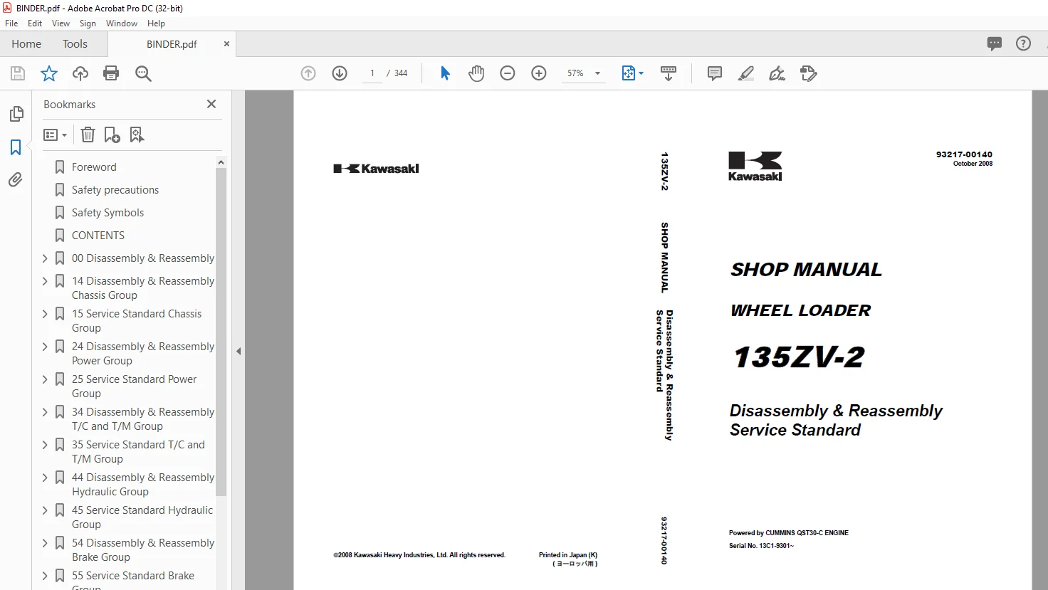
Kawasaki WHEEL LOADER 135IV-2 SHOP MANUAL 93217-00140 – PDF DOWNLOAD
135ZV-2
Disassembly & Reassembly
Service Standard
Description
Kawasaki WHEEL LOADER 135IV-2 SHOP MANUAL 93217-00140 – PDF DOWNLOAD
FILE DETAILS:
Kawasaki WHEEL LOADER 135IV-2 SHOP MANUAL 93217-00140 – PDF DOWNLOAD
Language :English
Pages :344
Downloadable : Yes
File Type : PDF
IMAGES PREVIEW OF THE MANUAL:
DESCRIPRION:
Kawasaki WHEEL LOADER 135IV-2 SHOP MANUAL 93217-00140 – PDF DOWNLOAD
135ZV-2
Disassembly & Reassembly
Service Standard
Foreword
- To ensure good machine performance, reduce failures or problems, and prolong the service life of each component,
it is necessary to operate the machine as is directed in the Operator and Maintenance Manual. - To effectively diagnose and repair the machine, it is important to follow the guidelines laid out in this Shop Manual.
Disassembly & Reassembly - Service Standard
- For the engine, refer to the engine Shop Manual provided by the engine manufacturer.The purpose of this manual is to provide information on the product and the correct maintenance and repair methods.
- Please read this manual to ensure correct troubleshooting and good repair service.
This manual will be periodically reviewed and revised for more satisfactory content. - If you have any opinion or requests, please inform us.
Safety precautions
- The most important point in providing repair service is safety.
- To ensure safety, observe the general cautions described below. – This manual is intended for properly trained and equipped service technicians. – Any work on the machine must be performed by the trained personnel only.
- – Carefully read this manual to thoroughly understand the operation method before you operate or repair the machine.
- – Be sure to wear appropriate clothes and protectors, such as safety boots, hard hat and goggles. – Place the machine on level and solid ground, and place chocks against the wheels to prevent movement.
- – Remove the cable from the battery before starting the service work, and attach a “DO NOT OPERATE!” tag to the operation board.
IMPORTANT
If a battery terminal is removed from a machine in less than 30 seconds after the key is put into the “OFF” position, it can corrupt the ECM program, which can disable the engine. Always wait 1 full minute to be sure to be past this “write to memory function” prior to removing battery terminals
- – Be sure to release the internal pressure before you remove a pipe, such as the hydraulic oil, air, or engine coolant pipe. – Be sure to apply the articulation stopper before starting work. – While supporting the bottom of the chassis using a jack, be sure to support the chassis using the blocks.
- When the boom or bucket is raised or when a unit is lifted by a crane, be sure to place a stand or adequate cribbing under the unit to prevent unexpected dropping. – Do not start to work in an enclosed area if adequate ventilation is not provided. – To remove a heavy unit (20 kgf (40 lbs) or more), be sure to use a crane or other lifting device. – Just after stopping operation, be careful not to directly touch a hot component. You may get burned.
- – Contact tire manufacturer’s local dealer for tire servicing and changing. – Always store the tools in good condition, and use them properly.
- – Keep the work area clean. Clean up spills immediately. – Avoid the use of flammable solvents and cleaners. – When working outdoors keep work areas, ladders, steps, decks and work platforms clear of snow, ice, and mud. – Use safe work platforms to reach higher areas of the machine.
- – Any technician that operates a refrigerant recovery and recycling machine must first be certified through IMPORTANT an EPA approved testing program. If a battery terminal is removed from a machine in less than 30 seconds after the key is put into the “OFF” position, it can corrupt the ECM program, which can disable the engine.
- Always wait 1 full minute to be sure to be past this “write to memory function” prior to removing battery terminals.
- TABLE OF CONTENTS:
Kawasaki WHEEL LOADER 135IV-2 SHOP MANUAL 93217-00140 – PDF DOWNLOAD
135ZV-2
Disassembly & Reassembly
Service Standard
135ZV-2 Disassembly & Reassembly 00-1
Symbols 00-2
Weight of Main Components 00-3
Bolt Tightening Torque 00-4
Hose Band Tightening Torque 00-8
Liquid Gasket and Screw Lock Agent 00-9
Cautions regarding parts removal 00-9
Cautions regarding reassembly 00-9
Screw lock agent application procedure 00-9
How to wind a seal tape 00-10
Cautions Regarding Welding Repair Service 00-11
Applying and Storing Articulation Stopper 00-13
Applying articulation stopper 00-13
Storing articulation stopper 00-13
135ZV-2 Disassembly & Reassembly Chassis Group 14-1
Deck 14-2
Deck removing and installing 14-2
Fuel Tank 14-4
Fuel tank removing and installing 14-4
Hydraulic Tank 14-6
Hydraulic tank removing and installing 14-6
Engine Room 14-8
Engine room removing and installing 14-8
ROPS 14-12
ROPS removing and installing 14-12
Cab 14-13
Cab removing and installing 14-13
Floor Board 14-15
Floor board removing and installing 14-15
Boom 14-18
Boom removing and installing 14-18
Center Pin 14-21
Upper center pin 14-21
Lower center pin 14-22
Center pin removing and installing 14-23
135ZV-2 Service Standard Chassis Group 15-1
Linkage 15-2
Linkage Pin Standard Clearance Values 15-3
Liner clearance adjustment 15-3
Shim adjustment 15-4
Center Pin 15-6
Center pin shim adjustment 15-6
Bearing cover installing 15-6
Lower center pin bearing outer ring installing 15-7
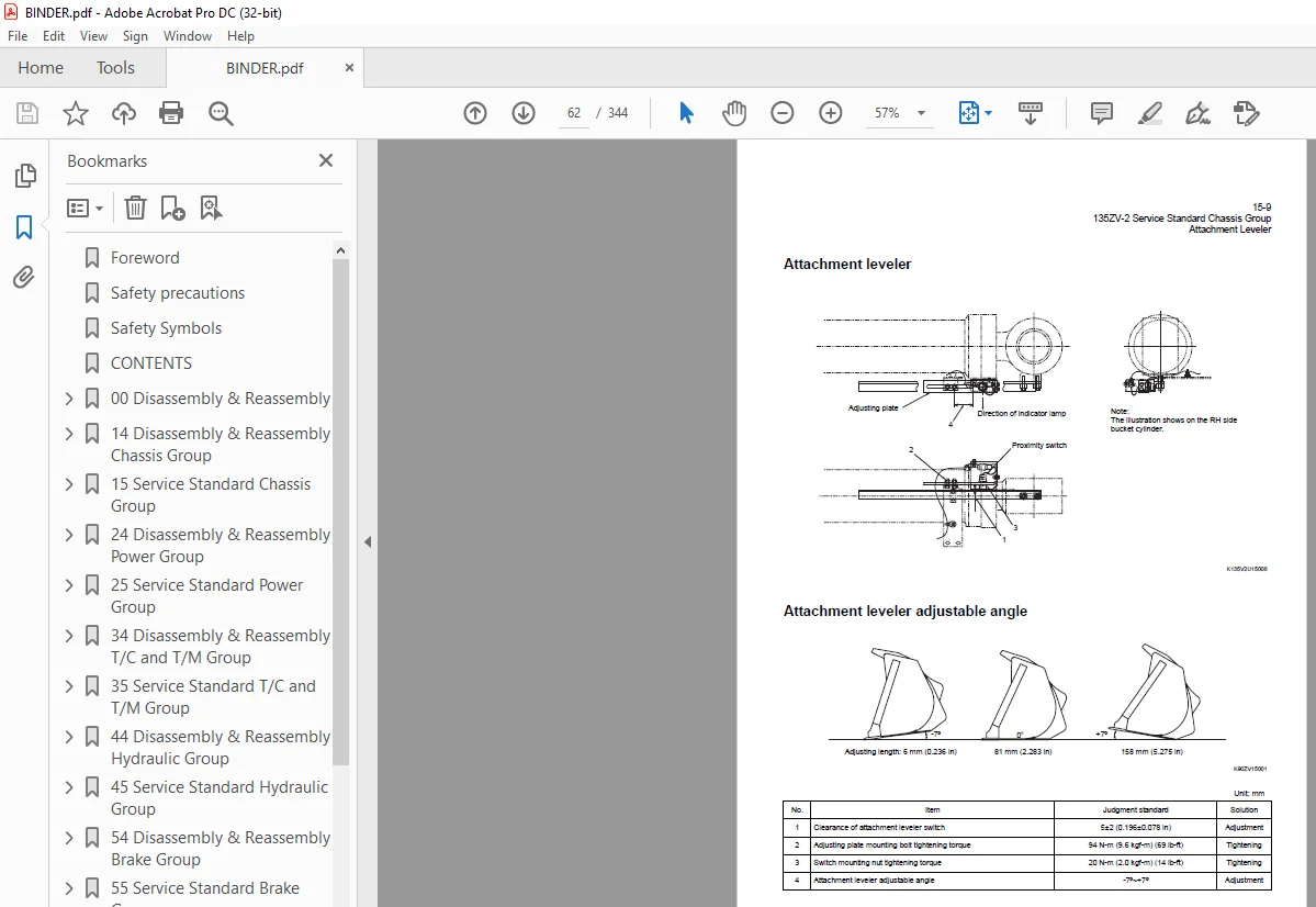
Attachment Leveler 15-8
Attachment leveler 15-9
Attachment leveler adjustable angle 15-9
135ZV-2 Disassembly & Reassembly Power Group 24-1
Power Line 24-2
Power line tightening torque 24-2
Radiator 24-3
Radiator tightening torque 24-3
Radiator removing and installing 24-4
Torque Converter Oil Cooler 24-7
Torque converter oil cooler removing and installing 24-7
Fan 24-9
Fan removing and installing 24-9
Engine 24-11
Engine removing and installing 24-11
Propeller Shaft 24-14
Propeller shaft removing and installing 24-14
Air Cleaner 24-17
Air cleaner removing and installing 24-17
Muffler 24-19
Muffler removing and installing 24-19
Front Axle Assembly 24-20
Front axle assembly tightening torque 24-20
Front axle assembly removing and installing 24-22
Front axle disassembling and assembling 24-25
Front axle assembly cautions 24-29
Spider Assembly 24-33
Spider assembly disassembling and assembling 24-33
Special Tool 24-34
Special tool for axle 24-34
Rear Axle Assembly 24-38
Rear axle assembly tightening torque 24-38
Rear axle assembly removing and installing 24-40
Rear axle disassembling and assembling 24-43
Axle Support 24-44
Axle support tightening torque 24-44
Axle support disassembling and assembling 24-45
Axle support assembly cautions 24-46
Differential Assembly 24-47
Differential assembly removing and installing 24-47
Differential assembly disassembling and assembling 24-50
135ZV-2 Service Standard Power Group 25-1
Propeller Shaft Service Standard 25-2
Axle and Differential Service Standard 25-3
Axle group 25-3
Differential 25-4
135ZV-2 Disassembly & Reassembly Torque Converter and Transmission Group 34-1
Torque Converter and Transmission Assembly 34-2
Torque converter and transmission assembly tightening torque 34-2
Torque Converter Assembly 34-3
Torque converter removing and installing 34-3
Torque converter assembly bolt tightening torque 34-6
Torque converter assembly disassembling and assembling 34-7
Transmission Assembly 34-13
Transmission removing and installing 34-13
Transmission assembly bolt tightening torque 34-18
Transmission assembly disassembling and assembling 34-19
Clutch Assembly 34-28
Clutch assembly disassembling and assembling 34-28
Clutch Spider Assembly 34-42
Forward and 3rd clutch spiders disassembling and assembling 34-42
2nd Clutch Spider 34-44
2nd clutch spider disassembling and assembling 34-44
Reverse Clutch Spider 34-46
Reverse clutch spider disassembling and assembling 34-46
1st Clutch Assembly 34-48
1st clutch assembly disassembling and assembling 34-48
Input Gear Box Assembly 34-51
Input gear box disassembling and assembling 34-51
Control Valve Assembly 34-53
Control valve removing and installing 34-53
Control valve disassembling and assembling 34-56
Special Tool 34-58
135ZV-2 Service Standard Torque Converter and Transmission Group 35-1
Transmission Assembly 35-2
Transmission 35-2
Torque converter 35-3
Torque Converter Gear Pump 35-6
Gear pump specifications 35-7
Clutch Train and Number of Teeth 35-8
Clutch specifications 35-9
Clutch Oil Pressure 35-10
135ZV-2 Disassembly & Reassembly Hydraulic Group 44-1
Hydraulic Parts Removal and Installation Warning 44-2
Hydraulic Parts Disassembly and Assembly Cautions 44-3
Hydraulic parts disassembly cautions 44-3
Hydraulic parts assembly cautions 44-3
Hydraulic Pump 44-4
Hydraulic pump removing and installing 44-4
Hydraulic pump assembly disassembling and assembling 44-10
Regulator disassembling and assembling 44-16
Hydraulic pilot (triple) pump disassembling and assembling 44-23
Pilot Valve (for Loading) 44-24
Pilot valve (for loading) removing and installing 44-24
Pilot valve (for loading) disassembling and assembling 44-26
Pilot Valve (for Steering) 44-33
Pilot valve (for steering) removing and installing 44-33
Pilot valve (for steering) disassembling and assembling 44-35
Steering Valve 44-39
Steering valve removing and installing 44-39
Steering valve disassembling and assembling 44-42
Multiple Control Valve 44-46
Multiple control valve removing and installing 44-46
Multiple control valve disassembling and assembling 44-49
Stop Valve 44-54
Stop valve removing and installing 44-54
Stop valve disassembling and assembling 44-56
Hydraulic Cylinder 44-58
Hydraulic cylinder removing and installing 44-58
Boom cylinder removing and installing 44-58
Bucket cylinder removing and installing 44-61
Steering cylinder removing and installing 44-63
Hydraulic cylinder disassembling and assembling 44-66
Special tool for hydraulic cylinder disassembling 44-73
135ZV-2 Service Standard Hydraulic Group 45-1
Hydraulic Cylinder 45-2
135ZV-2 Disassembly & Reassembly Brake Group 54-1
Brake Valve 54-2
Brake valve removing and installing 54-2
Brake valve disassembling and assembling 54-4
Unloader Valve 54-10
Unloader valve removing and installing 54-10
Unloader valve disassembling and assembling 54-12
Manifold Valve Assembly 54-14
Valve assembly removing and installing 54-14
Valve assembly disassembling and assembling 54-16
Accumulator 54-17
Accumulator removing and installing 54-17
Accumulator disassembling and assembling 54-19
Nitrogen gas charging 54-25
Service Brake 54-27
Service brake disassembling and assembling 54-27
Parking Brake 54-31
Parking brake removing and installing 54-31
Parking brake disassembling and assembling 54-32
135ZV-2 Service Standard Brake Group 55-1
Brake Valve 55-2
Service Brake 55-4
Parking Brake 55-5
135ZV-2 Disassembly & Reassembly Operator Station Group 74-1
Air Conditioner 74-2
Air conditioner removing and installing 74-2
Air conditioner disassembling and assembling 74-4
135ZV-2 Service Standard Operator Station Group 75-1
Air Conditioner 75-2
Air conditioner periodical inspection/servicing 75-2
Air conditioner tightening torque 75-2
S.M 29/01/25