Kawasaki WHEEL LOADER 60ZV-2 SHOP Manual 93206-00111 – PDF DOWNLOAD
$29.95
Kawasaki WHEEL LOADER 60ZV-2 SHOP Manual 93206-00111 – PDF DOWNLOAD
General Information
Standard Measurement Values for
Performance Check
Function & Structure
Check & Adjustment
Powered by CUMMINS QSB4.5 Engine
Serial No. 60C3-5001~
Description
Kawasaki WHEEL LOADER 60ZV-2 SHOP Manual 93206-00111 – PDF DOWNLOAD
FILE DETAILS:
Kawasaki WHEEL LOADER 60ZV-2 SHOP Manual 93206-00111 – PDF DOWNLOAD
Language :English
Pages :324
Downloadable : Yes
File Type : PDF
IMAGES PREVIEW OF THE MANUAL:
DESCRIPRION:
Kawasaki WHEEL LOADER 60ZV-2 SHOP Manual 93206-00111 – PDF DOWNLOAD
General Information
Standard Measurement Values for
Performance Check
Function & Structure
Check & Adjustment
Powered by CUMMINS QSB4.5 Engine
Serial No. 60C3-5001~
Foreword
- To ensure good machine performance, reduce failures or problems, and prolong the service life of each component,
it is necessary to operate the machine as is directed in the Operator and Maintenance Manual. - To effectively diagnose and repair the machine, it is important to follow the guidelines laid out in this Shop Manual.
General Information
Functions and structure
- For the engine, refer to the engine Shop Manual provided by the engine manufacturer.
- The purpose of this manual is to provide information on the product and the correct maintenance and repair methods.
Please read this manual to ensure correct troubleshooting and good repair service. - This manual will be periodically reviewed and revised for more satisfactory content. If you have any opinion or
requests, please inform us.
Safety Symbols
An accident may occur if you disregard safety rules. In this manual, several expressions are used according to levels of danger for inspection and repair work as shown below. Read the work procedures and cautions described in this manual, and take preventive measures against possible problems before starting service work.
TABLE OF CONTENTS:
Kawasaki WHEEL LOADER 60ZV-2 SHOP Manual 93206-00111 – PDF DOWNLOAD
General Information
Standard Measurement Values for
Performance Check
Function & Structure
Check & Adjustment
Powered by CUMMINS QSB4.5 Engine
Serial No. 60C3-5001~
Foreword 4
Safety Symbols 5
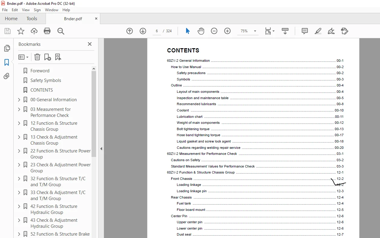
CONTENTS 6
00 General Information 14
How to Use Manual 15
Safety precautions 15
Symbols 16
Outline 17
Layout of main components 17
Inspection and maintenance table 18
Recommended lubricants 21
Coolant 23
Coolant specification 23
Recommended mixture of antifreeze 23
Lubrication chart 24
Weight of main components 25
Bolt tightening torque 26
Hexagon bolt 26
Flanged hexagon bolt 29
Hose band tightening torque 30
Liquid gasket and screw lock agent 31
Cautions regarding parts removal 31
Cautions regarding reassembly 31
Screw lock agent application procedure 32
How to wind a seal tape 32
Cautions regarding welding repair service 33
03 Measurement for Performance Check 36
Cautions on Safety 37
Standard Measurement Values for Performance Check 38
12 Function & Structure Chassis Group 40
Front Chassis 41
Loading linkage 41
Loading linkage pin 42
Rear Chassis 43
Fuel tank 43
Floor board mount 44
Floor board 44
Viscous mount 44
Center Pin 45
Upper center pin 45
Lower center pin 45
Dust seal 46
13 Check & Adjustment Chassis Group 48
Linkage Pin 49
Liner 49
Liner adjustment 50
Center Pin 51
Adjusting shim 51
Installing bearing cover 51
22 Function & Structure Power Group 52
Power Line 53
Engine / Transmission 54
Engine / transmission mount 54
Radiator 55
Propeller Shaft 57
Second propeller shaft assembly 58
Third propeller shaft assembly 59
Axle Assembly 60
Axle Support 61
Differential Gear 63
Function of TPD 64
Difference in gear shapes 64
Contact between pinion and side gear 64
Operation of TPD 65
23 Check & Adjustment Power Group 66
Engine 67
Measuring engine speed 67
Measuring engine oil pressure 67
Propeller Shaft 68
Propeller shaft phase 68
Second propeller shaft alignment 68
Tightening torque 69
Axle 70
Axle 70
Differential gear 71
Adjusting tooth contact 72
32 Function & Structure T/C and T/M Group 74
Torque Converter 75
Torque converter structure 75
Power flow path 75
Torque multiplication 75
Torque Converter Gear Pump 76
Gear pump specifications 76
Transmission 77
Gear arrangement 77
Clutch specifications 78
Friction plate: mm (in) 78
Valve location 79
Clutch Pack 80
Forward and 2nd speed clutch 80
Reverse and 1st speed clutch 81
3rd speed clutch 82
Power Flow Path in the Transmission 83
Forward 1st speed power flow path 83
Forward 2nd speed power flow path 83
Forward 3rd speed power flow path 84
Reverse 1st speed power flow path 84
Reverse 2nd and 3rd speeds power flow paths 84
Hydraulic System Diagram 85
Hydraulic Circuit Diagram 86
Oil Flow 87
Oil flow in the torque converter line 87
From the torque converter pump to torque converter 87
From torque converter to cooling circuit 87
From cooler to lubrication circuit 87
Oil flow to the clutch 87
T/C and T/M Oil Circulation 88
Control Valve 89
System diagram 91
Modulation Mechanism 92
Clutch control oil pressure curve 92
Before the shift lever is moved (travelling or stop condition) 93
When the shift lever is moved (1) 94
When the shift lever is moved (2) 95
Accumulator 96
Accumulator for 1st speed clutch 96
Clutch Solenoid Valve 98
For forward/reverse and speed clutches 98
After power-off (clutch disengaged status) 98
After power-on (clutch engaged status) 99
33 Check & Adjustment T/C and T/M Group100
Clutch Oil Pressure101
42 Function & Structure Hydraulic Group102
Flushing Hydraulic Lines103
Purpose of flushing103
Cautions on Hydraulic Parts Replacement104
Hydraulic Circuit Symbols105
Hydraulic lines105
Pumps & motors105
Cylinders105
Operation methods106
Pressure control valve106
Flow control valve106
Directional control valve107
Check valve107
Miscellaneous hydraulic symbols108
Layout of Hydraulic Units109
Hydraulic Tank110
Hydraulic tank breather valve (tank cap)111
Hydraulic tank specifications112
Hydraulic oil level check112
Hydraulic Pump113
Hydraulic pump specifications113
Hydraulic pump principle114
Hydraulic pump wear plate115
Hydraulic pump bushing lubrication115
Hydraulic Cylinder116
Boom cylinder116
Bucket cylinder116
Steering cylinder117
Hydraulic cylinder specifications118
Return Filter119
Return filter specifications119
Loading System120
Relief Valve Assembly121
Relief valve operation122
Check valve operation122
Accumulator123
Accumulator specifications123
Pilot Valve (TH40MS)124
Pilot valve specifications125
Pilot valve performance chart125
Pilot valve operation127
Multiple Control Valve (KVS-120H-2)129
Multiple control valve specifications130
Multiple control valve main relief valve131
Main relief valve operation131
Adjusting set pressure132
Multiple control valve overload relief valve133
Overload relief valve operation133
Adjusting set pressure134
Multiple control valve make-up valve134
Make-up valve operation134
Multiple control valve bucket spool135
Bucket spool operation135
Multiple control valve boom spool137
Boom spool operation137
Elbow Adapter140
Pilot Valve Filter141
Steering System142
Priority Valve144
Priority valve specifications144
Priority valve operation145
Relief valve operation147
Orbitrol®148
Orbitrol® construction148
Valve part148
Rotor part149
Orbitrol® specification149
Orbitrol® operation150
Neutral150
Turn151
Orbitrol® feed-back mechanism operation152
Steering speed and flow rate control153
Hydraulic pump oil amount and steering force153
Orbit rotor operation principle154
Auxiliary valves155
Overload relief valve and make-up valve156
Emergency check valve157
Inlet check valve157
Cushion Valve158
Cushion valve specifications159
Cushion valve operation159
43 Check & Adjustment Hydraulic Group162
Loading/Steering Circuit Relief Valve163
Loading circuit relief valve setting pressures163
Measuring loading circuit main relief pressure164
Measuring loading circuit overload relief pressure166
Measuring pilot circuit relief pressure167
Steering circuit relief valve setting pressures168
Measuring steering circuit main relief pressure169
Adjusting steering line main pressure170
Measuring steering circuit overload relief pressure171
Hydraulic Cylinder172
Cylinder natural drift172
52 Function & Structure Brake Group174
Brake Circuit175
Brake Units Layout176
Hydraulic Servo Master Cylinder177
Hydraulic servo master cylinder specifications178
Performance diagram178
Hydraulic servo master cylinder operation179
No braking (when the brake is released)179
Braking179
When the brake is in the hold (balanced) position180
When the pedal is depressed a second time180
Braking in case of one brake system failing180
Braking in case of pump failure180
Pressure Difference Switch181
Service Brake182
Service brake operation182
Service brake friction plate183
Service brake steel plate183
Brake circuit air bleeding procedure184
Parking Brake185
Brake Control186
Service brake linkage186
Parking brake linkage187
Brake Oil Reservoir188
Brake oil reservoir specifications188
53 Check & Adjustment Brake Group190
Hydraulic Servo Master191
Hydraulic servo master performance inspection191
Service Brake193
Service brake performance check193
Service brake friction plate wear measurement194
Parking Brake195
Parking brake performance check195
Parking brake clearance adjustment196
Adjustment procedure196
Brake lining abrasion check197
Brake Control198
Adjusting brake pedal and switch198
Adjusting right brake pedal198
Adjusting left brake pedal199
Adjusting switch200
Parking brake linkage adjustment200
62 Function & Structure Electrical Group202
How to Use Electrical Wiring Diagram203
Electrical Cable Color Codes204
Electrical Circuit Symbols205
Sensor Mount206
Fuse207
Fuse box207
Fusible link209
Engine Start Circuit210
Engine start circuit diagram210
Neutral starter211
Shift lever neutral (N) position211
Shift lever forward/reverse (F/R) position211
Starter switch212
ECM safety features213
Battery relay213
Battery relay operation213
Alternator I terminal wire214
Diode unit214
Neutral relay215
Magnet switch216
Voltage relay216
Power Generating/Charging Circuit217
Alternator217
ECM (Engine Controller)218
Function of ECM218
Connection diagram218
Monitor lamp test219
Failure diagnosis220
Engine diagnostic switch (option)220
Failure diagnostic chart221
Increment decrement switch (option)222
Quantum fault code information223
Accelerator pedal230
Accelerator pedal installation231
Transmission Control Circuit and Monitor Circuit232
Machine control unit (MCU)232
LED inspection windows233
Machine control unit (MCU) connection diagram234
Machine control unit (MCU) function235
Forward/reverse (F/R) shifting and speed change235
Automatic shift237
Machine speed sensor238
Downshift button operation239
Declutch240
Back-up alarm241
Forward/reverse clutch cut-off when parking brake ON242
Parking relay243
Limit switch243
Machine control unit (MCU) failure warning244
MCU failure relay244
Speedometer245
Warning for brake oil pressure /level failure245
Monitoring system246
Items to be monitored and operation condition246
Operation monitor lamps247
Instrument Panel and Switch248
Instrument panel248
Instrument panel rear surface249
Gauge circuit250
Fuel level sensor252
Electrical Detent Circuit253
Bucket leveler253
Boom kick-out253
Proximity switch254
Detent solenoid254
Diode255
Diode check method256
Caution for diode check method256
Continuity check mode256
Diode check mode256
Resistance check mode257
Surge voltage and surge suppression diodes258
Diagnostic System259
Diagnostic system flow259
Diagnostic failure history memory data260
Warning monitor/control260
Failure code261
Malfunction mode symbol262
Diagnostic (MCU) failure code detection condition263
Fault diagnostic result storage condition263
Diagnostic failure history indication and deletion264
Failure history indication264
Failure history deletion264
Diagnostic switch266
63 Check & Adjustment Electrical Group268
Cautions Regarding Electric Circuit Check269
Disconnecting or reinstalling connector269
How to attach the probes of the circuit tester271
Electrical Transmission Control System Troubleshooting Flowchart272
Standard troubleshooting flowchart272
MCU Abnormal Operation Judgment273
MCU check273
When the “MCU failure” monitor lamp lights:273
When the output units (solenoid valve, etc) do not operate properly:273
If the input units or circuit are not defective274
MCU LED indicator275
Electrical Circuit Check277
Shift lever input electrical circuit check277
Declutch input electrical circuit check279
Downshift button input electrical circuit check281
Machine speed sensor input electrical circuit check282
Clutch solenoid valve output electrical circuit check283
Neutral relay electrical circuit check286
Checking parking brake circuit288
Gauge circuit electrical circuit check289
Bucket leveler electrical circuit check292
INDEX294
Maintenance Log299
Notes303
Axle Assembly308
Torque Converter and Transmission309
Loading/Steering Hydraulic Line310
Brake Circuit311
Electrical Wiring Diagram (1/2)312
Electrical Wiring Diagram (2/2)313
Electrical Wiring Diagram314
Electrical wiring diagram abbreviation chart314
Electrical Connection Diagram315
Electrical Wiring Diagram (CAB)316
Electrical Equipment Layout318
Front chassis318
Rear chassis320
Floor board323
S.M 2/2/25