Kawasaki WHEEL LOADER 65TMV SHOP MANUAL 93207-00233 – PDF DOWNLOAD
$28.95
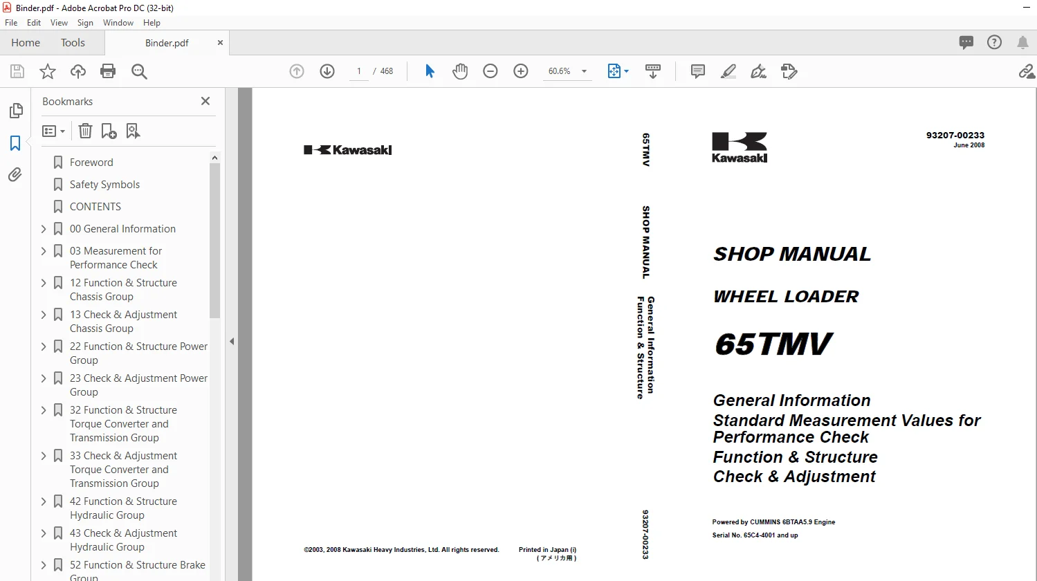
Kawasaki WHEEL LOADER 65TMV SHOP MANUAL 93207-00233 – PDF DOWNLOAD
General Information
Standard Measurement Values for
Performance Check
Function & Structure
Check & Adjustment
Powered by CUMMINS 6BTAA5.9 Engine
Serial No. 65C4-4001 and up
Description
Kawasaki WHEEL LOADER 65TMV SHOP MANUAL 93207-00233 – PDF DOWNLOAD
FILE DETAILS:
Kawasaki WHEEL LOADER 65TMV SHOP MANUAL 93207-00233 – PDF DOWNLOAD
Language :English
Pages :468
Downloadable : Yes
File Type : PDF
IMAGES PREVIEW OF THE MANUAL:
DESCRIPTION:
Kawasaki WHEEL LOADER 65TMV SHOP MANUAL 93207-00233 – PDF DOWNLOAD
General Information
Standard Measurement Values for
Performance Check
Function & Structure
Check & Adjustment
Powered by CUMMINS 6BTAA5.9 Engine
Serial No. 65C4-4001 and up
Foreword
- To ensure good machine performance, reduce failures or problems, and prolong the service life of each component,
it is necessary to operate the machine as is directed in the Operator and Maintenance Manual. - To effectively diagnose and repair the machine, it is important to follow the guidelines laid out in this Shop Manual.
General Information
Function and structure
- For the engine, refer to the engine Shop Manual provided by the engine manufacturer.
- The purpose of this manual is to provide information on the product and the correct maintenance and repair methods.
Please read this manual to ensure correct troubleshooting and good repair service. - This manual will be periodically reviewed and revised for more satisfactory content. If you have any opinion or
requests, please inform us.
Safety Symbols
An accident may occur if you disregard safety rules.
In this manual, several expressions are used according to levels of danger for inspection and repair work as shown
below. Read the work procedures and cautions described in this manual, and take preventive measures against
possible problems before starting service work.
TABLE OF CONTENTS:
Kawasaki WHEEL LOADER 65TMV SHOP MANUAL 93207-00233 – PDF DOWNLOAD
General Information
Standard Measurement Values for
Performance Check
Function & Structure
Check & Adjustment
Powered by CUMMINS 6BTAA5.9 Engine
Serial No. 65C4-4001 and up
Foreword 4
Safety Symbols 5
CONTENTS 6
00 General Information 18
How to Use Manual 19
Outline 21
03 Measurement for Performance Check 40
Cautions on Safety 41
Standard Measurement Values for Performance Check 42
12 Function & Structure Chassis Group 44
Front Chassis 45
Rear Chassis 48
Center Pin 50
13 Check & Adjustment Chassis Group 52
Linkage Pin 53
Center Pin 55
22 Function & Structure Power Group 56
Power Line 57
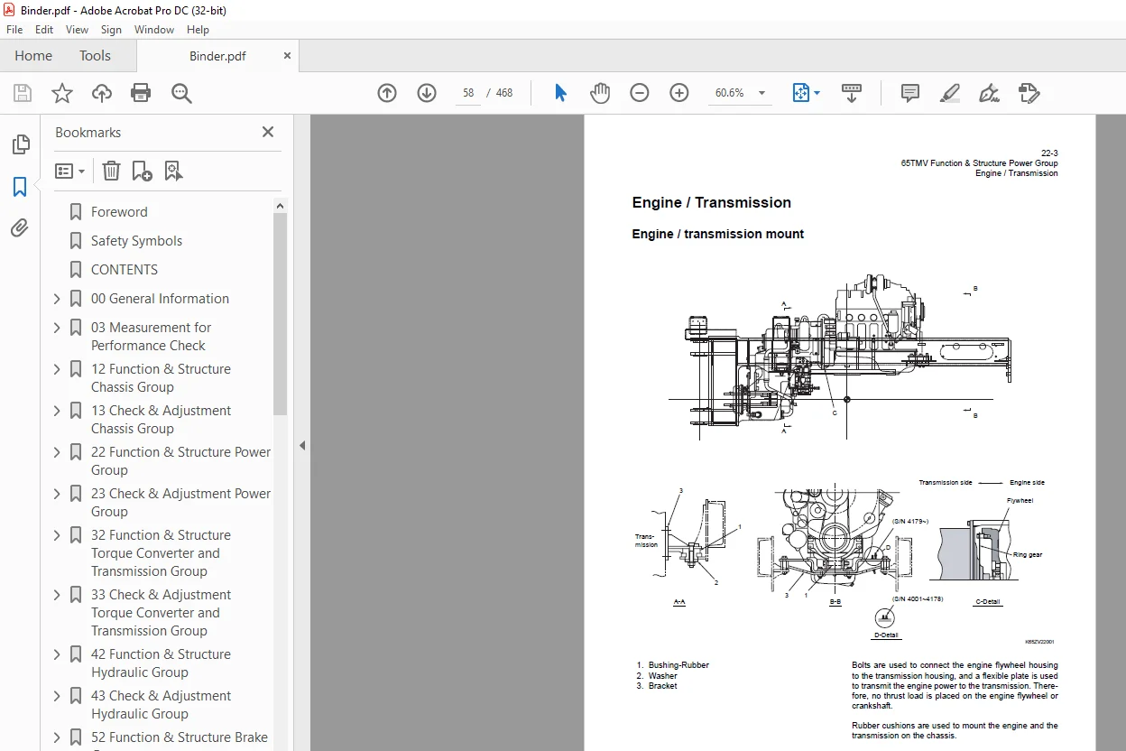
Engine / Transmission 58
Radiator 62
Propeller Shaft 64
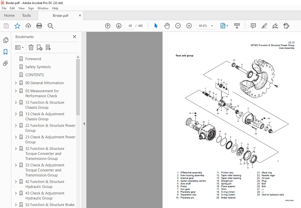
Axle Assembly 67
Axle Support 69
Differential Gear 71
23 Check & Adjustment Power Group 76
Engine 77
Propeller Shaft 78
Axle 80
32 Function & Structure Torque Converter and Transmission Group 86
Torque Converter 87
Torque Converter Gear Pump 88
Transmission 89
Clutch Pack 94
Power Flow Path in the Transmission 97
Hydraulic System Diagram 102
Hydraulic Circuit Diagram 103
Oil Flow 104
T/C and T/M Oil Circulation 105
Control Valve 106
Modulation Mechanism 108
Accumulator 112
Clutch Solenoid Valve 113
33 Check & Adjustment Torque Converter and Transmission Group 116
Clutch Oil Pressure 117
42 Function & Structure Hydraulic Group 120
Flushing Hydraulic Circuit 121
Cautions on Hydraulic Parts Replacement 122
Hydraulic Circuit Symbols 123
Hydraulic System Operation 127
Layout of Hydraulic Units 129
Hydraulic Tank 130
Hydraulic Pump 136
Hydraulic Cylinder 139
Loading System 142
Reducing Valve (for Pilot Pressure) 143
Pilot Valve (S/N 4001~4030) 144
Pilot Valve (TH40MS) (S/N 4031~) 146
Multiple Control Valve (KML22/2T) 151
Two-speed Dump Function 162
Adapter (Orifice) 165
Ride Control (OPT) 166
Steering System 176
Orbitrol® 177
Steering Valve (KVS25-A3 0/20) 184
Stop Valve 196
Reducing Valve (for Orbitrol®) 199
Steering Line Filter 200
Steering System (Direct Acting Orbitrol®) (OPT) 201
Emergency Steering (OPT) 217
Fan Motor System 220
Fan Motor Line 221
Reversing Fan Motor (OPT) 229
Reversing Fan Motor Line (OPT) 231
43 Check & Adjustment Hydraulic Group 238
Loading/Steering Circuit Relief Valve 239
Hydraulic Cylinder 250
Stop Valve 252
Fan Revolution 253
52 Function & Structure Brake Group 256
Brake System Outline 257
Brake Units Layout 258
Unloader Valve 259
Valve Unit 262
Brake Accumulator Line 263
Brake Valve 266
Service Brake 273
Parking Brake 277
Parking Brake Manual Release 281
Parking Brake Spring Chamber 283
Brake Circuit Check Valve 285
53 Check & Adjustment Brake Group 286
Brake Circuit Oil Pressure 287
Service Brake 291
Parking Brake 293
62 Electrical Group 296
How to Use Electrical Wiring Diagram 297
Electrical Cable Color Codes 298
Electrical Circuit Symbols 299
Sensor Mount 300
Fuse 301
Engine Start Circuit 304
Power Generating / Charging Circuit 311
Transmission Control Circuit and Monitor Circuit 312
Instrument Panel and Switch 330
Electrical Detent Circuit 335
Diode 339
Diagnostic System 343
63 Check & Adjustment Electrical Group 352
Cautions Regarding Electric Circuit Check 353
Electrical Transmission Control System Troubleshooting Flowchart 356
Transmission Controller Abnormal Operation Judgment 357
Electrical Circuit Check 361
72 Function & Structure Air Conditioner Group 376
Air Conditioner 377
Electrical Connections 387
Maintenance 398
A/C Charging 404
Troubleshooting 409
INDEX 422
Axle Assembly 436
Torque Converter and Transmission 437
Loading/Steering Hydraulic Line 438
Loading/Steering Hydraulic Line (for Direct Acting Orbitrol®) (Option) 439
Brake Circuit 440
Electrical wiring diagram abbreviation chart 441
Electrical Wiring Diagram 442
(S/N 4001~4076) (1/2) 442
(S/N 4001~4076) (2/2) 443
(S/N 4077~4078) (1/2) 444
(S/N 4077~4078) (2/2) 445
(S/N 4079~4114) (1/2) 446
(S/N 4079~4114) (2/2) 447
(S/N 4115~4192) (1/2) 448
(S/N 4115~4192) (2/2) 449
(S/N 4193~) (1/2) 450
(S/N 4193~) (2/2) 451
Electrical Connection Diagram 452
(S/N 4001~4076) 452
(S/N 4077~) 453
Electrical Connections (Air Conditioner) (S/N 4001~4126) 454
Electrical Wiring (Reversal Fan) (OPT) 455
Electrical Wiring Diagram (CAB) 456
Electrical Equipment Layout 458
Front chassis 458
Rear chassis 461
Floor board 465
S.M 5/2/2025