Kawasaki Wheel Loader 67ZV7 Service manual + Parts manual + Wiring diagrams + Troubleshooting manual – PDF DOWNLOAD
Original price was: $96.95.$39.95Current price is: $39.95.
Kawasaki Wheel Loader 67ZV7 Service manual + Parts manual + Wiring diagrams + Troubleshooting manual
Description
Kawasaki Wheel Loader 67ZV7 Service manual + Parts manual + Wiring diagrams + Troubleshooting manual
File Details:
Kawasaki Wheel Loader 67ZV7 Service manual + Parts manual + Wiring diagrams + Troubleshooting manual
Language : English
Pages : 500+
Size : 268 MB
Downloadable : Yes
Format : PDF
KAWASAKI WHEEL LOADER 67ZV7 SERVICE MANUAL + PARTS MANUAL + WIRING DIAGRAMS + TROUBLESHOOTING MANUAL – PDF DOWNLOAD:
Image Preview:
Table of Contents:
Kawasaki Wheel Loader 67ZV7 Service manual + Parts manual + Wiring diagrams + Troubleshooting manual
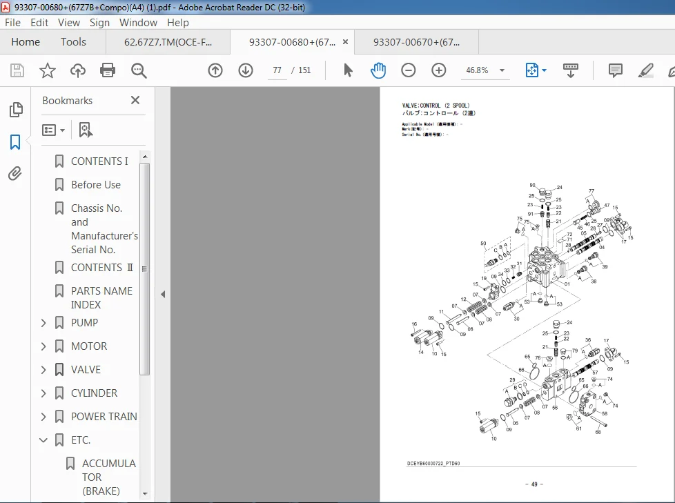
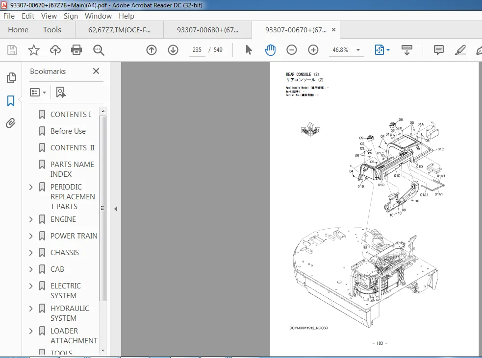
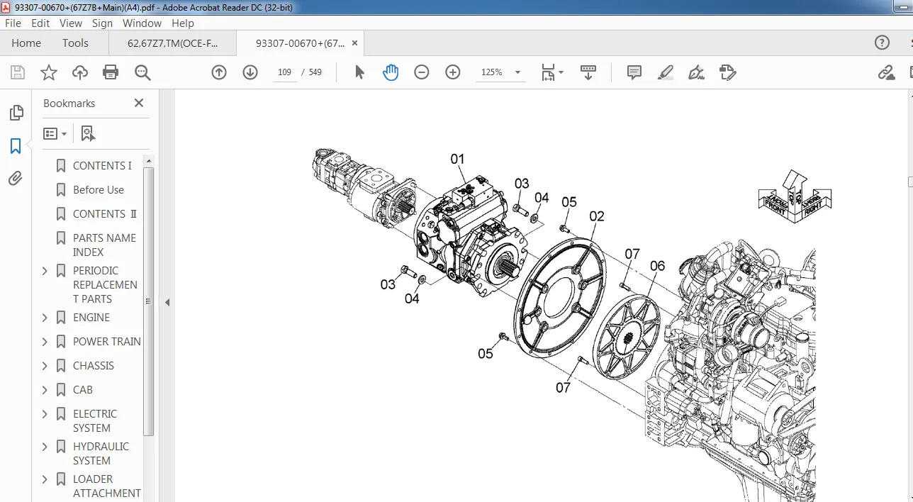
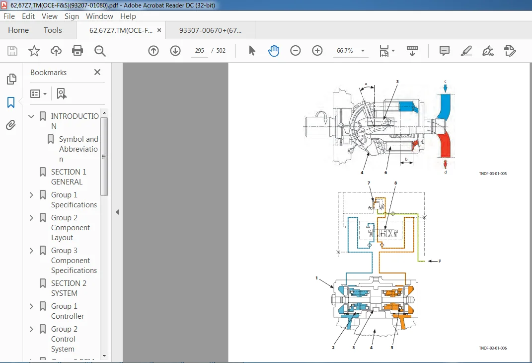
SECTION 1 GENERAL TOC....................................................  7
1 Specifications.........................................................  9
	Specifications(62Z7/67Z7)............................................  9
	Specifications (67TM7)............................................... 10
2 Component Layout....................................................... 11
	Main Component Layout (Overview)..................................... 11
	Main Component Layout (Hydraulic System)............................. 13
	Main Component Layout (Travel System)................................ 15
	Electrical System (Overview)......................................... 16
	Electrical System (Cab).............................................. 17
	Engine............................................................... 23
	Exhaust Filter....................................................... 25
	HST Pump, 4-Gear Pump Unit........................................... 26
	Transmission, HST Motor.............................................. 27
	Control Valve........................................................ 27
	Manifold Valve....................................................... 28
	Brake Charge Valve................................................... 28
	Fan Valve............................................................ 29
	Fan Valve (with Fan Reverse Rotation) (Option)....................... 29
	Ride Control Valve (Option).......................................... 30
	Secondary Steering Block (Option).................................... 31
	Secondary Steering Pump (Option)..................................... 31
	Solenoid Valve (In Front Chassis).................................... 32
3 Component Specifications............................................... 33
	Engine............................................................... 33
	Engine Accessories................................................... 37
	Hydraulic Component.................................................. 39
	Electrical Component................................................. 44
SECTION 2 SYSTEM TOC..................................................... 47
1 Controller............................................................. 49
	Outline.............................................................. 49
	CAN Circuit.......................................................... 50
2 Control System......................................................... 53
	Outline.............................................................. 53
	Engine Control....................................................... 56
	HST Pump/Motor Control, Transmission Control......................... 73
	Fan Control, Valve Control...........................................107
	Control by Electric and Hydraulic Combined Circuit...................133
3 ECM System.............................................................141
	Outline..............................................................141
	Fuel Injection Control...............................................142
	Fuel Injection Amount Correction Control.............................150
	EGR Control..........................................................152
	Preheating Control...................................................154
	Alarm Control........................................................155
	Muffler Filter.......................................................156
	Operation............................................................157
	Muffler Filter Regenerative Control..................................158
	Variable Turbocharger Control........................................160
4 Hydraulic System.......................................................161
	Outline..............................................................161
	Main Circuit.........................................................162
	Steering Circuit.....................................................172
	Secondary Steering Circuit (Option)..................................180
	Pilot Circuit........................................................182
	HST Circuit..........................................................204
	Transmission Circuit.................................................212
	Fan Circuit..........................................................218
5 Electrical System......................................................225
	Outline..............................................................225
	Main Circuit.........................................................226
	Electric Power Circuit (Key Switch: OFF).............................228
	Light Bulb Check Circuit (Key Switch: ON)............................230
	CAN Circuit..........................................................232
	Accessory Circuit (Key Switch: ACC)..................................234
	Starting Circuit (Key Switch: START).................................236
	Neutral Engine Start Circuit.........................................240
	Charging Circuit (Key Switch: ON)....................................242
	Surge Voltage Prevention Circuit.....................................246
	Engine Stop Circuit..................................................248
	Auto Shut-Down Circuit (Optional)....................................250
	Steering Column Monitor Circuit......................................253
	Head Light Circuit...................................................254
	Hazard Light Circuit (Key Switch: OFF)...............................260
	Turn Signal Light Circuit:...........................................262
	Horn Circuit (Key Switch: OFF).......................................264
	Reverse Buzzer Circuit...............................................266
	Brake Light Circuit..................................................268
	Parking Brake Circuit................................................270
	Accessory Circuit....................................................275
	Work Light Circuit...................................................276
	Wiper Circuit........................................................278
	Cab Light Circuit....................................................284
SECTION 3 COMPONENT OPERATION TOC........................................287
1 Pump Device............................................................289
	Outline..............................................................289
	Rotary Group.........................................................292
	Displacement Angle Control Cylinder..................................294
	Pump Displacement Angle Control Solenoid Valve.......................298
	Forward/Reverse Control Solenoid Valve...............................302
	Cutoff Valve.........................................................304
	High-Pressure Relief Valve...........................................306
	Low-Pressure Relief Valve............................................306
	HST Charging Pump....................................................310
	4-Gear Pump Unit.....................................................311
2 HST Motor..............................................................313
	Outline..............................................................313
	Rotary Group.........................................................316
	Regulator............................................................318
	Motor Displacement Angle Control Solenoid Valve......................319
	Motor Displacement Angle Control.....................................320
	Flushing Valve.......................................................324
3 Control Valve..........................................................327
	Outline..............................................................327
	Hydraulic Circuit....................................................332
	Main Relief Valve....................................................334
	Overload Relief Valve................................................336
	Make-Up Valve........................................................342
	Flow Rate Control Valve..............................................344
4 Fan Motor and Fan Valve................................................355
	Fan Motor............................................................355
	Fan Valve............................................................356
	Fan Valve (with Fan Reverse Rotation) (OPT)..........................360
5 Steering Valve.........................................................369
	Outline..............................................................369
	Structure............................................................370
	Operation............................................................371
	Overload Relief Valve................................................374
	Make-Up Valve........................................................376
6 Priority Valve.........................................................379
	Outline..............................................................379
	Structure............................................................380
	Operation............................................................382
7 Pilot Valve............................................................389
	Outline (Joystick Type Pilot Valve for Front Attachment).............389
	Operation............................................................391
	Electromagnetic Detent...............................................398
	Outline (Fingertip Control Type Pilot Valve for Front Attachment)....399
	Operation............................................................400
	Electromagnetic Detent...............................................404
	Outline (Auxiliary Pilot Valve) (Optional)...........................405
	Operation............................................................406
	Outline (Auxiliary Pilot Valve) (Optional)...........................411
	Operation............................................................412
8 Brake Charge Valve.....................................................419
	Outline..............................................................419
	Brake Charge Valve...................................................420
9 Manifold Valve.........................................................425
	Outline..............................................................425
	Manifold Valve.......................................................426
	Pilot Reducing Valve.................................................428
	Parking Brake Solenoid Valve.........................................430
	Control Lever Lock Solenoid Valve....................................432
	Pilot Accumulator....................................................434
10 Transmission..........................................................435
	Outline..............................................................435
	Power Transmission...................................................440
	Clutch Operation.....................................................442
	Clutch Pressure Control Solenoid Valve...............................444
	Parking Brake........................................................450
11 Axle..................................................................453
	Outline..............................................................453
	Differential.........................................................454
	Torque Proportioning Differential (TPD)..............................458
	Limited Slip Differential (LSD) (Optional)...........................460
	Service Brake........................................................462
	Final Drive Planetary / Axle Shaft...................................464
12 Brake Valve...........................................................465
	Outline..............................................................465
	Operation............................................................466
13 Ride Control Valve....................................................471
	Outline..............................................................471
	Charge-Cut Spool.....................................................476
	Overload Relief Valve................................................478
	Drain Plug...........................................................482
14 Others................................................................  0
	Propeller Shaft......................................................483
	HST Cooler Bypass Check Valve........................................484
	Service Brake Accumulator............................................485
	Steering Accumulator.................................................485
	Ride Control Accumulator (Option)....................................486
	Secondary Steering Check Block (Option)..............................487
	Secondary Steering Pump (Option).....................................488
	Solenoid Valve.......................................................489
	Filter...............................................................494
	Bucket Regenerative Selector Valve...................................495
	Bucket Regenerative Valve............................................496
INDEX....................................................................499
Description:
Kawasaki Wheel Loader 67ZV7 Service manual + Parts manual + Wiring diagrams + Troubleshooting manual
The service manual covers the following files:
62Z7+DR(US)(93207-01070).pdf
67Z7(US,OCE-D&R)(93207-01041).pdf
67Z7B+US.pdf
67Z7B-TD.pdf
67Z7TM7+US,OCE_1.pdf
67Z7TM7+US,OCE_2.pdf
6267Z67TM+OMM(US) (1).pdf
6267Z67TM+OMM(US).pdf
93207-01031+62,67Z7,67TM7(US-Trb).pdf
93307-00660+(67Z7B+EG)(A4).pdf
93307-00670+(67Z7B+Main)(A4).pdf
93307-00670+(67Z7B+Main)(letter).pdf
93307-00680+(67Z7B+Compo)(A4) (1).pdf
93307-00680+(67Z7B+Compo)(A4).pdf
-E-67Z7B+FS+US.pdf
OM6267Z67TM7+USA-Cover (1).pdf
OM6267Z67TM7+USA-Cover.pdf
??62Z7??(USA)93307-00511.pdf
4HK1(62,67Z7+US)DR-Cover (1).pdf
4HK1(62,67Z7+US)DR-Cover.pdf
4HK1(62,67Z7+US)FS-Cover (1).pdf
4HK1(62,67Z7+US)FS-Cover.pdf
4HK1(62_67Z7+US)DR-A4(search).pdf
4HK1(62_67Z7+US)FS-A4(search) (1).pdf
4HK1(62_67Z7+US)FS-A4(search).pdf
62,67Z7,TM(OCE-F&S)(93207-01080).pdf
62,67Z7,TM(OCE-F&S)-Cover.pdf
62,67Z7,TM(OCE-Trbl)(93207-01090) (1).pdf
62,67Z7,TM(OCE-Trbl)(93207-01090).pdf
62,67Z7,TM(OCE-Trbl)-Cover (1).pdf
62,67Z7,TM(OCE-Trbl)-Cover (2).pdf
62,67Z7,TM(OCE-Trbl)-Cover.pdf
62,67Z7,TM(US-F&S)(93207-01021).pdf
62,67Z7,TM(US-F&S)-Cover (1).pdf
62,67Z7,TM(US-F&S)-Cover.pdf
62,67Z7,TM+Attachment (1).pdf
62,67Z7,TM+Attachment.pdf
62,67Z7,TM7+Attachment (1).pdf
62,67Z7,TM7+Attachment.pdf
62Z7(US-D&R)-Cover.pdf
- Our shop manuals consist of the Technical Manual, the Workshop Manual and the Engine Manual.
Information included in the Technical Manual: Technical information needed for machine pre-delivery and delivery, operation and activation of all devices and systems, operational performance tests, and troubleshooting procedures. Each page has a number, located on the center lower part of the page, and each number contains the following information: Example: Technical Manual: T 1-3-5 T Technical Manual 1 Section Number 3 Group Number 5 Consecutive Page Number for Each Group - Information included in the Workshop Manual: Technical information needed for maintenance and repair of the machine, tools and devices needed for maintenance and repair, maintenance standards, and removal / installation and assembly / disassembly procedures. Information included in the Engine Manual: Technical information needed for machine pre-delivery and delivery and maintenance and repair of the machine, operation and activation of all devices and systems, troubleshooting and assembly / disassembly procedures
Please Note:
- This is the SAME exact manual used by your dealers to fix your vehicle.
- The same can be yours in the next 2-3 mins as you will be directed to the download page immediately after paying for the manual.
- Any queries / doubts regarding your purchase, please feel free to contact [email protected]