Kawasaki Wheel Loader 70Z7 Service manual + Parts manual + Wiring diagrams + Troubleshooting manual – PDF DOWNLOAD
Original price was: $96.95.$39.95Current price is: $39.95.
Kawasaki Wheel Loader 70Z7 Service manual + Parts manual + Wiring diagrams + Troubleshooting manual
Description
Kawasaki Wheel Loader 70Z7 Service manual + Parts manual + Wiring diagrams + Troubleshooting manual
File Details:
Kawasaki Wheel Loader 70Z7 Service manual + Parts manual + Wiring diagrams + Troubleshooting manual
Language : English
Pages : 8000+
Size : 125 MB
Downloadable : Yes
Format : PDF
KAWASAKI WHEEL LOADER 70Z7 SERVICE MANUAL + PARTS MANUAL + WIRING DIAGRAMS + TROUBLESHOOTING MANUAL – PDF DOWNLOAD:
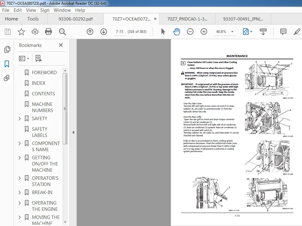
Image Preview:
Table of Contents:
Kawasaki Wheel Loader 70Z7 Service manual + Parts manual + Wiring diagrams + Troubleshooting manual
SECTION 1 GENERAL.....................................................................  8
Group 1 Precautions for Disassembling and Assembling.................................. 10
	Precautions for Disassembling and Assembling...................................... 10
Group 2 Tightening.................................................................... 16
	Tightening Bolts and Nuts......................................................... 16
	Piping Joint...................................................................... 19
Group 3 Painting...................................................................... 26
	Painting.......................................................................... 26
Group 4 Bleeding Air.................................................................. 34
	Bleeding Air from Hydraulic Oil Tank.............................................. 34
	Bleeding Air from Hydraulic System................................................ 35
	Bleeding Air from Fuel System..................................................... 37
	Bleeding Air from Radiator........................................................ 39
	Bleeding Air from Brake (Axle).................................................... 40
Group 5 Releasing Pressure............................................................ 42
	Front Attachment Hydraulic Circuit Pressure Release Procedure..................... 42
	Ride Control Accumulator Pressure Release Procedure............................... 43
Group 6 Preparation................................................................... 44
	Preparation before Inspection and Maintenance..................................... 44
SECTION 2 MAINTENANCE STANDARD........................................................ 48
Group 1 Body.......................................................................... 50
	Center Hinge...................................................................... 50
Group 2 Travel System................................................................. 52
	Axle.............................................................................. 52
Group 3 Front Attachment.............................................................. 56
	Pin and Bushing................................................................... 56
	Standard Dimensions for Lift Arm and Bucket....................................... 58
	Cylinder.......................................................................... 60
SECTION 3 BODY........................................................................ 62
Group 1 Cab........................................................................... 64
	Removal and Installation of Cab................................................... 64
Group 2 Counterweight................................................................. 86
	Removal and Installation of Counterweight......................................... 86
	Removal and Installation of Battery Box (Without Battery Disconnect Switch)....... 92
	Removal and Installation of Battery Box (Attached Battery Disconnect Switch)...... 96
	Removal and Installation of Battery Disconnect Switch............................. 98
Group 3 Center Hinge..................................................................102
	Removal and Installation of Center Hinge..........................................102
Group 4 Engine........................................................................122
	Removal and Installation of Engine................................................122
	Removal And Installation of Exterior Parts........................................152
	Removal and Installation of Air Cleaner...........................................166
Group 5 Radiator Assembly.............................................................170
	Replacement of Radiator, Oil Cooler, and Intercooler .............................170
Group 6 Hydraulic Oil Tank............................................................190
	Removal and Installation of Hydraulic Oil Tank....................................190
Group 7 Fuel Tank.....................................................................202
	Removal and Installation of Fuel Tank.............................................202
Group 8 Pump Device...................................................................208
	Removal and Installation of Pump Device...........................................208
	Disassembly of HST Pump...........................................................224
	Assembly of HST Pump..............................................................228
Group 9 Control Valve.................................................................248
	Removal and Installation of Control Valve.........................................248
	Disassembly of Control Valve......................................................256
	Assembly of Control Valve.........................................................261
Group 10 Pilot Valve..................................................................268
	Removal and Installation of Pilot Valve ..........................................268
	Removal and Installation of Pilot Valve (Two Lever Type )  .......................274
	Disassembly of Pilot Valve........................................................280
	Assembly of Pilot Valve...........................................................283
	Disassembly of Pilot Valve (Two Lever Type).......................................288
	Assembly of Pilot Valve (Two Lever Type)..........................................294
Group 11 Brake Charge Valve...........................................................302
	Removal and Installation of Brake Charge Valve....................................302
	Structure of Brake Charge Valve...................................................316
	Removal and Installation of Brake Accumulator.....................................318
Group 12 Manifold Valve...............................................................322
	Removal and Installation of Manifold Valve........................................322
	Disassembly of Manifold Valve.....................................................336
	Assembly of Manifold Valve........................................................338
Group 13 Solenoid Valve...............................................................342
	Removal and Installation of Exhaust Filter Regeneration Control Solenoid Valve....342
	Structure of Exhaust Filter Regeneration Control Solenoid Valve...................346
Group 14 Priority Valve...............................................................348
	Removal and Installation of Priority Valve (without Secondary Steering)...........348
	Removal and Installation of Priority Valve (with Secondary Steering)..............354
	Structure of Priority Valve.......................................................360
Group 15 Cooling Fan System...........................................................362
	Removal and Installation of Fan Valve.............................................362
	Structure of Fan Valve............................................................366
	Removal and Installation of Fan Motor.............................................368
	Structure of Fan Motor............................................................372
Group 16 Ride Control Device..........................................................374
	Removal and Installation of Ride Control Valve....................................374
	Disassembly of Ride Control Valve.................................................380
	Assembly of Ride Control Valve....................................................383
	Removal and Installation of Ride Control Accumulator..............................388
Group 17 Exhaust Filter...............................................................392
	Removal and Installation of Exhaust Filter........................................392
	Disassembly of Exhaust Filter.....................................................400
	Assembly of Exhaust Filter........................................................402
SECTION 4 TRAVEL SYSTEM...............................................................404
Group 1 Tire..........................................................................406
	Removal and Installation of Front Tire............................................406
	Removal and Installation of Rear Tire.............................................410
Group 2 HST Motor.....................................................................416
	Removal and Installation of HST Motor.............................................416
	Disassembly of HST Motors 1, 2....................................................426
	Assembly of HST Motors 1, 2.......................................................428
Group 3 Transmission..................................................................432
	Removal and Installation of Transmission..........................................432
	Disassembly of Transmission.......................................................444
	Assembly of Transmission..........................................................453
	Disassembly of Clutch Assembly....................................................464
	Assembly of Clutch Assembly.......................................................466
	Disassembly of Clutch Pressure ControlSolenoid Valve..............................468
	Assembly of Clutch Pressure ControlSolenoid Valve.................................470
Group 4 Axle..........................................................................472
	Removal and Installation of Front Axle............................................472
	Removal and Installation of Rear Axle.............................................476
	Disassembly of Axle...............................................................484
	Assembly of Axle..................................................................500
Group 5 Propeller Shaft...............................................................526
	Removal and Installation of Propeller Shaft.......................................526
Group 6 Brake Valve...................................................................534
	Removal and Installation of Brake Valve...........................................534
	Disassembly of Brake Valve........................................................544
	Assembly of Brake Valve...........................................................546
Group 7 Steering Device...............................................................550
	Removal and Installation of Steering Valve........................................550
	Disassembly of Steering Valve.....................................................556
	Assembly of Steering Valve........................................................559
	Removal and Installation of Steering Cylinder.....................................564
	Disassembly of Steering Cylinder..................................................572
	Assembly of Steering Cylinder.....................................................576
	Removal and Installation of Steering Accumulator..................................582
Group 8 Secondary Steering Device.....................................................584
	Removal and Installation of EmergencySteering Pump................................584
SECTION 5 FRONT ATTACHMENT............................................................592
Group 1 Front Attachment..............................................................594
	Removal and Installation of Front Attachment......................................594
	Removal and Installation of Bell Crank (Lever)....................................608
	Removal and Installation of Bucket................................................618
Group 2 Cylinder......................................................................624
	Removal and Installation of Lift Arm Cylinder.....................................624
	Removal and Installation of Bucket Cylinder.......................................632
	Disassembly of Lift Arm Cylinder..................................................646
	Assembly of Lift Arm Cylinder.....................................................650
	Disassembly of Bucket Cylinder....................................................654
	Assembly of Bucket Cylinder ......................................................658
INDEX.................................................................................662
Description:
Kawasaki Wheel Loader 70Z7 Service manual + Parts manual + Wiring diagrams + Troubleshooting manual
The service manual covers the following files:
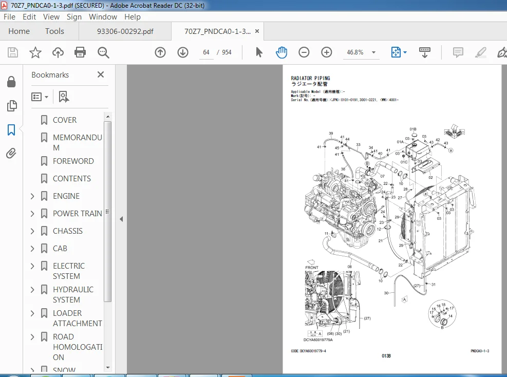
70Z7_PNDCA0-1-3.pdf
70Z7+OCEA(00723).pdf
70Z7B_TS_US(93208-00860) (1).pdf
70Z7B_TS_US(93208-00860).pdf
70Z7B+FS+US.pdf
93305-00310_50_60Z7.pdf
93306-00292.pdf
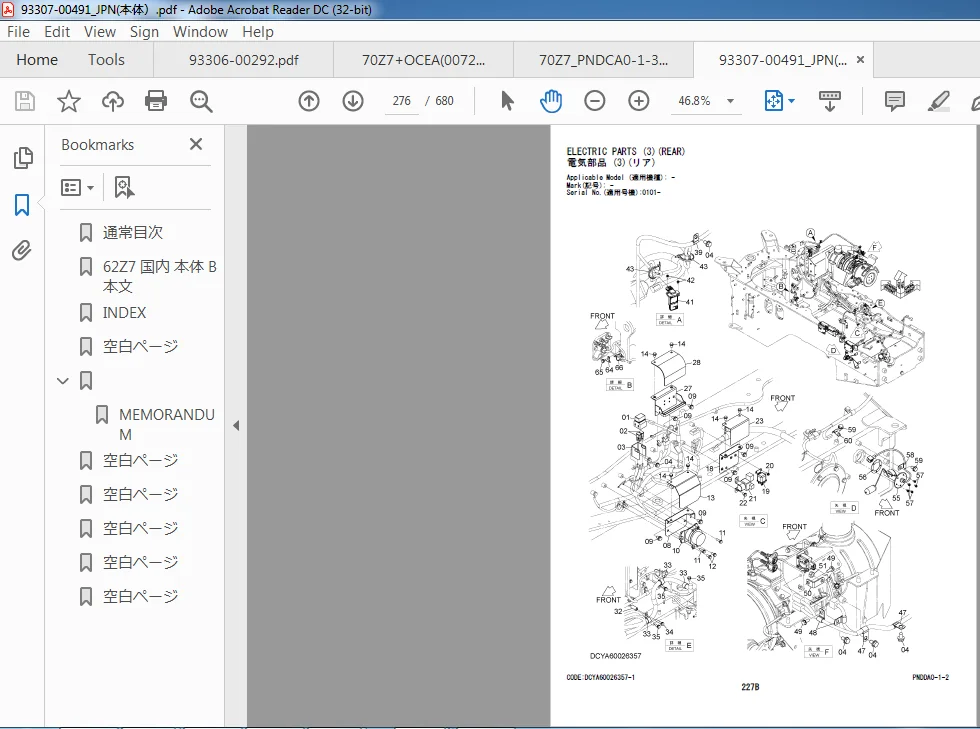
93307-00491_JPN(??).pdf
93307-00511_JPN_EU_USA_OCEAN(??).pdf
93308-00590.pdf
-E-70Z7B+DR+US-1.pdf
-E-70Z7B+DR+US-2.pdf
-E-70Z7B+F&S+Attachment_USA.pdf
PNDCA0-E1-3.pdf
??50+60Z7EG 93305-00310 (1).pdf
??50+60Z7EG 93305-00310.pdf
??60Z7(USA)93306-00310.pdf
??60Z7??(JPN+USA)+93306-00292.pdf
??70Z7B+?????.pdf
60Z7(US-F&S)-Cover (1).pdf
60z7+USA+??+93306-00310.pdf
62Z7+D&R(US,OCE)(93207-01071).pdf
70Z7,TM7+DR+US(93208-00772)-1.pdf
70Z7,TM7+DR+US(93208-00772)-2.pdf
70Z7_OMM(93108-00690)US.pdf
70Z7_OMM(93108-00690)US-Cover.pdf
- Our shop manuals consist of the Technical Manual, the Workshop Manual and the Engine Manual.
Information included in the Technical Manual: Technical information needed for machine pre-delivery and delivery, operation and activation of all devices and systems, operational performance tests, and troubleshooting procedures. Each page has a number, located on the center lower part of the page, and each number contains the following information: Example: Technical Manual: T 1-3-5 T Technical Manual 1 Section Number 3 Group Number 5 Consecutive Page Number for Each Group - Information included in the Workshop Manual: Technical information needed for maintenance and repair of the machine, tools and devices needed for maintenance and repair, maintenance standards, and removal / installation and assembly / disassembly procedures. Information included in the Engine Manual: Technical information needed for machine pre-delivery and delivery and maintenance and repair of the machine, operation and activation of all devices and systems, troubleshooting and assembly / disassembly procedures
Please Note:
- This is the SAME exact manual used by your dealers to fix your vehicle.
- The same can be yours in the next 2-3 mins as you will be directed to the download page immediately after paying for the manual.
- Any queries / doubts regarding your purchase, please feel free to contact [email protected]